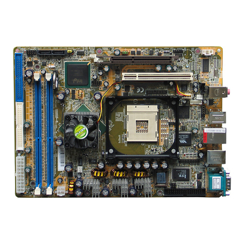
Shuttle HOT-641/P User manual

HOT-641/P
Pentium™IIprocessor
Based AGPMAINBOARD
User's Manual

FCC Notice:
This equipment has been tested and found to comply with the limits for a Class B digital device, pursuant to Part 15 of FCC
Rules. These limits are designed to provide reasonable protection against harmful interference in a residential installation.
This equipment generates, uses and can radiate radio frequency energy. If not installed and used properly, in strict accor-
dance with the manufacturer’s instructions, may cause harmful interference to radio communications. However, there is no
guarantee that interference will not occur in a particular installation. If this equipment does cause interference to radio or
television reception, which can be determined by turning the equipment off and on, the user is encouraged to try to correct
the interference by one or more of the following measures :
Reorient or relocate the receiving antenna.
Increase the separation between the equipment and receiver.
Connect the equipment into an outlet on a circuit different from that to which the receiver is connected.
Consult the dealer or an experienced radio/television technician for help and for additional suggestions.
The user may find the following booklet prepared by the Federal Communications Commission helpful “How to Identify
and Resolve Radio-TV Interference Problems.” This booklet is available from the U.S. Government Printing Office.
Washington, DC 20402, Stock 004-000-00345-4
FCCWarning
The user is cautioned that changes or modifications not expressly approved by the manufacturer could void the user’s
authority to operate this equipment.
Note : In order for an installation of this product to maintain compliance with the limits for a Class B device, shielded
cablesandpowercordmustbeused.
CE Notice:
Following standards were applied to this product, in order to achieve compliance with the electromagnetic
compatibility :
- Immunity in accordance with EN 50082-1: 1992
- Emissions in accordance with EN 55022: 1987 Class B.
NOTICE
Copyright 1997.
All Right Reserved
Manual Ver 1.0
All information, documentation, and specifications contained in this manual are subject to change without prior
notification by the manufacturer.
The author assumes no responsibility for any errors or omissions which may appear in this document nor does
it make a commitment to update the information contained herein.
TRADEMARKS
Intel is a registered trademark of Intel Corporation
PentiumII Processor is a registered trademark of Intel Corporation
PC/AT is a registered trademark of International Business Machine Corporation.
PS/2 is a registered trademark of IBM Corporation.
All other brand and product names referred to in this manual are trademarks or registered trademarks of their
respective holders.


2
TABLEOFCONTENTS
T
T
PREFACE ...................................................................................................................3
CHAPTER 1 INTRODUCTION ...........................................................................................4
Specification ....................................................................................................................................... 4
Accessories of HOT-641/P................................................................................................................. 6
CHAPTER 2HARDWARE CONFIGURATION........................................................................7
ThePentiumII &Celeron Processor ................................................................................................. 8
Whatdoesthe RM(RetentionMechanism) consistof ..................................................................... 8
InstalltheRetention MechanismandHeat SinkSupport ................................................................. 9
InstallPentium IIProcessor ............................................................................................................. 11
Celeron Processor S.E.P.P only RM Assembly Procedure .............................................................12
WhatdoesCeleron Processor RMconsist of .................................................................................. 13
InstallCeleronProcessor.................................................................................................................. 14
CPU External Clock (System Clock) setting................................................................................... 14
Jumpers.............................................................................................................................................. 15
CPUMultiplierand System FrequencySetting- JP11 ~JP14& J201..........................................15
ClearCMOS- JP6 ............................................................................................................................ 17
FlashEEPROMVpp - JP9 ............................................................................................................... 17
Connectors & Sockets ...................................................................................................................... 18
CHAPTER 3MEMORY CONFIGURATION .........................................................................21
CHAPTER 4 FLASH UTILITY ........................................................................................22
CHAPTER 5 AWARD BIOS SETUP ..............................................................................24
The Main Menu................................................................................................................................. 25
StandardCMOSSetup...................................................................................................................... 27
BIOS Features Setup......................................................................................................................... 29
ChipsetFeaturesSetup ..................................................................................................................... 32
PowerManagementSetup ................................................................................................................ 35
PCIConfigurationSetup .................................................................................................................. 38
IntegratedPeripherals ....................................................................................................................... 40
PasswordSetting............................................................................................................................... 43

3
PREFACE
P
P
HOT-641/Pisa highly integratedIBMPC/AT compatible systemboarddesigned to
meettheindustry's mostdemanding desktopapplications.
Basedonthe Intel82440BX AGPsetchipsetwhich supportup to500MHzPentiumTMII
processorwithMMXtechnology.
Onboardfour 168-pinDIMMsocket supportupto 1GBSDRAM.
HOT-641/Pisequipped withanAccelerated GraphicsPort(A.G.P.), a high-performance
interconnectfor graphic-intensiveapplication,such as3D applications.The A.G.P.is
independentofthe PCI busand is designedtoexclusively usewithgraphical-display
devices. The HOT-641/P supports 3.3 V A.G.P. devices with data transfer rates up to
133MHz,allowing datathroughputof 500MB/sec.
TheIntel's82440BX AGPsetchipsetprovides an integratedBus Mastering IDEcontrol-
lerwithtwo highperformance IDEinterfaces whichallowsup tofour IDEdevices
connectionandup to 33MB/sec of datatransferrates.
Theon-boardGigaI/Ocontroller providesstandard PCI/Ofunctions:
floppydriveinterface, two FIFOserialports, anInDAdevice port andaSPP/EPP/ECP
capable parallel port.
HOT-641/Pisbuilt withfourPCI localbus slots providinga high bandwidthdata path
fordata-movementintensive functions suchasgraphics, and withthreeISA slots.
HOT-641/Pprovidesthe foundationfor costeffective,high performanceand highly
expandableplatforms, whichdeliversthelatestintheIntelPentiumTM IIprocessorand
newadvanced chipsettechnology.

4
SPECFICATION
1
1
TheHOT-641/PMainboard iscarefullydesigned forthe demanding PCuser who wantshigh perfor-
manceandmany intelligentfeaturesin a compactpackage:
IntelChipset:
FeaturesIntel's440BX AGPset withI/O subsystems.
CPUSupport:
IntelPentiumII processor233/66 ~333/66MHz and350/100 ~500/100MHz.
Celeronprocessor 266~333 MHz.
VersatileMemorySupports:
Equipped with four DIMM sockets support168-pin 3.3VSDRAMmemory modules,total
memorysizeup to 1GB.
ConfigurablesupportforECC(Error Checkingand Correcting)
PCIandISAExpansionSlots:
Providesfour32-bit PCI slotsand three 16-bitISAslots.
AGPSlot:
SupportsAccelerated GraphicsPortcardsforhigh performance,componentlevelinterconnect
targeted at 3D graphical display applications.
OnboardGiGA-I/O:
Providesone Floppyport; oneoptional PS/2mouseconnector; twohigh-speedUARTcompatible
serial ports and one parallel port with ECP and EPP capabilities. Serial Port 2 can also be directed
fromCOM2to the InfraredModulefor wireless connections.
OnboardPCIBusMasterIDEController:
Two UltraDMA/33 BusMaster IDE Portssupports four IDEdevices up to33 MB/sec IDEtrans-
fersandsupports EnhancedPIOModes 3 and4 and BusMaster IDE DMAMode 2 devices.
Onboard20-pinATXPower Supply:
ProvidesATXpower connectoronboardsupports soft-on/offfunction.
SystemBIOS:
Provideslicensed AwardV4.51PG BIOSon FlashEEPROM.
SupportsGreenPC,DMIand Bundledwith NCRSCSIBIOS.
ACPI:
Support ACPI(Advanced Configurationand PowerInterface) function. ACPI provide more
EnergySavingFeaturesforthe futureoperating systemsupporting OSDirectPower Management
(OSPM)functionality.

5
BoardSize:
ATX form factor 305mm x 220mm.
AdvancedFeatures:
LowEMI--Spread Spectrum builtin- ±1.5% modulationand automatic clockshut-offof unused
PCI/SDRAMSslots toreducethe EMI.
"AdvancedConfigurationandPowerInterface" ReadyforPC'97.
DualFunctionPower Button --Thesystem can beone of twostates, one is Suspendmodeand
the other is the Soft-off mode. Pushing the power button for less than 4 seconds will place the
systemintoSuspend mode. Whenpushthe powerbutton for morethan 4seconds,the system
enterstheSoft-off mode.
Wake-ON-LAN --The systemwill power-onautomatically byactivatingofLAN.
(Thisfunctionsupport Intel LANcard only).
ModemRingPower-on -- Thesystemwill power-onautomaticallyby activatingof modemring.
MoreAdvancedFeatures(HOT-641/PP):
VoltagesMonitoring--System voltageslevelsaremonitoredto ensurestable currenttomain
boardcomponents.
Systemvoltagesinclude VCORE and VL2 for CPU, and +5V, +12V, -5V, -12V for system.
FANStatusMonitoring-- TopreventCPU overheat,CPU fans ismonitored forRPMand failure.
(CPUCoolingFANwithRPM sensoris required)

6
ACCESSORIES OF HOT-641/P
Figure 1-1

7
HARDWARECONFIGURATION
2
2
The Pentium™ II & Celeron™ Processor
ThePentiumII and Celeron processoristhe next memberof the P6processorfamily. It
combinesthe architecturaladvancesinthePentiumProprocessorwiththeinstructionset
extensionsofMMX technology. It isfully compatible withthehuge baseofIntel architec-
ture-basedPCsoftware. Additional, thePentiumII processordeliversnew levelsofperfor-
manceforadvancemediaand communicationssoftware includingpowerful,realistic
graphicsandimaging capabilities, videoconference, and theabilityto runfull-screen,full-
motionvideo. Thecombination ofthese advancedtechnologiesmakes thePentium II
processortheideal choicefoeexecuting modem32-bitcompute-intensive andmultimedia-
enhancedapplication workloadsusingadvanced32-bit operatingsystems.
ThePentiumII andCeleronprocessor bothhavea separate,32KB,on-chip, non-blocking L1
cachewhichrun at theprocessorfrequency, Pentium IIprocessor also hasa512KB or
256KB on-board L2 non-blocking cache runs at half the processor speed.
ThePentiumII processorusingSingle Edge Contact(S.E.C.) cartridge packagingtechnol-
ogywhichenables highvolume availability,improvedhandling protection.
TheCeleronprocessorusingSingle EdgeProcessor Package.(S.E.P.P.)
Figure2-1shows the front,rear and topviewsof PentiumIIprocessor (without heatsink
mounted).
Figure2-2shows theprimary and non-primaryside ofCeleronprocessor withoutheatsink
mounted and with heat sink mounted.
Figure 2-2
Figure 2-1

8
What does the RM (Retention Mechanism) consist of
PentiumIIprocessor requiresthe RetentionMechanism (RM)andoptional HeatSink
Support(HSS)to holdthebase processorinthe S.E.C.cartridge.
Followinginstallationprocedurewilldisplay howto installthesemechanism.
RetentionMechanismpackage consists of2 separate partsandoptional HeatSinkSupport
consistsof3 separateparts.
Normally,dependon the typeofheat sink,HeatSink Support isnot always available. For
someheatsink attached onpentium II processormightnot fittoinstall Heat SinkSupport
which introduced on this manual. So, the procedure of Heat Sink Support installation just
yourreferenceonly.
RetentionMechanism(RM) -
PlasticGuidewithcaptivenuts thathold the
S.E.C. Cartridge in the Slot1 connector.
(RefertoFigure2-1-1)
RMAttachPin (RMAP) -
Plasticpinsinsertedthroughthe RMto secure
ittothemainboard(four requiredper Assembly).
(RefertoFigure2-1-2)
Heat Sink Support Base (HSSBASE) -
Plasticsupport barmountedtothemainboard
undertheATX heat sink.
(RefertoFigure2-1-3)
HSSPin(HSSPIN) -
Plasticpinsinserted through theHSSBASEto secure
ittothe mainboard(tworequired perAssembly).
(RefertoFigure2-1-4)
HSSTopBar (HSSTOP) -
Plasticbar thatclipsontotheHSSBASE
throughthefins on theATXheat sink.
(RefertoFigure2-1-5)
Figure 2-1-3
Figure 2-1-4
Figure 2-1-5
Figure 2-1-1
Figure 2-1-2

9
Install the Retention Mechanism and Heat Sink Support
Placethemainboard onaworkbench (not ina chassis). Besure that themainboard is bare
(thatis,no SIMMs,cables,or cards areinstalled).
InstalltheRetentionMechanism:
1.Findsout the RetentionMechanism (RM)
MountingHolesand "Pin 1"markof Slot 1
onHOT-641/P mainboard.
(RefertoFigure 2-8)
2.Insertthe RetentionMechanism(RM)
around theSlot 1. Besure the SquareCut
Mark ofRMhave thesame orientationof
Slot1pin 1.(Refer toFigure 2-9)
3.Insertfour RMAttachPin through theRM
tosecureittothe mainboard(four required
per Assembly). (Refer to Figure 2-9)
Figure 2-8
Figure 2-9

10
InstalltheHeatSinkSupport:
Beforeyouinstall the HeatSinkSupport, please checkyourPentium II processor,if you have
anIntelboxed processor (Referto Figure2-10),you can ignorethis section. InIntelboxed
processorkit,it will includesit'sown Heat SinkSupport accessories andinstallmanual, you
canInstallthe Heat SinkSupportonto the mainboardby following theIntelprocessor kit's
instructions.
Figure2-11shows theOEMtype PentiumIIprocessor withactiveheat sink.
1.Findsout theHeatSink Support(HSS)
MountingHoleson HOT-641/Pmain
board.Noticethat one holeislarger than
theotherhole. (Refer toFigure 2-8)
2.Thereare two plasticpegson the
bottom of Heat Sink Support Base
(HSSBASE) bar. Mount the two black
plastic pegs onto the mainboard. Notice
that one hole and the bar of one peg are
largerthanthe other holeandpeg. (Refer
to Figure 2-12)
3.Insertthe Heat SinkPins (HSSPIN)
throughtheHSSBASE to secureitto the
mainboard.(Referto Figure2-12)
4.Insertthe Pentium IIintothe RM
firmly(Pleaserefer to"Install PentiumII
processor" section), Slide the Heat Sink
TopBar (HSSTOP)onthe supports
forwardtoclip ontotheHSSBASE
throughthefins ofHeatSink. (Referto
Figure 2-13)
Figure2-10 Figure2-11
Figure2-12
Figure2-13

11
Install Pentium™ II Processor
Figure2-14
Pushthelatchesonthe processortoward thecenterof theprocessor untilthey clickintoplace.
Holdtheprocessor so thatthefan shroud isfacing toward theHeatSink Support Basebaron
themainboard. Slidethe processorintothe RetentionMechanism.Ensure thatthealignment
notchinthe processor fitsover the plugin Slot 1.Pushthe processordownfirmly, witheven
pressureonboth sides ofthetop, until itis seated.
Pushthelatches on theprocessor outward untiltheyclick intoplacein the RetentionMecha-
nism.Thelatches must besecuredfor proper electricalconnectionof the processor. Slidethe
HeatSinkTop Bar(HSSTOP) on thesupports forwardtoclip ontothe HSSBASE throughthe
finsofHeat Sink.(Alsorefer to "InstallHeat Sink Support"section)
Attach the end of the power cable to the three-pin connector on the mainboard or to the power
cordofATX power supply(depend on powercabletype ofFan/HeatSink).

12
Celeron™Processor S.E.P.P.Only Retention MechanismAssembly
Procedures
Theseprocedureshave beenincludedto helpassemblethe S.E.P.P.(Single
EdgeProcessor Package)only RetentionMechanism.
Pleasefollowthem exactly:
RequiredComponents
SEPP(Figure2-15)
Heatsink(Figure2-16)
HeatsinkRetentionClip (Figure2-17)
Primary Side
Figure 2-16
Figure 2-15
Figure 2-17
Procedures
Assembleallparts on astaticfree bench using
properoperatorgrounding and anESD mat.
Carefullyinsertall four heatsinkcliplegs into
SEPP.(Figure2-18)
Clip basemust belocated onthe non-primary
side.(Figure 2-19) FYI- The sideofthe clip
platewhichtouches thesubstrate iscovered
withamylarinsulator. Thisinsulator prevents
theclip fromshortinglinesonthe substrate.
Beforeyoufully engage twolegs of theclipinto
theheatsink (Figure2-20),makesureyou
remove the blue film covering the thermal
interface. Thebluefilm protects thethermal
interfacefrom damageduring shipping.
Grasptheheatsink clipassembly betweenthe
clip base and the heatsink. Do not bend or
applypressuredirectly toSEPP.
Usinganonmetallic stockorscrew driver,push
theremainingtwocliplegs intothe heatsink.
Caution: Takecarenot tocontact passivelyor
scratchSEPPwhen using screwdriveror bar
stock.
Verify that all the feet on the clip are fully
engagedand seatedonthe heatsink.
(Figure 2-21)
Non-primarySide
Figure 2-18
Non-primarySide
Figure 2-19
Primary Side
Figure 2-20
Figure 2-21

13
What does the Celeron™ Processor RM consist of
Figure 2-22
Figure 2-23
Install the Celeron™ Processor RM
Celeron™ Processor requires theRetention Mechanism (RM)to holdthebase processorinthe
S.E.P.P.
Followinginstallationprocedure willdisplay howto installthesemechanism. Please consultto
yoursupplierfor the mechanism.
RetentionMechanism packageconsistsof2sets separateparts.
Eachsetconsists ofoneRM, two Postsand two lockpins.
RetentionMechanism(RM) -
TwoPlastic Guidesthat holdthe
S.E.P.P in the Slot 1 connector.
(Referto Figure2-22)
Post Pins -
FourPostpins are pushintothe RM's holes
to fix RM on the PCB.
Lock Pins -
FourLockpins are pushintothe Post holes
to lock up RM on the PCB.
Placethemainboard onaworkbench (not ina chassis). Besure that themainboard is bare
(thatis,no SIMMs,cables,or cards areinstalled).
1. Findsoutthe RetentionMechanism (RM)Mount-
ingHolesof Slot 1onHOT-641/P main board.
(Referto Figure2-23)
2. Inserttwo RetentionMechanism (RM)face toface
onoppositeside oftheSlot 1.(Referto Figure 2-23)
3. InsertfourPost Pin throughtheRM to fixitto the
mainboard. (Referto Figure2-23)
4. Insert four Lock Pin through the Post Pin to lock
RMtothe mainboard.(Referto Figure2-23)

14
Install Celeron™ Processor
Figure 2-25Figure 2-24
Holdtheprocessor sothatthe Heatsinkisfacing towardtheDIMM socketsonthe mainboard.
Slidetheprocessor intothe RetentionMechanism. Pushtheprocessor downfirmly, witheven
pressureonboth sides ofthetop, until itis seated. (RefertoFigure 2-24 andFigure2-25)

15
Figure2-26
Jumpers
HOT-641/Pmainboardprovides JumpersJP11,JP12, JP13andJP14 tofigurethe CPU core
clockmultiplier. Byinserting mini jumpersonthese jumpers, theusercan figure theHostBus
Clock/CPUCoreClock ratio(multiplier)from 2.5X to5X.
Figure2-26shows the positionofJP11, JP12, JP13,JP14 and J201onthe mainboard.
Severalhardwaresettings are madethrough the useofjumper capstoconnect jumper pinson
the main board. The jumper's pin 1 on main board will be on the top or on the left when hold-
ingthe mainboardwith thekeyboard connectoraway fromyourself.
Jumpers with two pins will be shown as for Close (On) and for Open (Off).
To connect the pins, simply place a plastic jumper cap over the two pins.
Jumpers with three pins will be shown as for Pin 1-2 Close (On) and for Pin 2-3
Close(On).To connect thepins, simply placeaplastic jumpercapover the twopins.
CPU External Clock (System Clock) Setting
HOT-641/PsupportSystem Clock(CPU ExternalClock) adjustfrom66MHz to112MHz.
SystemClock66, 68, 75,83MHz (for 66MHzbased Pentium II/CeleronProcessor)and 100,
103,112MHz (for100MHz basedPentium IIprocessor)configure onBIOS "Chipset Features
Setup".
Note: 1.For66MHzbased Pentium II/Celeron processors,68,75and 83
MHzareforover-clockusage,it is not a recommended general practice.
2.For100MHzbasedPentiumIIprocessors,103, 112 MHz is for over-clock
usage, it is not a recommended general practice.
CPU Multiplier and System Frequency Setting - JP11 ~ JP14 and J201

16
CPUConfigurationTable (Table 2-1)showsthe PentiumII233/66MHz ~ 333/66MHzand350/
100MHz~ 500/100MHz,and Celeronprocessor 233MHz~ 333MHzquick setting.
Table2-2shows hardwaresetupfor systemfrequency. WhenJ201 isopen,the systemfrequency
willbeset to66MHz basedclock (66~83MHzselectable)or 100MHzbased clock(100~112MHz
selectable) depend on processor type. When J201isclosed,only 66MHzbasedclockavailable.
MultiplierTable (Table2-2-1) showsall ofthemultipliersthatthemainboardcansupport.
MultiplierJP11/JP12/
JP13/JP14
2.5x
3x
3.5x
4x
4.5x
5x
Multiplier Table
SystemFrequency J201
Force systemfrequency
downto66*MHzbased
Systemauto-detect66*or
100** MHzbased
processor(default)
Table 2-2
Table 2-2-1
* System provides 66, 68, 75 and 83 MHz for 66MHz
based Pentium II/Celeron Processor.
** System provides 100, 103, 112 MHz for 100MHz based
Pentium II processor.
Hardware Setup for System Frequency
PentiumII
/Celeron
Processor
System
Clock MultiplierPentiumII
ProcessorSystem
Clock Multiplier
233MHz66 MHz3.5x350MHz100 MHz3.5x
266MHz66 MHz4x400 MHz100 MHz4x
300MHz66 MHz4.5x450MHz100 MHz4.5x
333MHz66 MHz5x500 MHz100 MHz5x
CPU Configuration Table
Table 2-1

17
Clear CMOS - JP6
HOT-641/P mainboardsupports jumper JP6for dischargingmainboard'sCMOSmemory.
This jumper can clear the CMOS data stored in the Giga I/O chip. To clear the CMOS data
pleasefollowlisted steps:
1) Turn off the PC,
2)Removemini jumper fromJP6pin 1-2,
3)Insertmini jumper toJP6pin 2-3 forabrief while,
4)Removemini jumper fromJP6in 2-3,
5)Reinsertmini jumper toJP6pin 1-2,
6) Turn on the PC.
Flash EEPROM Vpp - JP9
HOT-641/Pmainboardsupports
twotypesof FlashEEPROM:5
volt and 12 volt. By setting up
jumper JP9, the main board can
useboth5V or12Vflash
EEPROMwith newsystem BIOS
filesasthey come available.
JP9 Pin 2-3 Close
for 5V Flash EEPROM
JP9 Pin 1-2 Close
for 12V Flash EEPROM
Figure2-27
Factory Reserved Jumpers
Factory Reserved
JP10 1 - 2 Close
JP9 2 - 3 Close
J40 2 - 3 Close

18
Connectors
Front Panel Connectors
Hardware Reset Connector
- J29
Attach2-pin hardwareresetswitchtoit.
Closingthe resetswitchrestarts the
system.
Power LED Connector - J25
PowerLED(CHS LED)connector isa
3-pinconnectorfor attached tothe case's
Power LED. Pin 1 and 3 are for power
LED and pin 2 is empty.
Speaker Connector - J27
PCspeakerconnector may attacha4-pin PC speakercablefrom the casetothis connector.
HDD LED Connector - J28
Attacha4-pin IDE driveLED cable tothisconnector. The LED lightswhen an IDEdeviceis active.
ATX Power On/Off Switch Connector - JP15(PWR_ON)
Attacha2-pin momentarytype switch tothis connectorforturning onor off yourATX powersupply.
Figure2-28

19
Back Panel Connectors
COM1/COM2Connectors
AttachCOM1/COM2device cablesto theseconnectors.
PS/2 Keyboard & PS/2 Mouse Connector
Two6-pinfemale PS/2 keyboard&Mouse Connectorsislocated at therear of themainboard.
PS/2Mouseon top ofconnectorand PS/2 Keyboardon the bottomofconnector. Plug the PS/2
keyboardandmouse jack intothis connector.
Parallel Port Connector
A 25-pin female connector is located at the rear of the main board. Plug the parallel port device
cableinto thisconnector.
USB1/USB2PortConnectors
Twofemaleconnectors are locatedatthe rear oftheboard. Plug
theUSBdevices jack intothis connector.
OtherConnectors
ATX Power Supply Connector - J30
Itisa twenty-pin maleheaderconnector. Plug the connectorfrom
thepowerdirectly ontothe boardconnectorwhile makingsure the
pin1is in itsposition. Themain boardrequiresa power supply
withatleast 200watts andpowergood signal.
IR Connector - JP22
Infrareddeviceconnectormayattach a5-pin infrared
device cable to this connector for enabling the infrared
transferfunction. Thismainboard meetsthespecification
of ASKIR and HPSIR. Figure 2-31shows JP22's
pinassignmentand Figure 2-33showJP22 location.
Figure2-30
Figure2-31
Figure2-29
Table of contents
Other Shuttle Motherboard manuals

Shuttle
Shuttle AK32A User manual

Shuttle
Shuttle AV64 User manual

Shuttle
Shuttle HOT-433 User manual

Shuttle
Shuttle MK35V User manual

Shuttle
Shuttle FS51 User manual

Shuttle
Shuttle MV43V User manual

Shuttle
Shuttle Spacewalker FE22 User manual

Shuttle
Shuttle AV49V User manual

Shuttle
Shuttle FB77 User manual

Shuttle
Shuttle AV42 User manual

Shuttle
Shuttle MB48 User manual

Shuttle
Shuttle SH610R4 Series User manual

Shuttle
Shuttle MT63 User manual

Shuttle
Shuttle MS11 User manual

Shuttle
Shuttle FN25 User manual

Shuttle
Shuttle Spacewalker MV17 User manual

Shuttle
Shuttle AB60/R User manual

Shuttle
Shuttle FT61 User manual

Shuttle
Shuttle FX83 User manual

Shuttle
Shuttle HOT-673 User manual