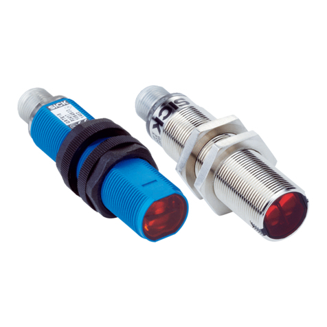
SICK GSE2 Flat Side User manual

Described product
G2F
GSE2F(S)
Manufacturer
SICK AG
Erwin-Sick-Str. 1
79183 Waldkirch
Germany
Production location
SICK Product Center Asia Pte. Ltd.
Singapore
www.sick.com.sg
Legal information
This work is protected by copyright. Any rights derived from the copyright shall be
reserved for SICK AG. Reproduction of this document or parts of this document is
only permissible within the limits of the legal determination of Copyright Law. Any modi‐
fication, abridgment or translation of this document is prohibited without the express
written permission of SICK AG.
The trademarks stated in this document are the property of their respective owner.
© SICK AG. All rights reserved.
Original document
This document is an original document of SICK AG.
2006/42/EC
NO
SAFETY
OPERATING INSTRUCTION
8023329.1HTH/2023-03-02 | SICK O P E R A T I N G I N S T R U C T I O N | GSE2 Flat Side 3
Subject to change without notice
en

Contents
1 About this document............................................................... 5
2 Safety information................................................................... 6
3 Product description................................................................. 6
4 Mounting.................................................................................. 7
5 Electrical installation............................................................... 7
6 Commissioning........................................................................ 9
7 Troubleshooting....................................................................... 12
8 Disassembly and disposal...................................................... 12
9 Maintenance............................................................................ 13
10 Technical specifications.......................................................... 14
11 Annex........................................................................................ 15
OPERATING INSTRUCTION
4O P E R A T I N G I N S T R U C T I O N | GSE2 Flat Side 8023329.1HTH/2023-03-02 | SICK
Subject to change without notice
en

1 About this document
1.1 Information on the operating instructions
Read these operating instructions carefully to familiarize yourself with the product and
its functions before commencing any work.
The operating instructions are an integral part of the product and should remain acces‐
sible to the personnel at all times. If the product is passed on to a third party, these
operating instructions should be handed over with it.
These operating instructions do not provide information on the handling and safe
operation of the machine or system in which the product is integrated. Information on
this can be found in the operating instructions for the machine or system.
1.2 Further information
You can find the product page with further information under the
pid.sick.com/{P/N}/{S/N}.
{P/N} corresponds to the part number of the product, see type label or packaging.
{S/N} corresponds to the serial number of the product, see type label or packaging
(optional, if specified).
The following information is available depending on the product:
•Data sheets
•These publication in all available languages
•CAD files and dimensional drawings
•Certificates (e.g., declaration of conformity)
•Other publications
•Software
•Accessories
1.3 Symbols and document conventions
Warnings and other notes
DANGER
Indicates a situation presenting imminent danger, which will lead to death or serious
injuries if not prevented.
WARNING
Indicates a situation presenting possible danger, which may lead to death or serious
injuries if not prevented.
CAUTION
Indicates a situation presenting possible danger, which may lead to moderate or minor
injuries if not prevented.
NOTICE
Indicates a situation presenting possible danger, which may lead to property damage if
not prevented.
OPERATING INSTRUCTION
8023329.1HTH/2023-03-02 | SICK O P E R A T I N G I N S T R U C T I O N | GSE2 Flat Side 5
Subject to change without notice
en
NOTE
Highlights useful tips and recommendations as well as information for efficient and
trouble-free operation.
Instructions to action
bThe arrow denotes instructions to action.
1. The sequence of instructions is numbered.
2. Follow the order in which the numbered instructions are given.
✓The tick denotes the results of an action.
2 Safety information
Connection, mounting and configuration of the product must only be car‐
ried out by qualified personnel.
2006/42/EC
NO
SAFETY
This product does not constitute a safety component as defined in the
Machinery Directive.
Do not install the product in places exposed to direct UV radiation (sun‐
light) or other weather conditions.
The product must be adequately protected against moisture and contami‐
nation.
2.1 Intended use
The GSE2F(S) is an opto-electronic through-beam photoelectric sensor (referred to as
“sensor” in the following) for the optical, non-contact detection of objects, animals, and
persons. A sender (GS) and a receiver (GE) are required for operation. If the product is
used for any other purpose or modified in any way, any warranty claim against SICK AG
shall become void.
3 Product description
3.1 Operating and status indicators
1 2
21
1Green LED: supply voltage active
2Receiver: Yellow LED: status of received light beam
OPERATING INSTRUCTION
6O P E R A T I N G I N S T R U C T I O N | GSE2 Flat Side 8023329.1HTH/2023-03-02 | SICK
Subject to change without notice
en

4 Mounting
Mount sensors (sender and receiver) using suitable mounting brackets (see the SICK
range of accessories). Align the sender and receiver with each other.
The minimum distance between sender and receiver is:
•GSE2F(S)-xxx1xx: 24 mm
•GSE2F(S)-xxx2xx: 72 mm
•GSE2F(S)-xxx5xx: 238 mm
NOTE
Swap the sender and receiver arrangement at every secondthrough-beam photoelec‐
tric sensor and ensure that there is sufficient distance between the through-beam
photoelectric sensors.
Receiver (GE)
Receiver (GE)
Sender (GS)
Sender (GS)
Sender (GS)
Receiver (GE)
Figure 1: Arrangement of several through-beam photoelectric sensors
Note the sensor's maximum permissible tightening torque of 0.1 Nm.
5 Electrical installation
The sensors must be connected in a voltage-free state (UV = 0V). The following informa‐
tion must be observed, depending on the connection type:
– Plug connection: note pin assignment: when the lid is open, the male connector
can be swiveled horizontally and vertically.
– Cable: wire color
Only apply voltage/switch on the voltage supply (UV >0V) once all electrical connec‐
tions have been established.
Explanation of the connection diagram (Tables pin assignment):
Q = switching outputs
n. c. = not connected
DC: 10 ... 30V DC
OPERATING INSTRUCTION
8023329.1HTH/2023-03-02 | SICK O P E R A T I N G I N S T R U C T I O N | GSE2 Flat Side 7
Subject to change without notice
en

Table 1: Pin assignment
GE2F(S)
-X14xx
-X54xx
1BN + (L+) + (L+)
2- - -
3BU - (M) - (M)
4BK Q Q
0.127 mm2, AWG281
4
3
2
1
1Before sensor date code 5220:
Cable BK: 0.1 mm2, AWG30
Table 2: Pin assignment
GS2F(S)
-X14xx
-X54xx
1BN + (L+) + (L+)
2- - -
3BU - (M) - (M)
4BK n. c. n. c.
0.127 mm2, AWG281
4
3
2
1
1Before sensor date code 5220:
Cable BK: 0.1 mm2, AWG30
OPERATING INSTRUCTION
8O P E R A T I N G I N S T R U C T I O N | GSE2 Flat Side 8023329.1HTH/2023-03-02 | SICK
Subject to change without notice
en

Table 3: Switching output
PNP Q
(≤ 50mA)
+ (L+)
Q
– (M)
+ (L+)
Q
– (M)
Q
(≤ 50mA)
+ (L+)
Q
– (M)
+ (L+)
Q
– (M)
NPN Q
(≤ 50mA)
+ (L+)
Q
– (M)
+ (L+)
Q
– (M)
Q
(≤ 50mA)
+ (L+)
Q
– (M)
+ (L+)
Q
– (M)
5.1 Notes on UL approval
The device shall be supplied from an isolating transformer having a secondary overcur‐
rent protective device that complies with UL 248 to be installed in the field rated either:
a) max 5 amps for voltages 0 ~ 20 V (0 ~ 28.3 V peak), or
b) 100 / Vp for voltages of 20 ~ 30 V (28.3 ~ 42.4 V peak).
Alternatively, they can be supplied from a Class 2 power supply.
UL Environmental Rating: Enclosure type 1
6 Commissioning
6.1 Alignment
Alignment
OPERATING INSTRUCTION
8023329.1HTH/2023-03-02 | SICK O P E R A T I N G I N S T R U C T I O N | GSE2 Flat Side 9
Subject to change without notice
en

Figure 2: Alignment GSE2F
6.2 Check the application conditions:
Sensing range
Observe the application conditions: Adjust the distance between the sender and the
receiver according to the corresponding diagram [see figure 3] (x = sensing range, y =
operating reserve).
If several through-beam photoelectric sensors which are installed next to one another
are to be used, we recommend swapping the sender/receiver arrangement at every
second through-beam photoelectric sensor and ensuring that there is sufficient dis‐
tance between the through-beam photoelectric sensors. By doing this, mutual interfer‐
ence can be prevented [see figure 1].
0
Distance in mm (inch)
20
(0.79)
40
(1.57)
60
(2.36)
80
(3.15)
100
10
1
Operating reserve
Figure 3: Operating reserve 50 mm
0
Sensing range
60
1
Sensing range max.
Distance in mm (inch)
20
(0.79)
40
(1.57)
80
(3.15)
60
(2.36)
0 40
Figure 4: Sensing range 50mm
OPERATING INSTRUCTION
10 O P E R A T I N G I N S T R U C T I O N | GSE2 Flat Side 8023329.1HTH/2023-03-02 | SICK
Subject to change without notice
en

40
(1.57)
0 80
(3.15)
120
(4.72)
160
(6.3)
200
(7.87)
100
1
Operating reserve
Distance in mm (inch)
10
Figure 5: Operating reserve 150 mm
0
Sensing range
0 150 200
1
Sensing range max.
Distance in mm (inch)
40
(1.57)
80
(3.15)
200
(7.87)
160
(6.3)
120
(4.72)
Figure 6: Sensing range 150mm
0
Distance in mm (inch)
200
(7.87)
400
(15.75)
600
(23.62)
800
(31.5)
100
10
1
Operating reserve
Figure 7: Operating reserve 500 mm
0
Sensing range
0 500 700
1
Sensing range max.
Distance in mm (inch)
200
(7.87)
800
(31.5)
600
(23.62)
400
(15.75)
Figure 8: Sensing range 500mm
1
Figure 9: Sensing range area
Use see table 3, page 9 to check the function. If the switching output fails to behave
in accordance with the table, check the application conditions. See section Fault diag‐
nosis.
6.3 Setting
Sensitivity setting
Sensor which it is not possible to set: The sensor is adjusted and ready for operation.
OPERATING INSTRUCTION
8023329.1HTH/2023-03-02 | SICK O P E R A T I N G I N S T R U C T I O N | GSE2 Flat Side 11
Subject to change without notice
en

Table 4: Sensing range setting
7 Troubleshooting
The Troubleshooting table indicates measures to be taken if the sensor stops working.
Table 5: Troubleshooting
LED/fault pattern Cause Measures
Yellow LED does not light up
even though the light beam
is aligned to the receiver and
there is no object in the path of
the beam
No voltage or voltage below
the limit values
Check the power supply,
check all electrical connec‐
tions (cables and plug connec‐
tions)
Voltage interruptions Ensure there is a stable power
supply without interruptions
Sensor is faulty If the power supply is OK,
replace the sensor
Yellow LED lights up, no object
in the path of the beam
The beam of light of apho‐
toelectric through-beam sen‐
sor hits the receiver of
another (neighboring)photo‐
electric through-beam sensor
Swap the sender and receiver
arrangement at every sec‐
ondthrough-beam photoelec‐
tric sensor and ensure that
there is sufficient distance
between the through-beam
photoelectric sensors, see
figure 1, page 7
8 Disassembly and disposal
The sensor must be disposed of in line with applicable country-specific regulations.
When disposing of them, you should try to recycle them (especially the precious met‐
als).
NOTE
Disposal of batteries, electric and electronic devices
•According to international directives, batteries, accumulators and electrical or
electronic devices must not be disposed of in general waste.
•The owner is obliged by law to return this devices at the end of their life to the
respective public collection points.
•
WEEE: This symbol on the product, its package or in this document,
indicates that a product is subject to these regulations.
OPERATING INSTRUCTION
12 O P E R A T I N G I N S T R U C T I O N | GSE2 Flat Side 8023329.1HTH/2023-03-02 | SICK
Subject to change without notice
en

9 Maintenance
This SICK sensor is maintenance-free.
We do, however, recommend that the following activities are undertaken regularly:
•Clean the optical interfaces and housing
•Check the fittings and plug connectors
Cleaning
NOTICE
Equipment damage due to improper cleaning.
Improper cleaning may result in equipment damage.
■Only use recommended cleaning agents and tools.
■Never use sharp objects for cleaning.
bClean the optical surfaces at regular intervals and, in the event of contamina‐
tion, with a lint-free lens cloth (part number 4003353) and plastic cleaner (part
number 5600006). The cleaning interval essentially depends on the ambient
conditions.
No modifications may be made to devices.
Subject to change without notice. Specified product properties and technical data are
not written guarantees.
OPERATING INSTRUCTION
8023329.1HTH/2023-03-02 | SICK O P E R A T I N G I N S T R U C T I O N | GSE2 Flat Side 13
Subject to change without notice
en

10 Technical specifications
GSE2F(S)-Xxx11 GSE2F(S)-Xxx21 GSE2F(S)-Xxx51
Sensing range 0 ... 40 mm 0 ... 150 mm 0 ... 500 mm
Sensing range max. 0 ... 60 mm 0 ... 200 mm 0 ... 700 mm
Light spot size / distance see chapter"Light
spot diameter"
see chapter"Light
spot diameter"
see chapter"Light
spot diameter"
Supply voltage UBDC 10 ... 30 V1) DC 10 ... 30 V1) DC 10 ... 30 V1)
Output current Imax. ≤ 50 mA ≤ 50 mA ≤ 50 mA
Switching frequency 800 Hz2) 800 Hz2) 800 Hz2)
Response time ≤ 0.625 ms3) ≤ 0.625 ms3) ≤ 0.625 ms3)
Enclosure rating IP67 IP67 IP67
Protection class III III III
Circuit protection A, C, D4) A, C, D4) A, C, D4)
Ambient temperature, operation -20 °C ... +50 °C -20 °C ... +50 °C -20 °C ... +50 °C
1) Limit value; residual ripple max. 5 Vss
2) Object with 90% remission factor (complies with standard white according to DIN5033)
2) With light / dark ratio 1:1
3) Signal transit time with resistive load
4) A = UB-connections reverse polarity protected
C = Interference suppression
D = outputs overcurrent and short-circuit protected
10.1 Dimensional drawing
3.5 (0.14)
Ø 2.3
(0.09)
4
(0.16)
5.5 (0.22) 2.2
(0.09)
10 (0.39)
11 (0.43)
27 (1.06)
1(0.04)
2.2
(0.09)
1
2
Figure 10: GSE2F
1Optical axis, receiver
2Optical axis, sender
4.5
(0.18)
Ø 2.3
(0.09)
2.2
(0.09)
2.2
(0.09)
11 (0.43)
4
(0.16)
11 (0.43)
21 (0.83)
1(0.04)
1
2
Figure 11: GSE2FS
1Optical axis, receiver
2Optical axis, sender
OPERATING INSTRUCTION
14 O P E R A T I N G I N S T R U C T I O N | GSE2 Flat Side 8023329.1HTH/2023-03-02 | SICK
Subject to change without notice
en

10.2 Light spot diameter
Ø 5
(0.2)
Ø 2
(0.08)
Ø 3
(0.12)
Sensor
0 50
(1.97)
5
(0.2)
30
(1.18)
Distance in mm (inch)
Diameter in mm (inch)
Figure 12: GSE2F(S), 50 mm version
Ø 20
(0.79)
Ø 2
(0.08)
Ø 7
(0.28)
Sensor
0 150
(5.91)
10
(0.39)
70
(2.76)
Distance in mm (inch)
Diameter in mm (inch)
Figure 13: GSE2F(S), 150 mm version
Ø 70
(2.76)
Ø 2
(0.08)
Ø 12
(0.47)
Sensor
0 600
(23.62)
10
(0.39)
100
(3.94)
Distance in mm (inch)
Diameter in mm (inch)
Figure 14: GSE2F(S), 600 mm version
11 Annex
11.1 Conformities and certificates
You can obtain declarations of conformity, certificates, and the current operating
instructions for the product at www.sick.com. To do so, enter the product part number
in the search field (part number: see the entry in the “P/N” or “Ident. no.” field on the
type label).
OPERATING INSTRUCTION
8023329.1HTH/2023-03-02 | SICK O P E R A T I N G I N S T R U C T I O N | GSE2 Flat Side 15
Subject to change without notice
en
Producto descrito
G2F
GSE2F(S)
Fabricante
SICK AG
Erwin-Sick-Str. 1
79183 Waldkirch
Alemania
Centro de producción
SICK Product Center Asia Pte. Ltd.
Singapore
www.sick.com.sg
Información legal
Este documento está protegido por la legislación sobre la propiedad intelectual. Los
derechos derivados de ello son propiedad de SICK AG. Únicamente se permite la
reproducción total o parcial de este documento dentro de los límites establecidos por
las disposiciones legales sobre propiedad intelectual. Está prohibida la modificación,
abreviación o traducción del documento sin la autorización expresa y por escrito de
SICK AG.
Las marcas mencionadas en este documento pertenecen a sus respectivos propieta‐
rios.
© SICK AG. Reservados todos los derechos.
Documento original
Este es un documento original de SICK AG.
2006/42/EC
NO
SAFETY
INSTRUCCIONES DE USO
8023329.1HTH/2023-03-02 | SICK I N S T R U C C I O N E S D E U S O | GSE2 Flat Side 17
Sujeto a cambio sin previo aviso
es

Índice
1 Acerca de este documento..................................................... 19
2 Para su seguridad.................................................................... 20
3 Descripción del producto........................................................ 20
4 Montaje.................................................................................... 20
5 Instalación eléctrica................................................................ 21
6 Puesta en servicio................................................................... 23
7 Resolución de problemas........................................................ 26
8 Desmontaje y eliminación....................................................... 26
9 Mantenimiento......................................................................... 27
10 Datos técnicos......................................................................... 28
11 Anexo........................................................................................ 29
INSTRUCCIONES DE USO
18 I N S T R U C C I O N E S D E U S O | GSE2 Flat Side 8023329.1HTH/2023-03-02 | SICK
Sujeto a cambio sin previo aviso
es

1 Acerca de este documento
1.1 Información sobre las instrucciones de uso
Lea atentamente estas instrucciones de uso para familiarizarse con el producto y sus
funciones antes de comenzar a trabajar.
Las presentes instrucciones de uso forman parte integrante del producto y deben
permanecer en todo momento accesible al personal. Si el producto se entrega a un
tercero, estas instrucciones de uso deben entregarse con él.
Estas instrucciones de uso no proporcionan información sobre el manejo y el funcio‐
namiento seguro de la máquina o sistema en los está integrado el producto. Puede
encontrar información al respecto en las instrucciones de uso de la máquina o sistema.
1.2 Información más detallada
Encontrará la página del producto con más información bajo la SICK Product ID en:
pid.sick.com/{ref.:}.
P/N corresponde a la referencia del producto.
En función del producto está disponible la siguiente información:
•Hojas de datos
•Esta publicación en todas las lenguas disponibles
•Datos CAD de los esquemas y dibujos acotados
•Certificados (p.ej., la declaración de conformidad)
•Otras publicaciones
•Software
•Accesorios
1.3 Símbolos y convenciones utilizados en este documento
Advertencias y otras notas
PELIGRO
Indica una situación de peligro directa que produce lesiones graves o incluso la muerte
si no se evita.
ADVERTENCIA
Indica una situación de peligro potencial que puede producir lesiones graves o incluso
la muerte si no se evita.
PECAUCIÓN
Indica una situación de peligro potencial que puede producir lesiones leves o modera‐
das si no se evita.
IMPORTANTE
Indica una situación de peligro potencial que puede producir daños materiales si no se
evita.
INDICACIÓN
Destaca consejos útiles y recomendaciones, así como información para un funciona‐
miento eficiente y libre de averías.
INSTRUCCIONES DE USO
8023329.1HTH/2023-03-02 | SICK I N S T R U C C I O N E S D E U S O | GSE2 Flat Side 19
Sujeto a cambio sin previo aviso
es

Instrucciones de procedimiento
bLa flecha indica una instrucción de procedimiento.
1. Se muestra una secuencia numerada de instrucciones de procedimiento.
2. Respete las instrucciones de procedimiento numeradas en la secuencia indicada.
✓La marca de verificación indica el resultado de una instrucción de procedimiento.
2 Para su seguridad
La conexión, el montaje y la configuración del producto únicamente pue‐
den ser realizados por personal técnico debidamente formado.
2006/42/EC
NO
SAFETY
Este producto no es un componente orientado a la seguridad en el sen‐
tido de la Directiva de máquinas comunitaria.
No instale el producto en lugares expuestos a la radiación UV directa (luz
solar) ni a otras influencias climatológicas.
El producto debe estar suficientemente protegido de la humedad y la
suciedad.
2.1 Uso conforme a lo previsto
La GSE2F(S) es una barrera emisor-receptor optoelectrónica (en lo sucesivo llamada
sensor) empleada para la detección óptica y sin contacto de objetos, animales y
personas. Para que funcione se precisa un emisor (GS) y un receptor (GE). Cualquier
uso diferente al previsto o modificación en el producto invalidará la garantía por parte
de SICK AG.
3 Descripción del producto
3.1 Indicadores de servicio y funcionamiento
1 2
21
1LED verde: tensión de alimentación activa
2Receptor: LED amarillo: estado de recepción de luz
4 Montaje
Monte los sensores (emisor y receptor) mediante escuadras de fijación adecuadas (vea
la gama de accesorios de SICK). Alinee el emisor y el receptor entre sí.
La distancia mínima entre el emisor y el receptor es:
INSTRUCCIONES DE USO
20 I N S T R U C C I O N E S D E U S O | GSE2 Flat Side 8023329.1HTH/2023-03-02 | SICK
Sujeto a cambio sin previo aviso
es
Other manuals for GSE2 Flat Side
2
Table of contents
Other SICK Accessories manuals

SICK
SICK VICOTEC320 Series User manual

SICK
SICK WS26 User manual

SICK
SICK deTem2 Core User manual

SICK
SICK WLA12L User manual

SICK
SICK SureSense HL18L Series User manual

SICK
SICK WS24-2 Series User manual

SICK
SICK GRTE18S V Series User manual

SICK
SICK LFV 200 User manual

SICK
SICK MPS-G User manual

SICK
SICK LUT9 User manual

SICK
SICK UM18-2 Pro User manual

SICK
SICK GSE6L Series User manual

SICK
SICK G6 Inox User manual

SICK
SICK WS34 User manual

SICK
SICK WTT190LC-B2233A00 User manual

SICK
SICK W16 User manual

SICK
SICK C30-21 163 Series User manual

SICK
SICK CSM User manual

SICK
SICK LMS5 Series User manual

SICK
SICK Flexi Loop User manual