SICK GSE2 Flat Side User manual

OPERATING INSTRUCTION
GSE2 Flat Side
Miniature photoelectric sensors

Described product
G2F
GSE2F(S)
Manufacturer
SICK AG
Erwin-Sick-Str. 1
79183 Waldkirch
Germany
Production location
SICK Product Center Asia Pte. Ltd.
Singapore
www.sick.com.sg
Legal information
This work is protected by copyright. Any rights derived from the copyright shall be
reserved for SICK AG. Reproduction of this document or parts of this document is only
permissible within the limits of the legal determination of Copyright Law. Any modifica‐
tion, abridgment or translation of this document is prohibited without the express writ‐
ten permission of SICK AG.
The trademarks stated in this document are the property of their respective owner.
© SICK AG. All rights reserved.
Original document
This document is an original document of SICK AG.
2006/42/EC
NO
SAFETY
8023329 | SICK
Subject to change without notice 3

Contents
1 General safety notes......................................................................... 5
2 Notes on UL approval........................................................................ 5
3 Intended use...................................................................................... 5
4 Operating and status indicators...................................................... 5
5 Mounting............................................................................................. 6
6 Electrical installation........................................................................ 6
7 Commissioning.................................................................................. 8
8 Troubleshooting................................................................................. 10
9 Disassembly and disposal............................................................... 10
10 Maintenance...................................................................................... 11
11 Technical specifications................................................................... 11
11.1 Dimensional drawing................................................................................ 12
CONTENTS
48023329 | SICK
Subject to change without notice

1 General safety notes
■Read the operating instructions before commissioning.
■
Connection, mounting, and configuration may only be performed by trained
specialists.
■
2006/42/EC
NO
SAFETY
Not a safety component in accordance with the EU Machinery Directive.
■
When commissioning, protect the device from moisture and contamination.
■These operating instructions contain information required during the life cycle of
the sensor.
2 Notes on UL approval
The device must be supplied by a Class 2 source of supply.
UL Environmental Rating: Enclosure type 1
3 Intended use
The GSE2F(S) is an opto-electronic through-beam photoelectric sensor (referred to as
“sensor” in the following) for the optical, non-contact detection of objects, animals, and
persons. A sender (WS) and a receiver (WE) are required for operation. If the product is
used for any other purpose or modified in any way, any warranty claim against SICK AG
shall become void.
4 Operating and status indicators
1 2
2
1
1LED indicator green: supply voltage active
2Receiver: LED indicator yellow: status of received light beam
GENERAL SAFETY NOTES 1
8023329 | SICK
Subject to change without notice 5

5 Mounting
Mount sensors (sender and receiver) using suitable mounting brackets (see the SICK
range of accessories). Align the sender and receiver with each other.
The minimum distance between sender and receiver is:
•GSE2F(S)-xxx1xx: 24 mm
•GSE2F(S)-xxx2xx: 72 mm
•GSE2F(S)-xxx5xx: 238 mm
NOTE
Swap the sender and receiver arrangement at every second through-beam photoelec‐
tric sensor and ensure that there is sufficient distance between the through-beam pho‐
toelectric sensors.
Receiver (GE)
Receiver (GE)
Sender (GS)
Sender (GS)
Sender (GS)
Receiver (GE)
Figure 1: Arrangement of several through-beam photoelectric sensors
Note the sensor's maximum permissible tightening torque of 0.1 Nm.
6 Electrical installation
The sensors must be connected in a voltage-free state (UV = 0 V). The following informa‐
tion must be observed, depending on the connection type:
– Plug connection: note pin assignment: when the lid is open, the male connector
can be swiveled horizontally and vertically.
– Cable: wire color
Only apply voltage/switch on the voltage supply (UV > 0 V) once all electrical connec‐
tions have been established.
Explanation of the connection diagram (Tables pin assignment):
Q = switching outputs
n. c. = not connected
DC: 10 ... 30 V DC1
1Limit values; max. 8 A for operation in a short-circuit protected network
5 MOUNTING
68023329 | SICK
Subject to change without notice

Table 1: Pin assignment
GE2F(S)
-X14xx
-X54xx
1BN + (L+) + (L+)
2- - -
3BU - (M) - (M)
4BK Q Q
BK: 0.1 mm2, AWG30
BU+BN: 0.127 mm2, AWG28
2
1
4
3
Table 2: Pin assignment
GS2F(S)
-X14xx
-X54xx
1BN + (L+) + (L+)
2- - -
3BU - (M) - (M)
4BK n. c. n. c.
BK: 0.1 mm2, AWG30
BU+BN: 0.127 mm2, AWG28
2
1
4
3
ELECTRICAL INSTALLATION 6
8023329 | SICK
Subject to change without notice 7

Table 3: Switching output
PNP Q
(≤ 50 mA)
+ (L+)
Q
– (M)
+ (L+)
Q
– (M)
Q
(≤ 50 mA)
+ (L+)
Q
– (M)
+ (L+)
Q
– (M)
NPN Q
(≤ 50 mA)
+ (L+)
Q
– (M)
+ (L+)
Q
– (M)
Q
(≤ 50 mA)
+ (L+)
Q
– (M)
+ (L+)
Q
– (M)
7 Commissioning
1Alignment
Align the sender with the receiver. Select the position so that the red emitted light beam
hits the receiver. Tip: Use white paper or a reflector as an alignment aid. The sender must
have a clear view of the receiver, with no object in the path of the beam. You must ensure
that the optical openings (front screen) of the sensors are completely clear.
Figure 2: Alignment GSE2F
2Sensing range
6 ELECTRICAL INSTALLATION
88023329 | SICK
Subject to change without notice

Observe the application conditions: Adjust the distance between the sender and the
receiver according to the corresponding diagram [see figure 3] (x = sensing range, y = oper‐
ating reserve).
If several through-beam photoelectric sensors which are installed next to one another are
to be used, we recommend swapping the sender/receiver arrangement at every second
through-beam photoelectric sensor and ensuring that there is sufficient distance between
the through-beam photoelectric sensors. By doing this, mutual interference can be pre‐
vented [see figure 1].
0
Distance in mm (inch)
20
(0.79) 40
(1.57) 60
(2.36) 80
(3.15)
100
10
1
Operating reserve
Figure 3: Operating reserve 50 mm
0
Sensing range
60
1
Sensing range max.
Distance in mm (inch)
20
(0.79) 40
(1.57) 80
(3.15)
60
(2.36)
0 40
Figure 4: Sensing range 50 mm
40
(1.57)
0 80
(3.15) 120
(4.72) 160
(6.3) 200
(7.87)
100
1
Operating reserve
Distance in mm (inch)
10
Figure 5: Operating reserve 150 mm
0
Sensing range
0 150 200
1
Sensing range max.
Distance in mm (inch)
40
(1.57) 80
(3.15) 200
(7.87)
160
(6.3)
120
(4.72)
Figure 6: Sensing range 150 mm
0
Distance in mm (inch)
200
(7.87) 400
(15.75) 600
(23.62) 800
(31.5)
100
10
1
Operating reserve
Figure 7: Operating reserve 500 mm
0
Sensing range
0 500 700
1
Sensing range max.
Distance in mm (inch)
200
(7.87) 800
(31.5)
600
(23.62)
400
(15.75)
Figure 8: Sensing range 500 mm
COMMISSIONING 7
8023329 | SICK
Subject to change without notice 9

1
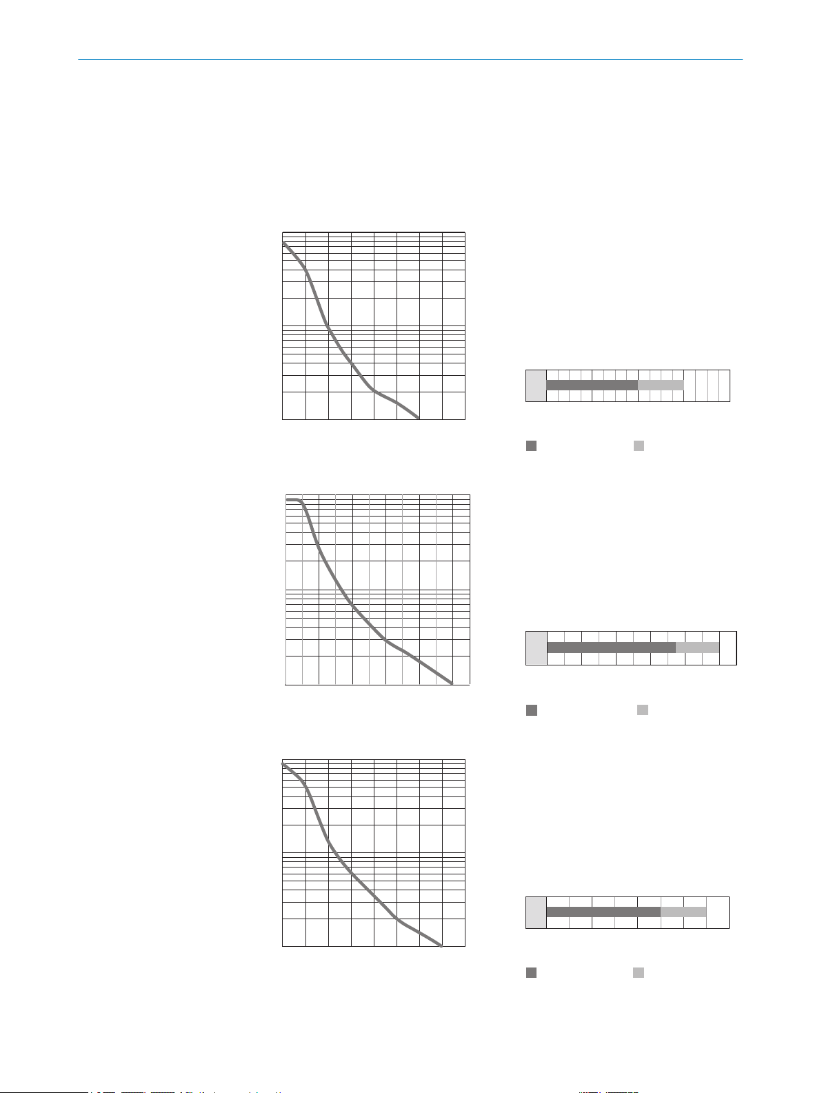
Figure 9: Sensing range area
Use see table 3, page 8 to check the function. If the switching output fails to behave in
accordance with the table, check the application conditions. See section Fault diagnosis.
3Sensitivity setting
Sensor which it is not possible to set: The sensor is adjusted and ready for operation.
8 Troubleshooting
The Troubleshooting table indicates measures to be taken if the sensor stops working.
Table 4: Troubleshooting
LED indicator/fault pattern Cause Measures
Yellow LED does not light up
even though the light beam is
aligned to the receiver and
there is no object in the path of
the beam
No voltage or voltage below
the limit values
Check the power supply,
check all electrical connec‐
tions (cables and plug connec‐
tions)
Voltage interruptions Ensure there is a stable power
supply without interruptions
Sensor is faulty If the power supply is OK,
replace the sensor
Yellow LED lights up, no object
in the path of the beam
The beam of light of a photo‐
electric through-beam sensor
hits the receiver of another
(neighboring) photoelectric
through-beam sensor
Swap the sender and receiver
arrangement at every sec‐
ond through-beam photoelec‐
tric sensor and ensure that
there is sufficient distance
between the through-beam
photoelectric sensors, see
figure 1, page 6
9 Disassembly and disposal
The sensor must be disposed of according to the applicable country-specific regula‐
tions. Efforts should be made during the disposal process to recycle the constituent
materials (particularly precious metals).
8 TROUBLESHOOTING
10 8023329 | SICK
Subject to change without notice

NOTE
Disposal of batteries, electric and electronic devices
•According to international directives, batteries, accumulators and electrical or
electronic devices must not be disposed of in general waste.
•The owner is obliged by law to return this devices at the end of their life to the
respective public collection points.
•
WEEE: This symbol on the product, its package or in this document, indi‐
cates that a product is subject to these regulations.
10 Maintenance
SICK sensors are maintenance-free.
We recommend doing the following regularly:
•Clean the external lens surfaces
•Check the screw connections and plug-in connections
No modifications may be made to devices.
Subject to change without notice. Specified product properties and technical data are
not written guarantees.
11 Technical specifications
GSE2F(S)-Xxx11 GSE2F(S)-Xxx21 GSE2F(S)-Xxx21
Sensing range 0 ... 40 mm 0 ... 150 mm 0 ... 500 mm
Sensing range max. 0 ... 60 mm 0 ... 200 mm 0 ... 700 mm
Light spot diameter/distance 10 mm / 100 mm 10 mm / 100 mm 10 mm / 100 mm
Supply voltage UBDC 10 ... 30 V3DC 10 ... 30 V3DC 10 ... 30 V3
Output current Imax.≤ 50 mA ≤ 50 mA ≤ 50 mA
Switching frequency 800 Hz6800 Hz6800 Hz6
Max. response time ≤ 0.625 ms7≤ 0.625 ms7≤ 0.625 ms7
Enclosure rating IP67 IP67 IP67
Protection class III III III
Circuit protection A, C, D11 A, C, D11 A, C, D11
Ambient operating temperature -20 °C ... +50 °C -20 °C ... +50 °C -20 °C ... +50 °C
1We recommend using compound triangular reflectors or reflective tape to ensure reliable operation. Suitable reflectors and foils can be
found in the SICK accessories range. Use of reflectors with large-scale triple structures can negatively influence functionality.
2Object with 90 % remission (based on standard white DIN 5033)
3Limit value; operation in short-circuit protection mains max. 8 A; residual ripple max. 5 Vss
5Usage category: AC-15, DC-13 (EN 60947-1)
6With light / dark ratio 1:1
7Signal transit time with resistive load
8valid for Q\ on Pin2, if configured with software
9Reference voltage DC 50 V
11 A = UB-connections reverse polarity protected
C = Interference suppression
D = outputs overcurrent and short-circuit protected
MAINTENANCE 10
8023329 | SICK
Subject to change without notice 11

11.1 Dimensional drawing
3.5 (0.14)
Ø 2.3
(0.09) Ø 2.3
(0.09)
27 (1.06)
11 (0.43)1 (0.04)
4
(0.16)
10 (0.39)
5.5 (0.22) 5.5 (0.22)
Ø 2.2
(0.09)
2.2
(0.09)
2.2
(0.09)
Figure 10: GSE2F
4.5
(0.18)
Ø 2.3
(0.09)
2.2
(0.09)
2.2
(0.09)
11 (0.43)
4
(0.16)
11 (0.43)
21 (0.83)
1 (0.04)
Figure 11: GSE2FS
11 TECHNICAL SPECIFICATIONS
12 8023329 | SICK
Subject to change without notice

Beschriebenes Produkt
G2F
GSE2F(S)
Hersteller
SICK AG
Erwin-Sick-Str. 1
79183 Waldkirch
Deutschland
Fertigungsstandort
SICK Product Center Asia Pte. Ltd.
Singapore
www.sick.com.sg
Rechtliche Hinweise
Dieses Werk ist urheberrechtlich geschützt. Die dadurch begründeten Rechte bleiben
bei der Firma SICK AG. Die Vervielfältigung des Werks oder von Teilen dieses Werks ist
nur in den Grenzen der gesetzlichen Bestimmungen des Urheberrechtsgesetzes zuläs‐
sig. Jede Änderung, Kürzung oder Übersetzung des Werks ohne ausdrückliche schriftli‐
che Zustimmung der Firma SICK AG ist untersagt.
Die in diesem Dokument genannten Marken sind Eigentum ihrer jeweiligen Inhaber.
© SICK AG. Alle Rechte vorbehalten.
Originaldokument
Dieses Dokument ist ein Originaldokument der SICK AG.
2006/42/EC
NO
SAFETY
14 8023329 | SICK
Subject to change without notice

Inhalt
12 Allgemeine Sicherheitshinweise..................................................... 16
13 Hinweise zur UL Zulassung.............................................................. 16
14 Bestimmungsgemäße Verwendung............................................... 16
15 Betriebs- und Statusanzeigen.......................................................... 16
16 Montage.............................................................................................. 17
17 Elektrische Installation..................................................................... 17
18 Inbetriebnahme................................................................................. 19
19 Störungsbehebung............................................................................ 21
20 Demontage und Entsorgung............................................................ 22
21 Wartung.............................................................................................. 22
22 Technische Daten.............................................................................. 22
22.1 Maßzeichnung........................................................................................... 23
INHALT
8023329 | SICK
Subject to change without notice 15

12 Allgemeine Sicherheitshinweise
■Lesen Sie vor der Inbetriebnahme des Geräts die Betriebsanleitung.
■
Der Anschluss, die Montage und die Konfiguration des Geräts dürfen nur
von geschultem Fachpersonal vorgenommen werden.
■
2006/42/EC
NO
SAFETY
Bei diesem Gerät handelt es sich um kein sicherheitsgerichtetes Bauteil im
Sinne der EU-Maschinenrichtlinie.
■
Bei der Inbetriebnahme ist das Gerät ausreichend vor Feuchtigkeit und Ver‐
schmutzung zu schützen.
■Die vorliegende Betriebsanleitung enthält Informationen, die während des Lebens‐
zyklus der Lichtschranke benötigt werden.
13 Hinweise zur UL Zulassung
The device must be supplied by a Class 2 source of supply.
UL Environmental Rating: Enclosure type 1
14 Bestimmungsgemäße Verwendung
Die GSE2F(S) ist eine optoelektronische Einweg-Lichtschranke (im Folgenden Sensor
genannt) und wird zum optischen, berührungslosen Erfassen von Sachen, Tieren und
Personen eingesetzt. Zum Betrieb ist ein Sender (WS) und ein Empfänger (WE) erforder‐
lich. Bei jeder anderen Verwendung und bei Veränderungen am Produkt verfällt jegli‐
cher Gewährleistungsanspruch gegenüber der SICK AG.
15 Betriebs- und Statusanzeigen
1 2
2
1
1Anzeige-LED grün: Betriebsspannung aktiv
2Empfänger: Anzeige-LED gelb: Status Lichtempfang
12 ALLGEMEINE SICHERHEITSHINWEISE
16 8023329 | SICK
Subject to change without notice

16 Montage
Lichtschranken (Sender und Empfänger) unter Verwendung geeigneter Befestigungs‐
winkel montieren (siehe die SICK Zubehörpalette). Den Sender und Empfänger anein‐
ander ausrichten.
Der Mindestabstand zwischen Sender und Empfänger beträgt:
•GSE2F(S)-xxx1xx: 24 mm
•GSE2F(S)-xxx2xx: 72 mm
•GSE2F(S)-xxx5xx: 238 mm
HINWEIS
Die Sender- und Empfängeranordnung bei jeder zweiten Einweg-Lichtschranke vertau‐
schen und sicherstellen, dass der Abstand zwischen den Einweg-Lichtschranken ausrei‐
chend ist.
Receiver (GE)
Receiver (GE)
Sender (GS)
Sender (GS)
Sender (GS)
Receiver (GE)
Abbildung 12: Anordnung mehrerer Einweg-Lichtschranken
Beachten Sie das maximal zulässige Anzugsdrehmoment von 0.1 Nm.
17 Elektrische Installation
Anschluss der Sensoren muss spannungsfrei (UV = 0 V) erfolgen. Je nach Anschlussart
sind die folgenden Informationen zu beachten:
– Steckeranschluss: Steckerbelegung beachten: Bei geöffnetem Deckel kann der
Steckverbinder horizontal und vertikal geschwenkt werden.
– Leitung: Aderfarbe
Erst nach Anschluss aller elektrischen Verbindungen die Spannungsversorgung (UV
> 0 V) anlegen bzw. einschalten.
Erläuterungen zum Anschlussschema (Tabelle Steckerbelegung):
Q = Schaltausgänge
n. c. = unbeschaltet
DC: 10 ... 30 V DC1
1Grenzwerte; Betrieb in kurzschlussgeschütztem Netz max. 8A
MONTAGE 16
8023329 | SICK
Subject to change without notice 17

Tabelle 5: Steckerbelegung
GE2F(S)
-X14xx
-X54xx
1BN + (L+) + (L+)
2- - -
3BU - (M) - (M)
4BK Q Q
BK: 0,1 mm2, AWG30
BU+BN: 0,127 mm2, AWG28
2
1
4
3
Tabelle 6: Steckerbelegung
GS2F(S)
-X14xx
-X54xx
1BN + (L+) + (L+)
2- - -
3BU - (M) - (M)
4BK n. c. n. c.
BK: 0,1 mm2, AWG30
BU+BN: 0,127 mm2, AWG28
2
1
4
3
17 ELEKTRISCHE INSTALLATION
18 8023329 | SICK
Subject to change without notice

Tabelle 7: Schaltausgang
PNP Q
(≤ 50 mA)
+ (L+)
Q
– (M)
+ (L+)
Q
– (M)
Q
(≤ 50 mA)
+ (L+)
Q
– (M)
+ (L+)
Q
– (M)
NPN Q
(≤ 50 mA)
+ (L+)
Q
– (M)
+ (L+)
Q
– (M)
Q
(≤ 50 mA)
+ (L+)
Q
– (M)
+ (L+)
Q
– (M)
18 Inbetriebnahme
1Ausrichtung
Richten Sie Sender und Empfänger aufeinander aus. Wählen Sie die Position so, dass der
rote Sendelichtstrahl auf den Empfänger trifft. Tipp: Verwenden Sie weißes Papier oder
einen Reflektor als Ausrichthilfe. Zwischen Sender und Empfänger muss eine freie Sicht‐
verbindung bestehen, d. h. der Strahlengang darf nicht von einem Objekt unterbrochen
werden. Stellen Sie sicher, dass die Optiköffnungen (Frontscheibe) der Sensoren vollstän‐
dig frei sind.
ELEKTRISCHE INSTALLATION 17
8023329 | SICK
Subject to change without notice 19

Abbildung 13: Ausrichtung GSE2F
2Schaltabstand
Die Einsatzbedingungen prüfen: den Abstand zwischen Sender und Empfänger gemäß
dem entsprechenden Diagramm anpassen [siehe Abbildung 14] (x = Schaltabstand, y =
Funktionsreserve).
Bei Verwendung mehrerer Einweg-Lichtschranken, die nebeneinander montiert werden,
wird empfohlen, die Sender-/Empfängeranordnung bei jeder zweiten Einweg-Lichtschranke
zu vertauschen und sicherzustellen, dass der Abstand zwischen den Einweg-Lichtschran‐
ken ausreichend ist. Auf diese Weise kann eine gegenseitige Beeinflussung verhindert wer‐
den [siehe Abbildung 12].
0
Abstand in mm
20 40 60 80
100
10
1
Funktionsreserve
Abbildung 14: Funktionsreserve 50 mm
0
Schaltabstand
060
1
Schaltabstand max.
Abstand in mm
20 40 8060
40
Abbildung 15: Schaltabstand 50 mm
400 80 120 160 200
100
1
Funktionsreserve
Abstand in mm
10
Abbildung 16: Funktionsreserve
150 mm
0
Schaltabstand
0 150 200
1
Schaltabstand max.
Abstand in mm
40 80 200160120
Abbildung 17: Schaltabstand 150 mm
18 INBETRIEBNAHME
20 8023329 | SICK
Subject to change without notice
Other manuals for GSE2 Flat Side
2
Table of contents
Languages:
Other SICK Accessories manuals

SICK
SICK SureSense-HTF18 User manual

SICK
SICK GSE20 User manual

SICK
SICK Bluetooth WLA16 User manual

SICK
SICK GTE20 User manual

SICK
SICK OD2000 User manual

SICK
SICK DC12-24V User manual

SICK
SICK AS30 Prime Edge User manual

SICK
SICK DT50-2 Pro User manual

SICK
SICK UM12 Series User manual

SICK
SICK WSE4F User manual
Popular Accessories manuals by other brands

NCTE
NCTE 5000 Series manual

Baxtran
Baxtran BR80 user manual

Minebea Intec
Minebea Intec Pendeo PR 6204 Series installation manual

HB Products
HB Products HBX Vapor Quality sensor Installation and configuration guide

Essentim
Essentim Scope 4 user guide

SunSetter
SunSetter Platinum Plus Series Owner's Manual & Installation Instructions