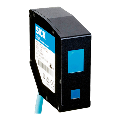
SICK Inspector I10 User manual

bRead the operating instructions before using the Inspector.
bConnection, assembly, and settings must be performed
by competent technicians.
bDo not connect external I/O signals to the Inspector while
it is powered. This may damage the device.
bMake sure that any loose cable ends are properly separated
or isolated before powering the Inspector. Otherwise the
device may be damaged.
bProtect the Inspector from moisture and dirt during
operation.
bDo not use the Inspector in areas with risk for explosion.
bTokeepIP67classication,openandclosethefront
window only with the supplied tool. Make sure that the seal
tsproperly(Flex)
bTo avoid damages, only Inspector accessory lenses offered
bySICKareallowedtobeused(Flex)
bMinimize the risk of getting dust into the device by changing
the lenses in a dust-free environment. Do not keep the
device without the front window and wipe off the front
windowbeforeyouopenit(Flex)
2D vision
8013387/YUV5∙PrintedinGermany(2016-06)
All rights reserved. Subject to change without prior notice.
QUICKSTART
Inspector I10, I20, I40
Australia
Phone +61 3 9457 0600
1800 334 802 – tollfree
Austria
Phone +43 22 36 62 28 8-0
Belgium/Luxembourg
Phone +32 2 466 55 66
Brazil
Phone +55 11 3215-4900
Canada
Phone +1 905 771 14 44
Czech Republic
Phone +420 2 57 91 18 50
Chile
Phone +56 2 2274 7430
China
Phone +86 20 2882 3600
Denmark
Phone +45 45 82 64 00
Finland
Phone +358-9-2515 800
France
Phone +33 1 64 62 35 00
Germany
Phone +49 211 5301-301
Hong Kong
Phone +852 2153 6300
Hungary
Phone +36 1 371 2680
India
Phone +91 22 4033 8333
Israel
Phone +972 4 6881000
Italy
Phone +39 02 274341
Japan
Phone +81 3 5309 2112
Malaysia
Phone +6 03 8080 7425
Mexico
Phone +52 472 748 9451
Netherlands
Phone +31 30 2044 000
New Zealand
Phone +64 9 415 0459
0800 222 278 – tollfree
Norway
Phone +47 67 81 50 00
Poland
Phone +48 22 539 41 00
Romania
Phone +40 356 171 120
Russia
Phone +7 495 775 05 30
Singapore
Phone +65 6744 3732
Slovakia
Phone +421 482 901201
Slovenia
Phone +386 591 788 49
South Africa
Phone +27 11 472 3733
South Korea
Phone +82 2 786 6321
Spain
Phone +34 93 480 31 00
Sweden
Phone +46 10 110 10 00
Switzerland
Phone +41 41 619 29 39
Taiwan
Phone +886 2 2375-6288
Thailand
Phone +66 2645 0009
Turkey
Phone +90 216 528 50 00
United Arab Emirates
Phone +971 4 88 65 878
United Kingdom
Phone +44 1727 831121
USA
Phone +1 800 325 7425
Vietnam
Phone +84 945452999
Detailed addresses and additional
representatives and agencies
at www.sick.com
Installing
Safety
Product Features
Teaching with SOPAS ET
Teaching without PC Object Locator
Detailed Inspections
Overview
SOPAS ET
Pixel counter
Counts the number of pixels within the region that has an
intensity(greyscalevalue)thatiswithinaspeciedrange.
The location of these pixels is not considered, only the
number of pixels.
Edge pixel counter
Similar to the Pixel counter, but counts the number of
edge pixels in the region. The location of the edges is not
considered, only the number of pixels.
Contour
Compares the contours in the region with the contours in
the same region on the reference object. The better the two
contours correspond, the greater is the matching score for
the inspections.
Pattern (I40)
Compares each pixel’s value in the region with the
corresponding pixel value in the reference image. The better
the pixels correspond, the greater is the matching score for
the inspections.
<4 px
When teaching an Inspector which has not previously been
congured,theresultingreferenceobjectwillhaveanobject
locatorthatcoverstheentireeldofview.
1. PlaceanobjectinfrontoftheInspectorandconnectin2
to+24V.
Afterabout3secondstheFunctionLEDstartstoash.
3. Click Teach reference object.
The Inspector captures a reference image of the object
and displays it.
3. Findtheeldofviewwiththehelpofforexampleapen.
WhentheInspectordetectsmovementsintheeldof
view,theFunctionLEDchangescolortoblue.
5. Add detailed inspection over the parts of the object to be
inspected.
4. Disconnectin2fromthepower.
The Inspector will now use the latest captured image as
reference image.
6. TesttheinspectionintheLiveimageandadjustthe
settings if necessary.
5. The Inspector will then automatically switch to Run mode
and start inspecting
When the inspections are accurate enough, switch to Run to
put the Inspector in operation. When asked, you should save
thesettingsintheInspector’sashmemorytoassurethat
they will be remembered if the power should be disconnected.
1. Mount the Inspector at an appropriate distance from the
objects to be inspected.
SOPASETisthePCapplicationthatisusedformonitoringand
conguringtheInspector.ItcanbeinstalledonanyPC,and
then be used for accessing any Inspector that is connected to
the same network as the PC.
ToconnecttoanInspectorfromSOPASET.
1. Make sure that the Inspector is powered, and connected
to the PC or to the same network as the PC.
2. StartSOPAS ET.
3. In the Device search pane, double-click on the Inspector in
the list of available devices.
An object locator is used when teaching the Inspector to
recognisetheobjectstoinspect.Eachreferenceobjectcan
not have more than one object locator.
The Inspector locates an object by recognising the contours
of it. The contours that are used are highlighted in green in
SOPASET.
bAdjust the amount of contours to learn with the Edge
strength slider on the Object locator tab.
bAdjust the size, location, shape, and rotation of the object
locator so that it covers the object properly. Use masks
to mask out areas that normally varies on the object, for
example if they have different labels .
OK
Enoughamount
of learned
contours
Bad
Too few
contours
Bad
Too many con-
tours, as well as
contours on the
background
Match Settings
bIf objects are never rotated, deselect Allow rotation to
improve both robustness and speed.
bTo verify that objects are not rotated more than a small
amount, select Allow rotation and set the max rotation to a
small amount.
bIf objects are always of the same size and at the same
distance from the Inspector, deselect Allow scaled objects to
improve both robustness and speed.
An Inspector with ring
light may need to be
mounted at a small angle
to avoid too much reexes.
An Inspector with Dome
light should be aligned
with the objects, at a
distance of approximately
50 mm to get optimal
effect of the dome lighting.
2. ConnecttheEthernetconnectorontheInspectortoa
network,ordirectlytoanEthernetconnectoronaPC.
4. Ifnecessary,adjustthesizeandlocationoftheobject
locator, and the amount of highlighted contours.
bBright contours are more important than dim contours.
bAvoid highlighting contours outside the object.
bIt is not necessary to get bright contours everywhere on
the important contours.
Note: TheEdgestrengthsettingforEdgepixel
counter and Contour inspections is common
for all inspections of these types for a reference
object.
The Inspector
rst locates the
object...
... and then inspects
details on the found
object.
Detailed
inspection
Object
locator
bHigh-speed object inspection
bRobust pattern match algorithm to locate objects indepen-
dent of position, rotation and scale
bMulti-feature inspections /object
bMulti-reference object teaching
bEasy-to-usecongurationinPC
bEmulator,log,statisticsandrecordforproductioncontrol
bIndustrialEthernetformonitoringovernetwork
bExchangeablelens(Flex)
bOutputsbylogicalexpressions(I20,I40)
bInputandoutputextensionsviaI/Obox(I20,I40)
bStoreinspectedimagestoremoteFTPserver(I40)
bProvidedetailedinspectionresultsoverEtherNet/IP(I40)
bLiveimage/log/statisticsviewandreferenceobjectchange
via external Viewer
The Inspector inspects objects in the following way:
bFirst,itlocatestheobjectintheview.
bAfterthat,itinspectsdetailsontheobjecttondout
whether the object is OK or not.
All passed Detail failed Not located
On
On
On
Off
Eachinspectiongivesoneofthefollowingresults:
Not located The object was not located, or a detailed
inspection was out of view
Detail failed The object was located but at least one of the
detailed inspections failed.
All passed The object was located and all detailed inspec-
tions passed as well.
The Inspector provides the inspection result in the following
ways, depending on the model:
I10 3xedbuilt-indigital
outputs
out1–Notlocated
out2–Detailfailed
out3 – All passed
I20,
I40
3 built-in digital outputs
16 additional digital
outputs with I/O exten-
sion box
Congurable,using
Outputs by logical
expressions
(DefaultsameasI10)
I40 EtherNet/IP Detailed inspection
results
1. SwitchtheInspectortoEditmodebyclickingEdit in the
main view.
2. PlaceanobjectinfrontoftheInspector,andadjustfocus
andexposuresothattheLiveimageissharpandbright.
2. Adjustfocusbyturningthefocusscrew.
ThefastertheFunctionLEDashes,thebetterthefocus.
±4 px
The device now appears in the New Project pane. Double-click
on the device to open the device window and start the
conguration.
bIf the Inspector is not listed in the Device search pane, click
Search settingstonetunethesearchcriteria.
bIf the connection to the device is not working, change the
IP settings of the device via the edit icon on the device tile.
AlsomakesurethattherequiredSOPASDeviceDriver(SDD)
is installed: Select the Device catalog tab and add the SDD via
the Conguration button.
Formoreinformationabouttheconnection,seetheonline
help.
3. If the input or output signals are used, or if an external
lighting will be used, connect those devices to the
Inspector’sPowerconnector( B ).
Note: Make sure that the loose ends of the I/O cable
are separated before powering the Inspector.
4. ConnecttheInspectortoa24VDCpowersupply( B ).
5. IfaPCshouldbeusedforconguringtheInspector,
installthecongurationsoftwareSOPASETv3.x.SOPAS
ETisavailablefordownload,freeofcharge,fromthe
Softwarenderatwww.sick.com.
SICK uses standard IPtechnologyforitsproducts,e.g.IOLink,
industrial PCs. The focus here is on providing availability of
products and services.
SICKalwaysassumesthattheintegrityandcondentialityof
data and rights involved in the use of the above-mentioned
products are ensured by customers themselves.
In all cases, the appropriate security measures, e.g. network
separation,rewalls,antivirusprotection,patchmanagement,
etc., are always implemented by customers themselves,
according to the situation.
Disclaimer
EN

Power In/Out
(12 pin M12)
Ethernet
(4 pin M12)
C
G
H
LED Color Description
Data Yellow EthernetData
Link Green EthernetLink
Function Multi See separate table.
On Green Power On
Lens Distance ring Working distanse
Focallength16mm Black(3mm)
+Silver(1,5mm)
100mm...140mm
Focallength16mm Black(3mm) 140mm...600mm
Focallength16mm Silver(1,5mm) 600 mm ... ∞
Focallength10mm Silver(1,5mm) 50mm...120mm
Focallength10mm None 120mm...∞
Focallength8mm Silver(1,5mm) 50 mm ... ∞
Focallength6mm None 50 mm ... ∞
Focallength4.3mm Black(3mm) 50 mm ... ∞
Function LED Color Description
Run & Edit
mode
Blue Notlocated.
Red Detail failed.
Green All passed.
Off Noinspection.
External teach Flashing Image focus. Higher
frequency means better
focus.
Green Nomotionineldofview.
Blue Motionineldofview.
White Storing reference image in
ash.
Anytime Red, slow
ashing
Fatalerror.
B
Viewer or PC
with Ethernet
I/O extension
box
EtherNet/IP bus
Inspector
24 V DC
Power supply
Output signals (1..3)
Screw terminal
External lighting
Switch for
external teach
Encoder
Photoelectric switch
External object
selection (1...4)
Connecting the Inspector
Technical data
Connectors
Inspector LEDs
A Dimensional drawings
bWindowsXPProfessional(ServicePack2),Windows
VistaBusinessEdition(32/64bit)servicepack1,or
Windows7Professional(32/64bit)
bPentium III 550MHz or higher
ForsimulateddevicemodeaPentium42.5GHzor
higher should be used
b512MBofRAM(recommended1024MB)
b1024x768orhigherscreenresolution,minimum
256colors(recommended65536colors)
b570 MB free hard disk space
bEthernet:100MBit/srecommended
bRecommendedFTPserverstousewithStoreimagesto
FTP:Filezilla,MicrosoftIIS
26
(1.02)
53 (2.09)
100.1 (3.94)
16
(0.63)
16
(0.63) 74 (2.91)
38
(1.50)
58.5 (2.30)
Ø 82.6
(3.25)
58.5 (2.30)
38
(1.50)
53 (2.09)
45
(1.77)
3 x M4
70 (2.76)
100 (3.94)
Working
distance
Near Far
Working
distance
Near Far
53 (2.07)
78 (3.07)
36 (1.42)
14 (0.55)
28 (1.10)
M5 (4x)
Ø 4.3 (3X)
(0.17)
45 (1.77)
4 (0.16)
70 (2.76)
R4 (4x)
(0.16)
R4
(0.16)
R4
R4
3
(0.12)
A-A 90 (3.54)
4
M46x0.75 ø 4.5 (2x) (0.18)
ø 8 (2x) (0.31)
4.4 (2x) (0.17)
0.5x45°
(0.02)
15
(0.59) 50 (1.97)
76 (2.99)
ø 38
(1.50)
A
A
2 (0.08)
Ø 4.3 (6x)
(0.17)
70 (2.76)
78 (3.07)
28.5
(1.12)
22.5
(0.89)
22.5
(0.89)
R4 (6x)
(0.16)
1.5 (2x)
(0.06)
5 (0.20)
53 (2.09)
UNC 1/4-20
M6
3 (0.12)
22
(0.87)
32
(1.26)
40 (1.57)
4.5 (2x)
(0.18)
R16
(0.63)
R4 (2x)
(0.16)
48 (1.89)
90°
R2.5
(0.10)
Inspector
Brackets
Inspector angle
bracket
Inspectorlight/lteradapter Inspector universal adapter
System Requirements
Service and Maintenance Further Information
The Inspector contains no user serviceable parts inside.
bCheck screw connections and connectors at regular
intervals.
bClean the housing with a soft cloth, dry or dampened
with a mild water diluted cleaning agent without powder
additives.
ColorsarevalidforcabletypeDOL-1212-…
Make sure that the loose
ends of the I/O cable are
separated before turning
on the device.
2
1
34
2
10
1
9
8
12
3
4
11
5
6
7
1
2
3
4
Rx+
Rx-
Tx+
Tx-
24V±20%DC
out2
0 V
out3
in2/externalteach
in4/encoder
reserved
out1
trigger out, 5 V
reserved
in3/trigger
in1
1
2
3
4
5
6
7
8
9
10
11
12
blu
brn
wht
grn
pnk
yel
black
grey
red
violet
grey/pink
red/blue
D
E F
Exchange the lens
Mounting lters Mounting Dome lighting
VSPI-
1R111
I10
Standard
VSPI-
1D111
I10
Dome
VSPI-
2F111
I20
Flex
VSPI-
2D111
I20
Dome
VSPI-
2F121
I20-UV
Flex
VSPI-
2F141
I20-IR
Flex
VSPI-
4F2111
I40
Flex
VSPI-
4F2311
I40-LUT
Flex
VSPI-
4F2411
I40-IR
Flex
Working distance
50...∞mm
Working distance, internal
illumination
50...200mm
50 mm
Field of view, internal illu-
mination
20x20...72x72mm
2
30 x 30 mm
2
22x15...79x58mm
2
Optics
Exchangeable
Max performance
250fps
Typical performance (1)
40fps
Toolset Object locator
Pixel count, edge pixel count, contour
Pattern
Number of inspections
32regions
Reference images 16 objects
32objects
Offline support Emulator
Production control
- Operator interface SOPAS, Viewer
- Data store and
retrieve
30 images device log
Record images on PC
StoreimagestoFTP
- PLC communication EtherNet/IP
- I/O box extension 4xinputsforobjectselection
5x inputs for object selection
16x outputs
Resolution 384x384pixels
640x480pixels
Light source Whiteringlight:6highpowerLEDs
White Dome light
UV ring light, 385 nm
IR ring light, 850 nm
- LED class Riskgroup1(lowrisk,
EC62471:2006)
Riskgroup0(lowrisk,
EC62471:2006)
Spectral response Approx.400...750nm
NearUV<400nm
Approx.370...900nm
Supply voltage VS 24VDC±20%
- Ripple <5Vpp
- Current consumption <450mAwihoutload
Digital outputs 3outputs24V(B-type)
- Outputs currents 100 mA
- Default outputs Noobjectlocated,allpass,anyfail
- Configurable outputs Outputs by logical expressions
StoreimagestoFTPoverflow
Control of external light 5VTTL
Digital inputs 4inputs24V
- Configurable inputs Externaltrigger,encoder,external
teach, reference object selection
- Max encoder
frequency
40kHz
Interface 100MbEthernet
Ambient temperature (2) Operation:0…45°C
Storage:-20°C…70°C
Housing material Aluminum
- Window material PMMA(plastic)
Glass
Weight 350 g
400g
Enclosure rating IP 67
Mechanical chock and
vibration load
EN60068-2-27,EN60068-2-6
Device specific accessories (3)
- Lenses, focal length 4.3mm
6 mm
8 mm
10 mm
16 mm
- Glass front filters (4) Red(>588nm)
Green(544±53nm)
Blue(468±62nm)
IR(>730nm)
- Dome Optimal for 50 mm working distance
- I/O extension box 4inputs,8outputs
- I/O module 2extradigitalinputs
8 extra digital outputs
- Viewer Liveimage/log/statisticsviewand
reference object change
(1)Fullresolution,fullrotationinhigh-speedmode
(2)Rel.humidity:35...85%,95%atstorage
(3)Fullaccessorylistatwww.sick.com
(4)>60%transmission
0
100
200
300
400
500
600
0 100 200 300 400 500 600 700 800 900 1000
f = 4.3 mm
f = 6 mm
f = 8 mm
f = 10 mm
f = 16 mm
0
100
200
300
400
500
600
0 100 200 300 400 500 600 700 800 900 1000
f = 6 mm, horiz.
f = 6 mm, vert.
f = 8 mm, horiz.
f = 8 mm, vert.
f = 10 mm, horiz.
f = 10 mm, vert.
f = 16 mm, horiz.
f = 16 mm, vert.
ToreplacethestandardlensoftheInspectorFlex:
1. OpenthefrontwindowoftheInspectorFlexusingthe
large end of the supplied tool.
2. Removethestandardlensbyusingthesmallendof
the tool.
3. Attach the new lens. Refer to the graph for the correct
number of distance rings to use.
4. AttachthefrontwindowagaintotheInspectorFlex.
Toreplacethefrontwindowwithafrontglasscolorlter:
1. OpenthefrontwindowoftheFlexhousingusingthe
large end of the supplied tool.
2. AttachthefrontglasscolorltertotheFlexhousing
by using the supplied tool.
To replace the front window with the Dome:
1. OpenthefrontwindowoftheFlexhousingusingthe
large end of the supplied tool.
2. AttachtheDometotheFlexhousingbyhand.
1.
1. 1.
2.
2. 2.
3.
TheoreticalFOVsize(384x384pixels)
TheoreticalFOVsize(640x480pixels)
Horizontal/verticalFOVsize[mm]
Objectdistance[mm]
Objectdistance[mm]
FormoreinformationontheInspector,pleaserefertothe
Operating Instructions at www.sick.com, or the online help in
SOPASET.Licensetextsarefoundatwww.sick.com/licensetexts.
Forsupportissues,pleasecontactyourlocalsalesofce.
More product and order information is found on:
www.sick.com

Ein
bLesenSiedieseAnweisungenvorBenutzungdesInspectors.
bAnschlüsse,InstallationundKongurationdürfennurdurch
ausgebildete Techniker ausgeführt werden.
bFührenSiealleAnschlüssenuraneinemspannungsfreien
Gerätaus.AnsonstenkanneszuBeschädigungenkommen.
bTrennen und isolieren Sie alle losen Kabelenden, bevor
Sie die Spannungsversorgung des Inspector einschalten.
AnsonstenkanneszurBeschädigungdesGerätskommen.
bSchützenSiedenInspectorwährenddesBetriebsvor
FeuchtigkeitundVerschmutzung.
bBenutzenSiedenInspectornichtinexplosionsgefährdeten
Bereichen.
bÖffnenundschließenSiedieFrontscheibenurmitdem
mitgeliefertenWerkzeug,umdenSchutzgemäßIP67zu
gewährleisten.StellenSiesicher,dassdieDichtungkorrekt
sitzt(Flex).
bUmSchädenzuvermeiden,verwendenSieausschließlich
die als Zubehör zum Inspector von SICK angebotenen und
zugelassenenObjektive(Flex).
bWechseln Sie das Objektiv nur in staubarmer Umgebung, um
dasEindringenvonStaubundSchmutzindenVision-Sensor
zuvermeiden.EntfernenSiedieFrontscheibedesGeräts
nurfürkurzeZeit,undwischenSiedieFrontscheibeab,
bevorSiesieöffnen(Flex).
2D-Vision
8013387/YUV5∙GedrucktinDeutschland(2016-06)
Alle Rechte vorbehalten. Irrtümer und Änderungen vorbehalten.
SCHNELLSTARTANLEITUNG
Inspector I10, I20, I40
Installation
Sicherheit
Produkteigenschaften
Einlernen mit SOPAS ET
Lernen ohne Verwendung des Computers Objektnder
Detailprüfungen
Übersicht
Pixelzähler
DerPixelzählerzähltineinerbestimmtenRegionallePixel,
derenGrauwert(Helligkeit)innerhalbeinesdenierten
Grauwertbereichesliegt.DieLagederPixelwirdnicht
berücksichtigt, nur die Anzahl.
Kantenpixelzähler
DerKantenpixelzählerarbeitetähnlich,zähltjedochdie
KantenpixeleinerbestimmtenRegion.DieLagederKanten
wird nicht berücksichtigt, nur die Anzahl der Pixel.
Kontur
Die Konturen in einer bestimmten Region werden mit den
Konturen derselben Region im Referenzbild verglichen.
Je höher die Übereinstimmung ist, desto besser ist die
Prüfquote.
Muster (I40)
Der Wert jedes Pixels in der Region wird mit den entspre-
chenden Pixelwerten im Referenzbild verglichen. Je besser
sich die Pixel decken, desto höher ist der Übereinstim-
mungswert für diese Prüfungen.
<4 px
1. SchaltenSiedenInspectorindenEinrichtungsmodus,
indem Sie im Hauptfenster auf Einrichten klicken.
2. LegenSieeinObjektvordenInspector,richtenSieihnso
aus, dass das Objekt im Bild sichtbar ist und stellen Sie
BelichtungundFokussoein,dassdasLive-Bildhellund
scharf ist.
WennSiedasLernenmiteinemnichtkonguriertenInspector
durchführen, verwendet das neue Referenzobjekt einen
Objektnder,derdasgesamteSichtfeldabdeckt.
1. LegenSieeinObjektvordenInspector,undverbindenSie
denEingangin2mit+24V.
Nachetwa3sbeginntdieLEDFunctionzublinken.
3. Klicken Sie auf Referenzobjekt lernen.
2. StellenSiedenFokusmitHilfederFokusschraubeein.
JeschnellerdieLEDblinkt,destobesseristderFokus
eingestellt.
Der Inspector nimmt ein Referenzbild vom Objekt auf und
zeigt es an.
3. Zum Ausrichten des Objekts vor der Kamera suchen Sie
das Sichtfeld, zum Beispiel mit einem Stift.
Wenn der Inspector Bewegungen im Sichtfeld registriert,
wechseltdieFarbederLEDFunctionnachBlau.
5. FügenSieDetailprüfungenandenentsprechenden
Stellen des Objekts hinzu.
4. TrennenSiedieSpannungvomEingangin2.
Der Inspector verwendet jetzt das zuletzt aufgenommene
Bild als Referenzbild.
6. TestenSiediePrüfungenimLive-BildundkorrigierenSie
dieEinstellungen,wennnötig.
5. Der Inspector schaltet anschließend automatisch in den
Betriebsmodus um und startet die Prüfung.
Wenn die Testprüfungen erfolgreich sind, wechseln Sie in
den Betriebsmodus, um die Prüfungen zu starten. Wenn das
ProgrammSiedanachfragt,speichernSiedieKonguration,
damitderInspectordieseEinstellungennachTrennungvom
Stromnetz und Wiedereinschalten erneut verwenden kann.
1. Bringen Sie den Inspector im geeigneten Abstand zu den
Prüfobjekten an.
DerObjektndererkenntdieaktuellePositiondesObjektes
bei jeder einzelnen Prüfung. Jedes Referenzobjekt kann
höchstenseinenObjektnderverwenden.
DerInspectorndeteinObjekt,indemerdessenKonturen
erkennt. Die Konturen, die verwendet werden, werden in
SOPASETgrünhervorgehoben.
bStellen Sie die Anzahl der zu lernenden Konturen mit dem
Schieberegler Kantenstärke auf dem Register Objektnder
ein.
bStellenSieGröße,Lage,FormundRotationsoein,dass
das Objekt jederzeit erfasst wird. Verwenden Sie Masken,
um bestimmte Bereiche auszuschließen.
OK
Ausreichende
Anzahl von
gelernten
Konturen
Schlecht
Zu wenige
Konturen
Schlecht
Zu viele
Konturen
und Konturen
auf dem
Hintergrund
Einstellungen für den Objektnder
bWenn keine gedrehten Objekte auftreten, deaktivieren
Sie die Option Rotation erlauben,umGenauigkeitund
GeschwindigkeitderPrüfungheraufzusetzen.
bUm sicherzustellen, dass Objekte nur leicht gedreht sind,
aktivieren Sie die Option Rotation erlauben,undwählenSie
einen kleinen Wert.
bWennObjekteimmerindergleichenGrößeundim
gleichen Abstand zum Inspector erwartet werden,
deaktivieren Sie die Option Andere Objektgrößen erlauben,
umGenauigkeitundGeschwindigkeitderPrüfung
heraufzusetzen.
Ein Inspector mit Ring-
beleuchtung muss ggf.
mit einem achen Winkel
angebracht werden, um
Oberächenreexionen zu
vermeiden.
Ein Inspector mit Dombe-
leuchtung sollte direkt auf
die Objekte gerichtet sein,
mit etwa 50 mm Abstand,
um die Dombeleuchtung
optimal zu nutzen.
2. VerbindenSiedieEthernet-SchnittstelledesInspectormit
einemNetzwerkoderdirektmiteinemComputer.
3. WennEingangs-oderAusgangssignaleodereineexterne
Beleuchtung verwendet werden, verbinden Sie diese mit
dem Anschluss PowerdesInspector( B ).
4. Wennnötig,ändernSieGrößeundLagedesObjektn-
ders,undwählenSiedieAnzahlmarkierterKonturen.
bHelle Konturen sind wichtiger als dunkle Konturen.
bVermeiden Sie Markierungen außerhalb des Objekts.
bEsistnichtnotwendig,dassallewichtigenKonturen
hell sind.
Hinweis: DieEinstellungderKantenstärkegilt
gemeinsam für alle Prüfungen zu einem
Referenzobjekt.
Der Inspector
ndet zuerst das
Objekt ...
... und führt dann Detail-
prüfungen am gefundenen
Objekt durch.
Detailprüfung
Objekt-
nder
bPrüfungenmithoherGeschwindigkeit
bZuverlässigerMustervergleichunabhängigvonPosition,
DrehwinkelundGröße
bSimultane Mehrfachprüfung
bMehrere Referenzobjekte
bBenutzerfreundlicheKongurationamComputer
bEmulation,Protokollierung,StatistikundAufzeichnungzur
Produktionskontrolle
bIndustriellesEthernetfürdieÜberwachungimNetzwerk
bWechselobjektiv(Flex)
bLogischverknüpfteAusgänge(I20,I40)
bI/O-BoxzurErweiterungderEingängeundAusgänge(I20,I40)
bGeprüfteBilderaufRemote-FTP-Serverspeichern(I40)
bErgebnissederObjektprüfungüberEtherNet/IPbereitstel-
len(I40)
bExterneAnzeigezurBetrachtungvonBildern,Statistikenund
LOG-DateienoderzureinfachenÄnderungdesReferenzobjektes.
So prüft der Inspector:
bZuerst wird das Objekt im Sichtfeld gesucht.
bAnschließend folgen Detailprüfungen, um festzustellen, ob
das Objekt fehlerfrei ist oder nicht.
Alle OK Detailfehler Nicht
gefunden
Ein
Ein
Aus
JedeObjektprüfunghateinesderfolgendenErgebnisse:
Nicht gefunden Das Objekt wurde nicht gefunden, oder eine
Detailprüfung lag außerhalb des Sichtfeldes.
Detailfehler Das Objekt wurde gefunden, aber mindes-
tenseineObjektprüfunglieferteeinenFehler.
Alle OK Das Objekt wurde gefunden, und alle
Objektprüfungen sind fehlerfrei abgelaufen.
DerInspectorliefertdasErgebnisderPrüfungjenachModell
folgendermaßen:
I10 3 feste, interne digitale
Ausgänge
out1–Nichtgefunden
out2–Detailfehler
out3 – Alle OK
I20,
I40
3 interne digitale
Ausgänge
16zusätzlichedigitale
AusgängemitI/O-Box
Mit Hilfe von Aus-
gangsfunktionen durch
logische Verknüpfungen
kongurierbar
(StandardwieI10)
I40 EtherNet/IP Ergebnisseder
Objektprüfung
±4 Pxl
SOPAS ET
SOPASETisteinePC-AnwendungzurKongurationund
Überwachung des Inspector. Die Anwendung kann auf jedem
beliebigen PC installiert werden und bietet Zugang zu jedem
beliebigenInspector,dermitdemselbenNetzwerkverknüpft
ist wie der PC selbst.
VerbindungmiteinemInspectorüberSOPASETherstellen.
1. Stellen Sie sicher, dass der Inspector mit Strom versorgt
wirdundmiteinemPCbzw.mitdemselbenNetzwerkwie
der jeweilige PC verknüpft ist.
2. StartenSieSOPAS ET.
3. Doppelklicken Sie im Register GerätesucheinderListeder
verfügbarenGeräteaufdenInspector.
DasGerätwirdnunimRegisterNeues Projekt angezeigt. Dop-
pelklickenSieaufdasGerät,umdasGerätefensterzuöffnen
unddieKongurationzustarten.
SICK verwendet für seine Produkte Standard-IP-Technologie,
mitunterfürIO-LinkundIndustrierechner.Dabeiliegtder
FokusinsbesondereaufderVerfügbarkeitderProdukteund
Dienstleistungen.
SICKsetztstetsvoraus,dassIntegritätundVertraulichkeitder
DatenundRechterundumdieNutzungderobenaufgeführ-
ten Produkte von dem Kunden selbst sichergestellt werden.
InallenFällensindentsprechendeSicherheitsmaßnahmen,
darunterNetzwerktrennungen,Firewalls,Virenschutz,
Patch-Managemenet usw. je nach Situation stets vom Kunden
selbst zu treffen.
Haftungsausschluss Hinweis:StellenSiesicher,dassdielosenEndendes
I/O-Kabels voneinander getrennt sind, bevor Sie
dasGeräteinschalten.
4. VerbindenSiedenInspectoramAnschlussPower mit
einemNetzteil24VDC( B ).
5. FallsSiedenInspectormitHilfeeinesPCskongurieren
möchten,installierenSiedieKongurationssoftware
SOPASETv3.x.SOPASETkannüberdenSoftwarender
auf www.sick.com kostenlos heruntergeladen werden.
bWenn der Inspector nicht im Register Gerätesuche aufgelistet
ist, klicken Sie auf Sucheinstellungen , um die Suchkriterien zu
verfeinern.
bSolltedieVerbindungmitdemGerätnichteinwandfreifunk-
tionieren,passenSiebittedieIP-EinstellungendesGeräts
überdasSymbolBearbeitenimGerätemenüan.StellenSie
zudemsicher,dassderbenötigteSOPASDeviceDriver(SDD)
installiertist:WählenSiedasRegisterGerätekatalog aus und
fügenSiedenSDDüberdieSchaltächeKonguration hinzu.
WeitereInformationenzumThemaAnschlussndenSieinder
Online-Hilfe.
Australia
Phone +61 3 9457 0600
1800 334 802 – tollfree
Austria
Phone +43 22 36 62 28 8-0
Belgium/Luxembourg
Phone +32 2 466 55 66
Brazil
Phone +55 11 3215-4900
Canada
Phone +1 905 771 14 44
Czech Republic
Phone +420 2 57 91 18 50
Chile
Phone +56 2 2274 7430
China
Phone +86 20 2882 3600
Denmark
Phone +45 45 82 64 00
Finland
Phone +358-9-2515 800
France
Phone +33 1 64 62 35 00
Germany
Phone +49 211 5301-301
Hong Kong
Phone +852 2153 6300
Hungary
Phone +36 1 371 2680
India
Phone +91 22 4033 8333
Israel
Phone +972 4 6881000
Italy
Phone +39 02 274341
Japan
Phone +81 3 5309 2112
Malaysia
Phone +6 03 8080 7425
Mexico
Phone +52 472 748 9451
Netherlands
Phone +31 30 2044 000
New Zealand
Phone +64 9 415 0459
0800 222 278 – tollfree
Norway
Phone +47 67 81 50 00
Poland
Phone +48 22 539 41 00
Romania
Phone +40 356 171 120
Russia
Phone +7 495 775 05 30
Singapore
Phone +65 6744 3732
Slovakia
Phone +421 482 901201
Slovenia
Phone +386 591 788 49
South Africa
Phone +27 11 472 3733
South Korea
Phone +82 2 786 6321
Spain
Phone +34 93 480 31 00
Sweden
Phone +46 10 110 10 00
Switzerland
Phone +41 41 619 29 39
Taiwan
Phone +886 2 2375-6288
Thailand
Phone +66 2645 0009
Turkey
Phone +90 216 528 50 00
United Arab Emirates
Phone +971 4 88 65 878
United Kingdom
Phone +44 1727 831121
USA
Phone +1 800 325 7425
Vietnam
Phone +84 945452999
Detailed addresses and additional
representatives and agencies
at www.sick.com
DE
2
Ø 4,3 (6x)
70
78
28,5
22,522,5
R4 (6x)
1,5 (2x)
553
UNC 1/4-20
M6
(3)
22
32
40
4,5 (2x)
R16
R4 (2x)
48
90°
R2,5
Working
distance
Near Far
Working
distance
Near Far
26
53
100,1
16
16 74
38
58,5
Ø 82,6
58,5
38
53
45
3 x M4
70
100
53
78
36
1428
M5 (4x)
Ø 4,3 (3X)
45
4
70
R4 (4x)
R4
R4
R4
3
A-A 90
4
M46x0,75 ø 4,5(2x)
ø 8(2x)
4,4 (2x)
0,5x45°
15 50
76
ø 38
A
A
H
B Anschlüsse
Technische Daten
A Maßbild
bWindowsXPProfessional(ServicePack2)oderWindows
VistaBusinessEditionServicePack1(32/64Bit)oder
Windows7Professional(32/64Bit)
bPentium III 550MHz oder höher
Pentium4mit2,5GHzoderhöherfürEmulatorbetrieb
b512MBRAM(1024MBempfohlen)
bBildschirmauösung1.024×768oderhöher,
mindestens256Farben(empfohlen65536Farben)
bCD-ROM-Laufwerk
b570MBverfügbarerFestplattenspeicherplatz
bEthernet:Empfehlung,100Mbit/s
bEmpfohleneFTP-ServerzumSpeichernvonBildernauf
FTP:Filezilla,MicrosoftIIS
Inspector
Halterungen/Adapter
Montagewinkel
AdapterfürBeleuchtung/Filter Universaladapter
Systemanforderungen
Wartung und Pege Weitere Informationen
In dem Inspector sind keinerlei Komponenten unterge-
bracht, die von dem Benutzer gewartet werden können.
bÜberprüfen Sie Schraub- und Steckanschlüsse in
regelmäßigenAbständen.
bReinigenSiedasGehäusemiteinemweichenTuch.
Dieses kann entweder trocken sein oder mit einer milden
ReinigungslösungohnePulverzusätzebenetztwerden.
VSPI-
1R111
I10
Standard
VSPI-
1D111
I10
Dome
VSPI-
2F111
I20
Flex
VSPI-
2D111
I20
Dome
VSPI-
2F121
I20-UV
Flex
VSPI-
2F141
I20-IR
Flex
VSPI-
4F2111
I40
Flex
VSPI-
4F2311
I40-LUT
Flex
VSPI-
4F2411
I40-IR
Flex
Nenn-Tastweite
50...∞mm
Nenn-Tastweite, interne
Beleuchtung
50...200mm
50 mm
Sichtfeld, interne Beleuchtung
20x20...72x72mm
2
30 x 30 mm
2
22x15...79x58mm
2
Optik
Austauschbar
Maximalleistung
250fps
Regelleistung (1)
40fps
Werkzeuge Object locator
Pixelzähler,Kantenpixelzähler,Kontur
Muster
Anzahl Prüfungen
32Regionen
Referenzbilder 16 Objekte
32Objekte
Offlineunterstützung Emulator
Produktionssteuerung
- Bediener-
Programmoberfläche
SOPAS, Viewer
- Datenspeicherung und
-abruf
30BilderimGeräteprotokoll
Bilder auf Computer speichern
BilderaufFTPspeichern
- Kommunikation mit der
Steuerung
EtherNet/IP
- I/O-Box 4EingängefürdieObjektauswahl
5EingängefürdieObjektauswahl
16Ausgänge
Auflösung 384x384Pixel
640x480Pixel
Beleuchtung Weiße Ringbeleuchtung: 6 leistungsstarke
LEDs
Weiße Dombeleuchtung
UV-Ringbeleuchtung, 385 nm
IR-Ringbeleuchtung, 850 nm
- LED-Klasse Risikogruppe1(geringesRisiko,
EC62471:2006)
Risikogruppe0(geringesRisiko,
EC62471:2006)
Farbempfindlichkeit Ca.400...750nm
NahesUV<400nm
Ca.370...900nm
Versorgungsspannung VS 24VGleichstrom±20%
- Welligkeit <5Vpp
- Stromaufnahme
<450mAunbelastet
Digitale Ausgänge 3Ausgänge,24V(TypB)
- Ausgangsstrom IA 100 mA
- Standardausgänge Kein Objekt gefunden, alle OK, beliebige
fehlerhaft
- Konfigurierbare Ausgänge Ausgangsfunktionen durch logische
Verknüpfungen
Überlauffür„BilderaufFTPspeichern“
Steuerung des externen Lichts 5VTTL
Digitale Eingänge 4Eingänge,24V
- Konfigurierbare Eingänge ExternerTrigger,Encoder,externesLernen,
Auswahl des Referenzobjekts
- Max. Encoderfrequenz 40kHz
Schnittstelle 100MBEthernet
Ambient temperature (2) Betriebstemperatur:0…45°C
Lagertemperatur:-20°C…70°C
Gehäusematerial Aluminium
- Material der Frontscheibe PMMA(Kunststoff)
Glas
Gewicht 350 g
400g
Schutzart IP 67
Mechanische Stoßfestigkeit
und Schwingbelastung
EN60068-2-27,EN60068-2-6
Gerätespezifisches Zubehör (3)
- Objektive, Brennweite 4,3mm
6 mm
8 mm
10 mm
16 mm
- Frontglasfilter (4) Rot(>588nm)
Grün(544±53nm)
Blau(468±62nm)
IR(>730nm)
- Dom Optimal für Tastweite von 50 mm
- I/O-Box 4Eingänge,8Ausgänge
- I/O-Modul 2zusätzlichedigitaleEingänge
8zusätzlichedigitaleAusgänge
- Viewer Betrachtung von Bildern, Statistiken und
LOG-DateienoderzureinfachenÄnderung
des Referenzobjektes
(1) Volle Auflösung, volle Rotation im Hochgeschwindigkeitsmodus
(2)Rel.Luftfeuchtigkeit:35...85%,95%beiLagerung
(3) Komplette Zubehörliste auf www.sick.com
(4)>60%Übertragung
Power In/Out
(12-polig, M12)
Ethernet
(4-polig, M12)
C
G
LED Farbe Beschreibung
Data Gelb EthernetDatenübertr.akt.
Link Grün EthernetVerbindungaktiv
Function Mehrfach Siehe separate Tabelle
On Grün Betriebsbereitschaft
Objektiv Distanzring Nenn-Tastweite
Objektivbrennweite 16 mm Schwarz(3mm)
+Silber(1,5mm)
100mm...140mm
Objektivbrennweite 16 mm Schwarz(3mm) 140mm...600mm
Objektivbrennweite 16 mm Silber(1,5mm) 600 mm ... ∞
Objektivbrennweite 10 mm Silber(1,5mm) 50mm...120mm
Objektivbrennweite 10 mm Keiner 120mm...∞
Objektivbrennweite 8 mm Silber(1,5mm) 50 mm ... ∞
Objektivbrennweite 6 mm Keiner 50 mm ... ∞
Objektivbrennweite4,3mm Schwarz(3mm) 50 mm ... ∞
LED Function Farbe Beschreibung
Einrichten und
Betrieb
Blau Nichtgefunden.
Rot Detailfehler.
Grün Alle OK.
Aus Keine Prüfung.
Externes
Lernen
Blinken Fokus.HöhereFrequenzbei
bessererFokuseinstellung.
Grün Keine Bewegung im
Sichtfeld.
Blau Bewegung im Sichtfeld.
Weiß Gerätedatenwerdenim
Flash-Speichergesichert.
Immer Rot,
langsames
Blinken
SchwererFehler.
Anschlüsse
LEDs
DieFarbengeltenfürdenKabeltypDOL-1212-…
2
1
34
2
10
1
9
8
12
3
4
11
5
6
7
1
2
3
4
Rx+
Rx-
Tx+
Tx-
24V±20%DC
out2
0 V
out3
in2/ExternesLernen
in4/Encodereingang
nicht verwendet
out1
Triggerausgang, 5 V
nicht verwendet
in3/Triggereingang
in1
1
2
3
4
5
6
7
8
9
10
11
12
blu
brn
wht
grn
pnk
yel
black
grey
red
violet
grey/pink
red/blue
D
E F
Wechsel des Objektivs
Filter montieren Dombeleuchtung montieren
0
100
200
300
400
500
600
0 100 200 300 400 500 600 700 800 900 1000
f = 4.3 mm
f = 6 mm
f = 8 mm
f = 10 mm
f = 16 mm
0
100
200
300
400
500
600
0 100 200 300 400 500 600 700 800 900 1000
f = 6 mm, horiz.
f = 6 mm, vert.
f = 8 mm, horiz.
f = 8 mm, vert.
f = 10 mm, horiz.
f = 10 mm, vert.
f = 16 mm, horiz.
f = 16 mm, vert.
SowechselnSiedasObjektivamInspectorFlex:
1. ÖffnenSiedieFrontscheibedesInspectorFlex-Gehäuses
mitdembreitenEndedesmitgeliefertenWerkzeugs.
2. SchraubenSiedasObjektivmitdemschmalenEnde
des Werkzeugs heraus.
3. Schrauben Sie das neue Objektiv ein. Verwenden
Sie dabei die erforderliche Anzahl von Distanzringen
(vgl.Tabelle).
4. VerschließenSiedenInspectorFlexwiedermitder
Frontscheibe.
SoersetzenSiedieFrontscheibedurcheinenFrontglasfarblter:
1. ÖffnenSiedieFrontscheibedesFlex-Gehäusesmit
dembreitenEndedesmitgeliefertenWerkzeugs.
2. BringenSiedenFrontglasfarbltermitHilfedes
mitgeliefertenWerkzeugsamFlex-Gehäusean.
SoersetzenSiedieFrontscheibedurcheinenDom:
1. ÖffnenSiedieFrontscheibedesFlex-Gehäusesmit
dembreitenEndedesmitgeliefertenWerkzeugs.
2. BringenSiedenDommitderHandamFlex-Gehäusean.
1.
1. 1.
2.
2. 2.
3.
TheoretischesSichtfeld(384x384Pixel)
TheoretischesSichtfeld(640x480Pixel)
Horizontales/VertikalesSichtfeld[mm]
Nenn-Tastweite[mm]
Nenn-Tastweite[mm]
Stellen Sie sicher, dass die losen
EndendesI/O-Kabelsvoneinander
getrenntsind,bevorSiedasGerät
einschalten.
Viewer oder PC
mit Ethernet
I/O-Box
EtherNet/IP-Bus
Inspector
24 V DC
Netzteil
Ausgangssignale (1 ... 3)
Anschlussverteiler
Externe Beleuchtung
Schalter für
externes Lernen
Encoder
Lichtschranke
Externe Objektauswahl (1 ... 4)
WeitereInformationenüberdenInspectorndenSieinder
Betriebsanleitung auf www.sick.com, oder in der Online-Hilfe von
SOPASET.LizenztextendenSieaufwww.sick.com/licensetexts.
Bei Problemstellungen rund um Support wenden Sie sich bitte
anIhrSalesOfcevorOrt.
WeitereInformationenzuProduktenundBestellungennden
Sie unter: www.sick.com

bLealasinstruccionesdefuncionamientoantesdeempezar
a utilizar el Inspector.
bLasconexiones,elmontajeylosajustesdebenrealizarlos
técnicos especializados.
bNoconectelasseñalesexternasE/SalInspectormientras
estéencendido.Estopodríadañareldispositivo.
bAsegúrese de que los extremos sueltos de los cables estén
correctamente separados o aislados antes de encender el
Inspector.Delocontrario,eldispositivopodríaresultardañado.
bProteja el Inspector frente a la humedad y la suciedad
durante el funcionamiento.
bNoutiliceelInspectorenlugaresquepresentenriesgo
de explosión.
b
ParamantenerlaclasicaciónIP67,abraycierrelaventana
frontal únicamente con la herramienta provista. Asegúrese
dequeelcierreherméticoencajacorrectamente(Flex).
bParaevitardaños,sólosepermiteelusodelaslentes
suplementarias para el Inspector comercializadas
porSICK(Flex).
bPara minimizar el riesgo de que penetre polvo en el
dispositivo, realice la sustitución de las lentes en un entorno
libredepolvo.Nodejeeldispositivosinventanafrontal
ylímpielaantesdeabrirla(Flex).
Visión 2D
8013387/YUV5 ∙ImpresoenAlemania(2016-06)
Todos los derechos reservados. Sujeto a cambio sin previo aviso.
INICIO RÁPIDO
Inspector I10, I20, I40
Instalación
Seguridad
Características del producto
Aprendizaje mediante SOPAS ET
Teach/Aprendizaje sin PC Localizador de objeto
Inspecciones de detalle
Aspectos generales
SOPAS ET
Contador de píxeles
Cuentaelnúmerodepíxeleseneláreaquetienenuna
intensidad(Escalagrises)dentrodeunumbralespecíco.
Nosetieneencuentalaposicióndeestospíxeles,sólola
cantidad.
Contador de píxeles de bordes
EsparecidoalContadordepíxeles,peroéstecuentael
númerodepíxelesdelbordedelárea.Nosetieneen
cuentalaposicióndelosbordes,sóloelnúmerodepíxeles.
Contorno
Comparaloscontornosdeláreaconloscontornosde
lamismaregióndelobjetodereferencia.Cuantomás
coinciden los dos contornos, mayor es la puntuación
de similitud de las inspecciones.
Patrón (I40)
Comparaelvalordecadapíxeldelaregiónconelvalordel
píxelcorrespondienteenlaimagendereferencia.Cuanto
máscoincidenlospíxeles,mayoreselvalordesimilitud
para las inspecciones.
<4 px
1. CambieelInspectoralmodoEdiciónhaciendoclicen
Edición en la vista principal.
2. ColoqueunobjetofrentealInspectoryajusteelenfoqueyla
exposiciónhastaquelaImagenenvivoseanítidayclara.
AlrealizarelTeachaundsipositivonoconguradoprevia-
mente,elobjetodereferenciatendráunlocalizadordeobjeto
que cubre todo el campo de visión.
1. ColoqueunobjetodelantedelInspectoryconectein2a+24V.
Transcurridosunos3segundos,elLEDdefunciona-
mientocomenzaráaparpadear.
3. Haga clic en Teach/Aprender objeto de referencia.
ElInspectorcapturaunaimagendereferenciadelobjeto
y la muestra.
3. Encuentreelcampodevisiónsirviéndose,porejemplo,
deunbolígrafo.
Cuando el Inspector detecta movimientos en el campo de
visión,elLEDdefuncionamientocambiaalcolorazul.
5. Añadainspeccionesdedetallealaspartesdelobjetoque
vaya a inspeccionar.
4. Desconectein2delaalimentación.
ElInspectorutilizarálaimagenmásrecientecapturada
como imagen de referencia.
6. Pruebe la inspección en la Imagen en directo y realice los
ajustes necesarios.
5. Acontinuación,elInspectorpasaráautomáticamente
almodoMarchayempezaráainspeccionar.
Cuandolasinspeccionestenganlaprecisiónsuciente,pase
al modo Marcha para poner en funcionamiento el Inspector.
Cuandoselesolicite,deberáguardarlosajustesenla
memoriaashdelInspectorparaasegurarsedequeéstos
sememorizaránsisedesconectalaalimentación.
1. Monte el Inspector a una distancia apropiada de los
objetos que vaya a inspeccionar.
SOPASETesunaaplicaciónparaPCdestinadaala
conguraciónysupervisióndelInspector.Laaplicaciónpuede
instalarse en cualquier PC y permite acceder a cualquier
Inspector conectado a la misma red que el propio PC.
CrearunaconexiónconunInspectoratravésdeSOPASET.
1. Asegúrese de que el Inspector reciba alimentación
eléctrica y que se encuentre conectado a un PC o a la
misma red que el PC correspondiente.
2. InicieSOPAS ET.
3. Haga doble clic en el registro Búsqueda de dispositivos
y seleccione el Inspector en la lista de dispositivos
disponibles.
SeutilizaunlocalizadordeobjetoparaenseñaralInspector
a reconocer los objetos que debe inspeccionar. Un objeto de
referencia sólo puede tener un único localizador de objeto.
ElInspectorencuentraunobjetomedianteladetección
desuscontornos.Loscontornosutilizadosaparecen
resaltadosenverdeenSOPASET.
bAjuste la cantidad de contornos que deben aprenderse
con la barra deslizante Intensidad del borde enlapestaña
Localizador de objeto.
bAjusteeltamaño,posición,formayrotacióndel
localizador de objeto de manera que cubra correctamente
elobjeto.Utilicemáscarasparadescartaráreasque
normalmentevaríanenelobjeto,porejemplo,sitienen
etiquetas distintas.
Correcto
Sucientes
contornos
aprendidos
Mal
Contornos
insucientes
Mal
Demasiados
contornos,
asícomo
contornos
en el fondo
Ajustes de Similitud
bSi los objetos nunca se rotan, desactive Permitir rotación
paraaumentarlaabilidadylavelocidad.
bParavericarobjetosqueseencuentrenligeramente
rotados, seleccione Permitir rotaciónyjelarotación
máximaenunvalorreducido.
bSilosobjetossiempretienenelmismotamañoyestánala
misma distancia del Inspector, desactive Permitir objetos a escala
paraaumentarlaabilidadylavelocidad.
Es posible que un
Inspector con anillo
de luz deba montarse
con un ángulo reducido
para evitar que haya
demasiados reejos.
Un Inspector con domo de
luz deberá alinearse con los
objetos, a una distancia de
aproximadamente 50 mm,
para conseguir un efecto
óptimo en la iluminación
de la domo.
2. ConecteelconectorEthernetdelInspectoraunaredo,
directamente,alconectorEthernetdeunPC.
3. Siseutilizanlasseñalesdeentradaosalidaoseutilizará
una iluminación externa, conecte estos dispositivos al
conectordealimentacióndelInspector( B ).
Nota: Asegúrese de que los extremos sueltos del cable
deE/Snoesténencontactoalencenderel
dispositivo.
4. Siespreciso,ajusteeltamañoylaposicióndellocaliza-
dor de objeto y la cantidad de contornos destacados.
bLoscontornosbrillantessonmásimportantesquelos
tenues.
bEvitedestacarcontornosfueradelobjeto.
bNoesnecesarioconseguirquetodoslospuntosdelos
contornos principales sean brillantes.
Nota: ElvalordeIntensidaddelbordeparael
ContadordepíxelesdelbordeylasInspec-
ciones de contorno es común para todas las
inspecciones de este tipo para un mismo
objeto de referencia.
El Inspector localiza
primero el objeto...
... ... y, a continuación,
lo inspecciona.
Inspecciones
de detalle
Localizador
de objeto
bInspección de objetos a alta velocidad
bAlgoritmodealtadelidadparaelcálculodelocalizarobjetos
independientemente de su posición, rotación y escala
bInspecciones multifunción/objeto
bTeach/Aprendizaje de objetos con múltiples referencias
bConguraciónenPCdefácilmanejo
bSimulador,registro,estadísticasehistorialparaelcontrol
de producción
bEthernetindustrialparaelcontrolporred
bLentesintercambiables(Flex)
bSalidasdigitalesconcombinacioneslógicas(I20,I40)
bExtensionesdeentradasysalidasconunaI/Obox(I20,I40)
bAlmacenamientodeimágenesinspeccionadasenun
servidorFTPremoto(I40)
bEnvíoderesultadosdeinspeccióndedetalleatravés
deEtherNet/IP(I40)
bImagenlive/registro/Verestadísticasycambiodeobjetode
referenciavíavisualizadorexterno
ElInspectorinspeccionalosobjetosdelasiguientemanera:
bEnprimerlugar,localizaelobjetoenelcampodevisión.
bA continuación, inspecciona los detalles del objeto para
determinar si son correctos o no.
Pieza OK Fallo de detalle No encontrado
Encendido
Encendido
Encendido
Apagado
Cada inspección proporciona uno de los siguientes resultados:
No encontrado Noselocalizóelobjetoolainspección
de detalle se efectuó fuera de vista.
Fallo de detalle
Se localizó el objeto pero al menos una de las
inspecciones de detalle no pudo realizarse.
Pieza OK Se localizó el objeto y todas las inspecciones
de detalle se realizaron correctamente.
Según el modelo, el Inspector ofrece el resultado de la
inspección de las siguientes maneras:
I10 3 salidas digitales
incorporadasjas
Salida1:Noencontrada
Salida2:Fallodedetalle
Salida 3: Pieza OK
I20,
I40
3 salidas digitales
incorporadas
16 salidas digitales
adicionales con caja
deextensiónE/S
Congurableatravésde
salidas con expresiones
lógicas
(predeterminadaigual
queladeI10)
I40 EtherNet/IP Resultados de la
inspección de detalle
2. Ajusteelenfoquegirandoeltornillodeenfoque.
CuantomásrápidoparpadeaelLED,mejoreselenfoque.
±4 px
Ahora, el dispositivo se muestra en el registro Nuevo proyecto.
Haga doble clic en el dispositivo para abrir la ventana
correspondienteeiniciarlaconguración.
bSi el Inspector no aparece en el registro Búsqueda de
dispositivos, haga clic en Conguración de búsqueda para acotar
los criterios de búsqueda.
Australia
Phone +61 3 9457 0600
1800 334 802 – tollfree
Austria
Phone +43 22 36 62 28 8-0
Belgium/Luxembourg
Phone +32 2 466 55 66
Brazil
Phone +55 11 3215-4900
Canada
Phone +1 905 771 14 44
Czech Republic
Phone +420 2 57 91 18 50
Chile
Phone +56 2 2274 7430
China
Phone +86 20 2882 3600
Denmark
Phone +45 45 82 64 00
Finland
Phone +358-9-2515 800
France
Phone +33 1 64 62 35 00
Germany
Phone +49 211 5301-301
Hong Kong
Phone +852 2153 6300
Hungary
Phone +36 1 371 2680
India
Phone +91 22 4033 8333
Israel
Phone +972 4 6881000
Italy
Phone +39 02 274341
Japan
Phone +81 3 5309 2112
Malaysia
Phone +6 03 8080 7425
Mexico
Phone +52 472 748 9451
Netherlands
Phone +31 30 2044 000
New Zealand
Phone +64 9 415 0459
0800 222 278 – tollfree
Norway
Phone +47 67 81 50 00
Poland
Phone +48 22 539 41 00
Romania
Phone +40 356 171 120
Russia
Phone +7 495 775 05 30
Singapore
Phone +65 6744 3732
Slovakia
Phone +421 482 901201
Slovenia
Phone +386 591 788 49
South Africa
Phone +27 11 472 3733
South Korea
Phone +82 2 786 6321
Spain
Phone +34 93 480 31 00
Sweden
Phone +46 10 110 10 00
Switzerland
Phone +41 41 619 29 39
Taiwan
Phone +886 2 2375-6288
Thailand
Phone +66 2645 0009
Turkey
Phone +90 216 528 50 00
United Arab Emirates
Phone +971 4 88 65 878
United Kingdom
Phone +44 1727 831121
USA
Phone +1 800 325 7425
Vietnam
Phone +84 945452999
Detailed addresses and additional
representatives and agencies
at www.sick.com
SICKutilizaparasusproductostecnologíaIPestándar,en
ocasionesparaIO-Linkyequiposindustriales.Paraello,se
centra particularmente en la disponibilidad de los productos
y servicios.
SICKpresuponequelaintegridadycondencialidaddelos
datos y derechos relativos a la utilización de los productos
mencionados quedan garantizadas por el propio cliente.
En cualquier caso, el cliente debe adoptar las medidas de
seguridad correspondientes en función de la situación; entre
ellas se encuentran los cortafuegos, la protección antivirus, la
gestión de parches, etc.
Exención de responsabilidad bEncasodequelaconexiónconeldispositivonofuncionase
correctamente,adaptelaconguraciónIPdeldispositivo
seleccionandoelsímbolodeediciónenelmenúdel
dispositivo.Además,asegúresedequeelcontroladorSOPAS
DeviceDriver(SDD)necesarioseencuentreinstalado:
seleccione el registro Catálogo de dispositivosyañadaelSDD
mediante el botón Conguración.
Puedeencontrarmásinformaciónsobrelaconexiónde
dispositivosenlaayudaenlínea.
4. ConecteelInspectoraunafuentedealimentación
de24VCC( B ).
5. EncasodequedeseecongurarelInspectorconla
ayudadeunPC,instaleelsoftwaredeconguración
SOPASETv3.x.SOPASETpuededescargarsegratuita-
menteatravésdelSoftwarenderenwww.sick.com.
ES

2
Ø 4,3 (6x)
70
78
28,5
22,522,5
R4 (6x)
1,5 (2x)
553
UNC 1/4-20
M6
(3)
22
32
40
4,5 (2x)
R16
R4 (2x)
48
90°
R2,5
Working
distance
Near Far
Working
distance
Near Far
26
53
100,1
16
16 74
38
58,5
Ø 82,6
58,5
38
53
45
3 x M4
70
100
53
78
36
1428
M5 (4x)
Ø 4,3 (3X)
45
4
70
R4 (4x)
R4
R4
R4
3
A-A 90
4
M46x0,75 ø 4,5(2x)
ø 8(2x)
4,4 (2x)
0,5x45°
15 50
76
ø 38
A
A
Entrada/Salida de alimentación
(M12 de 12 pines)
Ethernet
(M12 de 4 pines)
C
G
H
LED Color Descripción
Datos Amarillo DatosEthernet
Enlace Verde EnlaceEthernet
Función Multi Véase tabla a parte.
Activado Verde Encendido
Lente Anillo de distancia Rango de trabajo
Longitudfocal16mm Negro(3mm)
+Plata(1,5mm)
100mm...140mm
Longitudfocal16mm Negro(3mm) 140mm...600mm
Longitudfocal16mm Plata(1,5mm) 600 mm ... ∞
Longitudfocal10mm Plata(1,5mm) 50mm...120mm
Longitudfocal10mm Sin anillo 120mm...∞
Longitudfocal8mm Plata(1,5mm) 50 mm ... ∞
Longitudfocal6mm Sin anillo 50 mm ... ∞
Longitudfocal4,3mm Negro(3mm) 50 mm ... ∞
LED Function Color Descripción
Modo Marcha
y Edición
Azul Noencontrado.
Rojo Fallodedetalle.
Verde Pieza OK.
Desact. Sin inspección.
Aprendizaje
externo
Parpadea Enfoquedeimagen.
Mayor frecuencia equi-
vale a mejor enfoque.
Verde Sin movimiento en
el campo de visión.
Azul Movimiento en el campo
de visión.
Blanco Guardandoimagen
dereferenciaenash.
En cualquier
momento
Rojo, parpadeo
lento
Errorgrave.
B Conectar el Inspector
Especicaciones técnicas
Conectores
LED del Inspector
A Planos de dimensiones
bWindowsXPProfessional(ServicePack2)oWindows
VistaBusinessEditionservicepack1(32/64bits)o
Windows7Professional(32/64bits)
bPentium III 550MHz o superior
Para el emulador se recomienda trabajar con un
Pentium42.5GHzosuperior
b512MBdeRAM(1024MBrecomendados)
bResolucióndepantalla1.024x768osuperior,
mínimo256colores(recomendable65.536colores)
bUnidad de CD-ROM
b570 MB de espacio de almacenamiento disponible en disco
bEthernet:100MBit/srecomendado
bServidoresFTPrecomendadosparautilizarlosconGuardar
imágenesenFTP:Filezilla,MicrosoftIIS
Inspector
Soportes
Soporte angular
Adaptadordeluz/ltro Adaptador universal
Requisitos del sistema
Servicio y mantenimiento Información adicional
EnelInspectornohaypiezasqueelusuariodebareparar.
bCompruebe las conexiones y los conectores roscados
a intervalos regulares.
bLimpielacarcasaconunpañosuave,secoohumedecido
con un agente limpiador diluido en agua tibia sin aditivos
en polvo.
LoscoloressonválidosparaeltipodecableDOL-1212-…
Asegúrese de que los
extremos sueltos del
cabledeE/Snoestén
en contacto al encender
el dispositivo.
2
1
34
2
10
1
9
8
12
3
4
11
5
6
7
1
2
3
4
Rx+
Rx-
Tx+
Tx-
24V±20%CC
out2
0 V
out3
in2/aprendizajeexterno
in4/Encoder
reservado
out1
salida del disparador, 5 V
reservado
in3/disparador
in1
1
2
3
4
5
6
7
8
9
10
11
12
azul
marrón
blanco
verde
rosa
amarillo
negro
gris
rojo
violeta
gris/rosa
rojo/azul
D
E F
Intercambio de Lente
Filtros de montaje Montaje de la domo de luz
VSPI-
1R111
I10
Estándar
VSPI-
1D111
I10
Domo
VSPI-
2F111
I20
Flex
VSPI-
2D111
I20
Domo
VSPI-
2F121
I20-UV
Flex
VSPI-
2F141
I20-IR
Flex
VSPI-
4F2111
I40
Flex
VSPI-
4F2311
I40-LUT
Flex
VSPI-
4F2411
I40-IR
Flex
Distancia de exploración
nominal
50...∞mm
Distancia de exploración,
iluminación interna
50...200mm
50 mm
Campo de visión, iluminación
interna
20x20...72x72mm
2
30 x 30 mm
2
22x15...79x58mm
2
Óptica
Intercambiable
Rendimiento máximo
250fps
Rendimiento típico (1)
40fps
Juego de herramientas Localizadordeobjetos
Contorno,Contadordepíxeles,Contadorde
píxelesdelborde
Patrón
Número de inspecciones
32regiones
Imágenes de referencia 16 objetos
32objetos
Soporte sin conexión Emulador
Control de producción
- Interfaz del operador SOPAS, Visualizador
- Almacenamiento y recu-
peración de datos
Registrodeldispositivode30imágenes
RegistrodeimágenesenelPC
GuardarimágenesenFTP
- Comunicación PLC EtherNet/IP
- Caja de extensión de E/S 4entradasparaseleccióndeobjetos
5 entradas para selección de objetos
16 salidas
Resolución 384x384píxeles
640x480píxeles
Fuente de luz Illuminación(anillo)blancoRing:6LEDde
alta potencia
Domo de luz blanca
Illuminación(anillo)UVRing,385nm
Illuminación(anillo)IRRing,850nm
- Clase de LED Grupoderiesgo1(riesgobajo,
EC62471:2006)
Grupoderiesgo0(riesgobajo,
EC62471:2006)
Respuesta espectral Aprox.400...750nm
CasiUV<400nm
Aprox.370...900nm
Tensión de alimentación V 24VCC±20%
- Rizado <5Vpp
- Consumo de corriente
<450mAsincarga
Salidas digitales 3salidasde24V(tipoB)
- Intensidades salida 100 mA
- Salidas por defecto Objeto no encontrado, pieza OK, cualquier
fallo
- Salidas configurables Salidas con expresiones lógicas
Desbordamientoalguardarimágenes
enFTP
Control de luz externa 5VTTL
Entradas digitales 4entradasde24V
- Entradas configurables Disparador externo, encoder, aprendizaje
externo, selección del objeto de referencia
- Frecuencia máx. del
encoder
40kHz
Interfaz Ethernetde100Mb
Temperatura (2) defuncionamiento:0…45°C
dealmacenamiento:-20°C…70°C
Material de la carcasa Aluminio
- Material de la ventana PMMA(plástico)
Vidrio
Peso 350 g
400g
Clasificación de protección IP 67
Sacudida mecánica y carga
por vibración
EN60068-2-27,EN60068-2-6
Accesorios específicos del dispositivo (3)
- Lentes, longitud focal 4,3mm
6 mm
8 mm
10 mm
16 mm
- Filtros delanteros de
cristal (4)
Rojo(>588nm)
Verde(544±53nm)
Azul(468±62nm)
IR(>730nm)
- Domo Óptima para una distancia de exploración
de 50 mm
- Extensión Salidas/
Entradas I/O box
4entradas,8salidas
- Módulo E/S 2entradasdigitalesadicionales
8 salidas digitales adicionales
- Visualizador Imagenlive/registro/Verestadísticasy
cambio de objeto de referencia
(1) Máximaresoluciónyrotaciónenmododealtavelocidad
(2)Humedadrelativa:35...85%,95%enalmacenamiento
(3)Listacompletadeaccesoriosenwww.sick.com
(4)>60%detransmisión
0
100
200
300
400
500
600
0 100 200 300 400 500 600 700 800 900 1000
f = 4.3 mm
f = 6 mm
f = 8 mm
f = 10 mm
f = 16 mm
0
100
200
300
400
500
600
0 100 200 300 400 500 600 700 800 900 1000
f = 6 mm, horiz.
f = 6 mm, vert.
f = 8 mm, horiz.
f = 8 mm, vert.
f = 10 mm, horiz.
f = 10 mm, vert.
f = 16 mm, horiz.
f = 16 mm, vert.
ParasustituirlalenteestándardelInspectorFlex:
1.
AbralaventanafrontaldelInspectorFlexconayudadel
extremodemayortamañodelaherramientaprovista.
2. Quitelalenteaplicandolapuntapequeñadela
herramienta.
3. Pongalalente.Reviseelgrácoparaponerelnúmero
correcto de anillos de separación.
4. Vuelvaamontarlaventanillafrontal.
Parasustituirlaventanafrontalporunltrodecolor
de cristal frontal:
1.
AbralaventanafrontaldelacarcasaFlexconayudadel
extremodemayortamañodelaherramientaprovista.
2. FijeelltrodecolordecristalfrontalalacarcasaFlex
con la herramienta provista.
Para sustituir la ventana frontal con la domo:
1.
AbralaventanafrontaldelacarcasaFlexconayudadel
extremodemayortamañodelaherramientaprovista.
2. FijeladomoalacarcasaFlexamano.
1.
1. 1.
2.
2. 2.
3.
Tamañoteóricodelcampodevisión(384x384píxeles)
Tamañoteóricodelcampodevisión(640x480píxeles)
TamañodelcampodevisiónHorizontal/Vertical[mm]
Rangodetrabajo[mm]
Rangodetrabajo[mm]
Visualizador
o PC con
Ethernet
Extensión
de E/S caja
EtherNet/IP bus
Inspector
24 V CC
Fuente de alimentación
Señales de salida (1..3)
Terminal roscado
Iluminación externa
Interruptor para Teach/
aprendizaje externo
Encoder
Fotocélula
Selección de objeto
externo (1...4)
PodráencontrarmásinformaciónsobreelInspectorenlas
instrucciones de uso, en www.sick.com o en la ayuda en
líneadeSOPASET.Puedeencontrarlostextosdelicencia
en www.sick.com/licensetexts. Si desea plantear cualquier
problema que requiera asistencia técnica, póngase en
contactoconsuocinadeventaslocal.
Sideseaobtenermásinformaciónsobreproductos
y pedidos visite www.sick.com

bLisezlanoticed’utilisationavantd’utiliserl’Inspector.
bLeraccordement,lemontageetleparamétragedoivent
être effectués par des techniciens compétents.
bNeraccordezpasdesignauxd’E/Sexternesàl’Inspector
lorsqu’il est sous tension. Vous risquez de l’endommager.
bVériezquelesextrémitéslibresdescâblessontcorrecte-
ment séparées ou isolées avant de mettre l’Inspector sous
tension pour ne pas risquer de l’endommager.
bProtégez l’Inspector de l’humidité et de la poussière
pendant le fonctionnement;
bN’utilisezPASl’Inspectordansleszonesàrisque
d’explosion.
bPourresterconformeàlaclassedeprotectionIP67,ouvrez
etrefermezimpérativementlavitreavantàl’aidedel’outil
fourni.Assurez-vousquelejointestbienenplace(Flex).
bPour éviter tout dommage, seuls les objectifs Inspector
fournisparSICKsontautorisés(Flex).
bRéduisez les risques de pénétration de poussière dans
l’appareil en effectuant le changement d’objectif dans
unenvironnementexemptdepoussière.Nelaissezpas
l’appareil sans vitre avant et essuyez la vitre avant de
l’ouvrir(Flex).
Vision 2D
8013387/YUV5∙ImpriméenAllemagne(2016-06)
Tousdroitsréservés.Sujetàmodicationsanspréavis.
DÉMARRAGE RAPIDE
Inspector I10, I20, I40
Installation
Sécurité
Caractéristiques produit
Fonction d’apprentissage avec SOPAS ET
Apprentissage sans PC Outil de détection
Outils d’inspection détaillée
Vue d’ensemble
SOPAS ET
Pixels objet
L’outilPixelsobjetcomptelenombredepixelsprésents
danslazonedontl’intensité(niveaudegris)estsituéedans
uneplagedonnée.L’emplacementdecespixelsn’apas
d’importance, seul le nombre est considéré.
Compteur de pixels de bord
Similaireàl’outilPixelsobjet,maiscomptelenombre
depixelsdecontoursdelazone.L’emplacementdeces
contours n’a pas d’importance, seul le nombre de pixels
est considéré.
Contour
L’outilContourcomparelescontoursd’unezoneàceuxde
la même zone dans l’objet de référence du programme.
Plus les deux contours correspondent, meilleur est le
taux de reconnaissance des inspections.
Forme (I40)
Comparelavaleurdechaquepixeldelazoneàlavaleur
correspondante dans l’image de référence. Plus les pixels
correspondent, meilleur est le taux de reconnaissance des
inspections.
<4 px
1. Faitespasserl’InspectorenmodeRéglagesencliquant
sur Réglages dans la fenêtre principale.
2. Placezunobjetdevantl’Inspectorpuisréglezlafocaleet
l’expositionpourquel’imageendirectafchéesoitnette
et claire.
Lorsdupremierapprentissaged’unInspectorquin’apas
encoreétéconguré,l’objetderéférenceestpourvud’unezone
d’outil de détection couvrant la totalité du champ de vision.
1. Placez un objet devant l’Inspector et connectez l’entrée
E2sur+24V.
LaLED«Function»commenceàclignoteraubout
d’environ 3 secondes.
3. Cliquez sur Sélectionner l’image de référence.
L’Inspectorcaptureuneimagederéférencedel’objet
etl’afche.
3. Déterminezlechampdevisionàl’aided’unstylopar
exemple.
Lorsquel’Inspectordétectedesmouvementsdansle
champdevision,laLED«Function»devientbleue.
5. Ajoutez les outils d’inspection détaillée sur l’objet
àinspecter.
4. Débranchezl’entréeE2del’alimentation.
L’Inspectorutilisemaintenantladernièreimagecapturée
comme image de référence.
6. Testez l’inspection sur l’image en direct et réglez les
paramètres si nécessaire.
5. L’Inspectorpasseensuiteautomatiquementenmode
Run et démarre l’inspection
Lorsquelesinspectionssontsatisfaisantes,passezen
modeRunpourmettrel’Inspectorenservice.Enregistrezles
paramètresdanslamémoireFlashdel’appareilpourvous
assurer qu’ils seront conservés en cas de coupure de courant.
1. Montezl’Inspectoràunedistanceappropriéedesobjets
àinspecter.
SOPASETestuneapplicationPCpourlacongurationetla
surveillancedel’Inspector.L’applicationpeutêtreinstalléesur
n’importequelPCetoffreunaccèsàn’importequel’Inspector
relié au même réseau que le PC.
ÉtablirlaconnexionavecunInspectorviaSOPASET.
1. Assurez-vous que l’Inspector est alimenté en électricité
etqu’ilestreliéàunPCouaumêmeréseauquelePC
respectif.
2. DémarrezSOPAS ET.
3. Double-cliquez sur l’Inspector dans le registre Recherche
d’appareils sur la liste des appareils disponibles.
Un outil de détection utilisé lors de l’apprentissage permet
àl’Inspectordereconnaîtrelesobjetsàinspecter.Chaque
programmenepeutêtreassociéqu’àunseuloutilde
détection.
L’Inspectortrouveunobjetenidentiantsescontours.Les
contoursutiliséssontmarquésenvertdansSOPASET.
bRéglezlaquantitédecontoursàapprendreendéplaçant
le curseur Seuillage contour dans l’onglet Outil de détection.
bDénissezlataille,l’emplacement,laformeetlarotation
de l’outil de détection pour qu’il couvre correctement
l’objet. Utilisez des masques pour cacher les zones qui
doivent varier sur les objets, par exemple des étiquettes
différentes.
OK
Contours
sufsants
Mauvais
Trop peu de
contours
Mauvais
Trop de contours,
présence de
contours sur
l'arrière-plan
Paramètres de reconnaissance
bSi les objets ne subissent jamais de rotation, vous pouvez
désélectionner l’option Autoriser rotation pour améliorer la
précision et la vitesse de détection.
bSi vous êtes certain que les objets ne subissent qu’une
rotation limitée, cochez l’option Autoriser rotationetxez
l’anglemaximumàunevaleurréduite.
bSilesobjetssonttoujoursdelamêmetailleetàlamême
distance de l’Inspector, vous pouvez désélectionner
l’option Autoriser la variation d’échelle pour améliorer la
abilitéetlavitessedefonctionnement.
Il est possible qu’un
Inspector avec source
lumineuse annulaire doive
être monté légèrement
incliné pour éviter au
maximum mes reets.
Un Inspector avec dôme
doit être aligné avec les
objets en respectant une
distance d'environ 50 mm
an d'optimiser l'éclairage
du dôme.
2. BranchezleconnecteurEthernetdel’Inspectorsur
unréseauoudirectementsurleconnecteurEthernet
d’un PC.
3. Si vous utilisez les signaux d’entrée ou de sortie, ou
bien si vous utilisez un éclairage externe, raccordez les
appareilscorrespondantsauconnecteur«Power»de
l’Inspector( B ).
4. Sinécessaire,réglezlatailleetl’emplacementdel’outil
de détection ainsi que la quantité de contours mis en
surbrillance.
bLescontoursbiencontrastéssontplusimportants
que les contours peu marqués.
bÉvitez les contours surlignés hors de l’objet.
bIl n’est pas nécessaire que tous les contours
importants soient mis en surbrillance.
Remarque :LeparamètreSeuillagecontourdesoutils
Pixels contour et Contour est commun
àtouteslesinspectionsdecestypespour
un programme donné.
L’Inspector
localise d’abord
l’objet...
... puis inspecte
les détails.
Outils
d’inspection
Outil de
détection
bInspectiondesobjetsàcadenceélevée
bAlgorithme puissant de recherche de formes pour localiser
les objets quelles que soient leur position, leur rotation et
leur échelle
bInspections multi-caractéristiques pour chaque objet
bApprentissage multi-programmes
bCongurationsimpleparPC
bÉmulateur, journal, statistiques et enregistrement d’images
pour contrôle de production
bSurveillancepossibleviaunréseauEthernetindustriel
bObjectifsinterchangeables(Flex)
bExpressionslogiquessurlessorties(I20,I40)
bEntréesetsortiesadditionnellesviaboitierE/S(I20,I40)
bStockagedesimagesinspectéessurunserveurFTP
distant(I40)
bEnvoidesrésultatsdesoutilsd’inspectionvia
Ethernet/IP(I40)
bVisualisation Image directe/enregistrée/statistiques et
sélectiondeprogrammeviaafcheurexterne
L’Inspectorinspectelesobjetsdelamanièresuivante:
bD’abord,illocalisel’objetprésentàl’image.
bEnsuite,ilexaminelesdétailsdel’objetpourdéterminer
si cet objet est OK ou non.
Résultat OK Non reconnu Non localisé
On
On
On
Off
Chaque inspection donne l'un des résultats suivants :
Non localisé L'objetn'apasétédétectéoubienunoutil
d'inspection était hors champ.
Non reconnu L'objetaétédétectémaislesrésultatsd'au
moins un des outils d'inspection ne sont pas OK.
Résultat OK L'objetaétédétectéetlesrésultatsdetous
les outils d'inspection sont OK.
L'Inspectorcommuniquelerésultatdechaqueinspection
delafaçonsuivante,selonlemodèle:
I10 3 sorties numériques
intégréesxes
S1–Nonlocalisé
S2–Nonreconnu
S3 – Résultat OK
I20,
I40
3 sorties numériques
intégrées
16 sorties numériques
supplémentaires avec
boîtierd'extensionE/S
Congurable,viala
fonction Sorties par
expressions logiques
(Paramètrespardéfaut
identiquesàceuxdeI10)
I40 Ethernet/IP Résultats des outils
d'inspection
2. Réglezlafocaleàl’aidedelavis.
PluslaLED«Function»clignoterapidement,meilleure
est la focale.
±4 px
L’appareilestmaintenantafchédansleregistreNouveau
projet. Double-cliquez sur l’appareil pour ouvrir la fenêtre
appareiletdémarrerlaconguration.
Australia
Phone +61 3 9457 0600
1800 334 802 – tollfree
Austria
Phone +43 22 36 62 28 8-0
Belgium/Luxembourg
Phone +32 2 466 55 66
Brazil
Phone +55 11 3215-4900
Canada
Phone +1 905 771 14 44
Czech Republic
Phone +420 2 57 91 18 50
Chile
Phone +56 2 2274 7430
China
Phone +86 20 2882 3600
Denmark
Phone +45 45 82 64 00
Finland
Phone +358-9-2515 800
France
Phone +33 1 64 62 35 00
Germany
Phone +49 211 5301-301
Hong Kong
Phone +852 2153 6300
Hungary
Phone +36 1 371 2680
India
Phone +91 22 4033 8333
Israel
Phone +972 4 6881000
Italy
Phone +39 02 274341
Japan
Phone +81 3 5309 2112
Malaysia
Phone +6 03 8080 7425
Mexico
Phone +52 472 748 9451
Netherlands
Phone +31 30 2044 000
New Zealand
Phone +64 9 415 0459
0800 222 278 – tollfree
Norway
Phone +47 67 81 50 00
Poland
Phone +48 22 539 41 00
Romania
Phone +40 356 171 120
Russia
Phone +7 495 775 05 30
Singapore
Phone +65 6744 3732
Slovakia
Phone +421 482 901201
Slovenia
Phone +386 591 788 49
South Africa
Phone +27 11 472 3733
South Korea
Phone +82 2 786 6321
Spain
Phone +34 93 480 31 00
Sweden
Phone +46 10 110 10 00
Switzerland
Phone +41 41 619 29 39
Taiwan
Phone +886 2 2375-6288
Thailand
Phone +66 2645 0009
Turkey
Phone +90 216 528 50 00
United Arab Emirates
Phone +971 4 88 65 878
United Kingdom
Phone +44 1727 831121
USA
Phone +1 800 325 7425
Vietnam
Phone +84 945452999
Detailed addresses and additional
representatives and agencies
at www.sick.com
SICK utilise la technologie IP-Standard pour ses produits,
parfoispourIO-Linketordinateurindustriel.Ici,l’accentest
mis sur la disponibilité des produits et les prestations de
service.
SICK part alors toujours du principe que l'intégrité et la
condentialitédesdonnéesetdesdroitsliéesàl'utilisation
des produits mentionnés ci-dessus sont garanties par le client
lui-même.
Dans tous les cas, les mesures de protection appropriées,
telles que la séparation du réseau, les pare-feux, la protection
antivirus ou la gestion des correctifs, doivent toujours être
mises en œuvre en fonction de la situation par le client.
Clause de non-responsabilité Remarque : Vériezquelesextrémitéslibresdu
câbled’E/Ssontisoléesavantdemettre
l’Inspector sous tension.
4. Branchezl’Inspectorsurunealimentation24VCC( B ).
5. Sivoussouhaitezcongurerl’Inspectoràl’aided’unPC,
installezlelogicieldecongurationSOPASETv3.x.
SOPASETpeutêtretéléchargégratuitementviala
recherche logiciels sur www.sick.com.
bSi l’Inspector ne se trouve pas dans le registre Recherche
d’appareils, cliquez sur Paramètres de recherche ,pourafner
les critères de recherche.
bSi la connexion avec l’appareil ne devait pas fonctionner
correctement, veuillez adapter les réglages IP de l’appareil
via le symbole Éditer dans le menu Appareils. Assurez-vous
queleSOPASDeviceDriver(SDD)requisestinstallé:
sélectionnez le registre Catalogue d’appareils et ajoutez le SDD
via la touche Conguration.
Pour des informations supplémentaires au sujet du raccorde-
ment, consultez l’aide en ligne.
FR

2
Ø 4,3 (6x)
70
78
28,5
22,522,5
R4 (6x)
1,5 (2x)
553
UNC 1/4-20
M6
(3)
22
32
40
4,5 (2x)
R16
R4 (2x)
48
90°
R2,5
Working
distance
Near Far
Working
distance
Near Far
26
53
100,1
16
16 74
38
58,5
Ø 82,6
58,5
38
53
45
3 x M4
70
100
53
78
36
1428
M5 (4x)
Ø 4,3 (3X)
45
4
70
R4 (4x)
R4
R4
R4
3
A-A 90
4
M46x0,75 ø 4,5(2x)
ø 8(2x)
4,4 (2x)
0,5x45°
15 50
76
ø 38
A
A
Alimentation E/S
(12 broches M12)
Ethernet
(4 broches M12)
C
G
H
LED Couleur Description
Data Jaune DonnéesEthernet
Link Verte LiaisonEthernet
Function Multi Cf. tableau ci-contre
On Verte Appareil sous tension
Objectif Bague allonge Distance de travail
Objectif focale 16 mm Noir(3mm)
+Argent(1,5mm)
100mm...140mm
Objectif focale 16 mm Noir(3mm) 140mm...600mm
Objectif focale 16 mm Argent(1,5mm) 600 mm ... ∞
Objectif focale 10 mm Argent(1,5mm) 50mm...120mm
Objectif focale 10 mm Aucune 120mm...∞
Objectif focale 8 mm Argent(1,5mm) 50 mm ... ∞
Objectif focale 6 mm Aucune 50 mm ... ∞
Objectiffocale4,3mm Noir(3mm) 50 mm ... ∞
LED
Function Couleur Description
Modes Run
& Réglages
Bleue Nonlocalisé.
Rouge Nonreconnu.
Verte Résultat OK.
Éteinte Pas d'inspection.
Apprentis-
sage externe
Clignote Focaleimage.Fréquence
élevée = focale mieux
réglée.
Verte Aucun mouvement dans
le champ de vision.
Bleue Déplacement dans le
champ de vision.
Blanche Enregistrel'imagede
référencedanslaFlash.
À tout
moment
Rouge, clignote
lentement
Erreurfatale.
B Raccordement de l’Inspector
Caractéristiques techniques
Connecteurs
LED de l’Inspector
A Plans cotés
bWindowsXPProfessional(ServicePack2)ouWindows
VistaBusinessEditionServicePack1(32/64bits)ou
Windows7Professional(32/64bits)
bPentium III 550MHz ou plus
PourlemodesimuléunPentium42.5GHzouplusdevra
être utilisé
b512ModeRAM(1024Morecommandés)
bÉcran1024x768ourésolutionsupérieure,minimum
256couleurs(65536couleursrecommandé)
bLecteurCD-ROM
b570 Mo d’espace disque disponible
bEthernet:100MBit/srecommandé
bServeursFTPrecommandésàutiliseravecStockerdes
imagessurFTP:FileZilla,MicrosoftIIS
Inspector
Équerres de xation
Équerredexation
de l’Inspector
Adaptateuréclairage/ltredel’Inspector Adaptateur universel de l’Inspector
Conguration système
Service et Maintenance Informations complémentaires
L’Inspectornecontientaucunélémentinternedontla
maintenance soit réalisable par l’utilisateur.
bVériezrégulièrementquelesvissontbienserréesetles
connecteurs bien en place.
bNettoyezleboîtieravecunchiffondoux,secouhumidié
àl’aided’unagentnettoyantdouxdiluéàl’eau,nonabrasif.
CouleursvalablespourlescâblesdetypeDOL-1212-…
2
1
34
2
10
1
9
8
12
3
4
11
5
6
7
1
2
3
4
Rx+
Rx-
Tx+
Tx-
24V±20%CC
S2
0 V
S3
E2/Apprent.ext.
E4/Codeur
réservé
S1
Déclench. sortie, 5 V
réservé
E3/Déclench.
E1
1
2
3
4
5
6
7
8
9
10
11
12
bleu
marron
blanc
vert
rose
jaune
noir
gris
rouge
violet
gris/rose
rouge/bleu
D
E F
Changement d’objectif
Montage des ltres Montage de l’éclairage en dôme
VSPI-
1R111
I10
Standard
VSPI-
1D111
I10
Dome
VSPI-
2F111
I20
Flex
VSPI-
2D111
I20
Dome
VSPI-
2F121
I20-UV
Flex
VSPI-
2F141
I20-IR
Flex
VSPI-
4F2111
I40
Flex
VSPI-
4F2311
I40-LUT
Flex
VSPI-
4F2411
I40-IR
Flex
Portée nominale
50...∞mm
Distance d'utilisation, éclairage
interne
50...200mm
50 mm
Champ de vision, éclairage interne
20x20...72x72mm
2
30 x 30 mm
2
22x15...79x58mm
2
Objectifs
Interchangeables
Performances max.
250fps
Performances standard (1)
40fps
Outils Localisationd’objet
Pixels objet, Pixels contour, Contour
Forme
Nombre d'inspections
32zones
Image de référence 16 objets
32objets
Support hors ligne Émulateur
Commande de production
- Interface opérateur SOPAS, Afficheur
- Enregistrement et récu-
pération des données
Journal de l'appareil 30 images
EnregistrementdesimagessurPC
Stockaged'imagessurFTP
- Communication API Ethernet/IP
- Boîtier d'extension E/S 4entréespoursélectiondeprogramme
5 entrées pour sélection de programme
16 sorties
Résolution 384x384pixels
640x480pixels
Source lumineuse Éclairageenanneaublanc:6LEDhaute
puissance
Éclairage par dôme blanc
Éclairage annulaire UV, 385 nm
Éclairage annulaire IR, 850 nm
- Catégorie de LED Groupederisque1(risquefaible,
CEI62471:2006)
Groupederisque0(risquefaible,
CEI62471:2006)
Réponse spectrale Env.400...750nm
UVproches<400nm
Env.370...900nm
Tension d’alimentation Vs 24VCC±20%
- Ondulation <5Vpp
- Consommation
<450mAsanscharge
Sorties numériques 3sorties24V(typeB)
- Courant de sortie 100 mA
- Sorties par défaut Pas d'objet détecté, résultat OK, tout
échec
- Sorties configurables Sorties par expressions logiques
Débordement de stockage d'images
surFTP
Commande de l'éclairage
externe
5VTTL
Entrées numériques 4entrées24V
- Entrées configurables
Déclenchement externe, codeur,
apprentissage externe, sélection de
programme
- Fréquence max. du codeur 40kHz
Interface 100MoEthernet
Température (2) d’utilisation:0…45°C
destockage:-20°C…70°C
Matériau du boîtier Aluminium
- Matériau de la fenêtre PMMA(plastique)
Verre
Poids 350 g
400g
Indice de protection IP 67
Résistance aux chocs
mécaniques et aux vibrations
EN60068-2-27,EN60068-2-6
Accessoires spécifiques à l'appareil (3)
- Objectifs, longueur focale 4,3mm
6 mm
8 mm
10 mm
16 mm
- Filtres avant en verre (4) Rouge(>588nm)
Vert(544±53nm)
Bleu(468±62nm)
IR(>730nm)
- Dôme Optimum pour une distance d'utilisation
de 50 mm
- Boitier d’extension E/S 4entrées,8sorties
- Module E/S 2entréesnumériquessupplémentaires
8 sorties numériques supplémentaires
- Afficheur Visualisation Image directe/enregistrée/
statistiques et sélection de programme
(1) Pleine résolution, rotation complète en mode grande vitesse
(2)Humiditérelative:35-85%,95%pendantlestockage
(3)Listecomplètedesaccessoiressurwww.sick.com
(4)>60%transmission
0
100
200
300
400
500
600
0 100 200 300 400 500 600 700 800 900 1000
f = 4.3 mm
f = 6 mm
f = 8 mm
f = 10 mm
f = 16 mm
0
100
200
300
400
500
600
0 100 200 300 400 500 600 700 800 900 1000
f = 6 mm, horiz.
f = 6 mm, vert.
f = 8 mm, horiz.
f = 8 mm, vert.
f = 10 mm, horiz.
f = 10 mm, vert.
f = 16 mm, horiz.
f = 16 mm, vert.
Pourchangerl’objectifstandarddel’InspectorFlex:
1. Ouvrezlavitreavantdel’InspectorFlexàl’aidede
l’extrémité large de l’outil fourni.
2. Enlevezl’objectifstandardenutilisantlapartiene
de l’outil.
3. Mettez le nouvel objectif en place. Reportez-vous au
graphiquepourlenombredebaguesallongesàutiliser.
4. Replacezlavitreavantsurl’InspectorFlex.
Pourremplacerlavitreavantparunltreavantenverrecoloré:
1. OuvrezlavitreavantduboîtierFlexàl'aidede
l'extrémité large de l'outil fourni.
2. FixezleltreavantenverrecoloréauboîtierFlex
àl'aidedel'outilfourni.
Pour remplacer la vitre avant par le Dôme :
1. OuvrezlavitreavantduboîtierFlexàl'aidede
l'extrémité large de l'outil fourni.
2. FixezmanuellementledômeauboîtierFlex.
1.
1. 1.
2.
2. 2.
3.
Résolution du champ de vision (384x384 pixels)
Résolution du champ de vision (640x480 pixels)
Dimensions du champ de vision Horizontal/Vertical [mm]Dimensions du champ de vision Horizontal/Vertical [mm]
Distance de travail [mm]
Afcheur
ou PC avec
Ethernet
Boîtier
d’extension E/S
Bus Ethernet/IP
Inspector
24 V CC
Alimentation
Signaux de sortie (1..3)
Bornier à visser
Éclairage externe
Commutateur
d’apprentissage externe
Codeur
Cellule photoélectrique
Sélection externe de
programme (1...4)
Vériezquelesextrémités
libresducâbled’E/Ssont
isolées avant d’allumer
l’appareil.
Pour des informations supplémentaires sur l’Inspector, voir
la notice d’instruction sur www.sick.com, ou sous l’aide en
lignedeSOPASET.Voustrouverezdestextesdelicences
surwww.sick.com/licensetexts.Encasdeproblèmesavec
l’assistance, veuillez contacter votre revendeur sur place.
Pour plus d'informations sur les produits et les commandes,
consultez le site : www.sick.com

bLeggereleistruzionioperativeprimadiutilizzareInspector.
bLaconnessione,ilmontaggioeleimpostazionivanno
eseguite da tecnici competenti.
bNonconnetteresegnalidiI/Oesternimentrel’Inspector
èalimentato.Questopotrebbedanneggiareildispositivo.
bAssicurarsicheognicavoapertoall’estremitàabbiaili
opportunamente separati ed isolati, prima di alimentare
l’Inspector, altrimenti il dispositivo potrebbe danneggiarsi.
bProteggerel’Inspectordaumiditàesporcodurantel’uso.
bNonutilizzarel’Inspectorinareearischiodiesplosione.
bPer mantenere il grado di protezione IP67, aprire e chiudere
lanestrafrontalesoloconlostrumentofornito.Assicurarsi
chelaguarnizionesiamontatacorrettamente(Flex)
bPer evitare danneggiamenti, utilizzare solamente le ottiche
fornitedaSICKcomeaccessorio(Flex)
bCambiare l’ottica in ambiente pulito e privo di polvere per
ridurreilrischiodiintrodurlaneldispositivo.Nonlasciare
ildispositivoprivodellanestrafrontaleepulirlaprima
diaprirla(Flex)
Visione 2D
8013387/YUV5∙StampatoinGermania(2016-06)
Tuttiidirittiriservati.Contenutisoggettiamodichesenzapreavviso.
GUIDA RAPIDA
Inspector I10, I20, I40
Installazione
Sicurezza
Caratteristiche di prodotto
Inizializzazione con SOPAS ET
Apperendimento senza PC Ricerca oggetto
Ispezioni
Panoramica
SOPAS ET
Contatore di pixel
Contailnumerodipixelnell’area,aventeun’intensità
(valoreinscaladigrigi)compresaentroundeterminato
intervallo. Viene preso in considerazione solamente il
numero dei pixel, non la loro posizione.
Contatore pixel spigoli
Contailnumerodipixelsuibordi(transizioniscuro/chiaro)
nella regione. Viene preso in considerazione solamente il
numero dei pixel del bordo, non la loro posizione.
Contorno
Confronta i contorni nell’area con i contorni dell’area
sull’Oggetto campione. Migliore è la corrispondenza dei
due contorni, maggiore è il punteggio di corrispondenza
dell’ispezione.
Pattern (I40)
Confrontare il valore di ciascun pixel nella regione
con il valore corrispondente nell'immagine campione.
Migliore è la corrispondenza dei pixel, maggiore è il livello
di corrispondenza delle ispezioni.
<4 px
1. PassareallamodalitàEditdell’Inspectorfacendoclic
suModicanellapaginaprincipale.
2. Posizionareunoggettodavantiall’Inspector,regolare
fuocoedesposizioneafnchèl’immagineLivesianitida.
Quandosieffettual’apprendimentoconunInspectorchenon
èstatoprecedentementecongurato,l’Oggettocampioneavrà
una Ricerca Oggetto grande quanto il campo visivo.
1. Posizionare un oggetto davanti all’Inspector e connettere
l’in2a+24V.
Dopocirca3secondiilLEDfunzionecominciaalampeg-
giare.
3. Premere Apprendi oggetto campione.
Inspector acquisisce un’immagine dell’oggetto campione
e la visualizza.
3. Identicareilcampovisivoconl’aiutodiunpiccolo
oggetto, ad esempio una matita.
Quandol’Inspectorrilevaunmovimentonelcampo
inquarato,ilLEDfunzionediventablu
5. Aggiungere le ispezioni sulle parti dell’oggetto da
controllare.
4. Scollegare+24Vdall’in2.
Inspector usera l’ultima immagine acquisita come
immagine campione.
6. Vericareleispezionisull’ImmagineLiveeaggiustare
le impostazioni se necessario.
5. InspectorsiporteràautomaticamenteinmodalitàRun
einizieràadispezionare
Quandoleispezionisonosufcientementeaccurate,passare
inmodalitàRunpermetterel’Inspectorinfunzione.Quando
richiesto,potetesalvareleimpostazioninellamemoriaFlash
dell’Inspector per garantire che vengano mantenute anche se
l’alimentazione viene tolta.
1. Installare Ispector ad una distanza appropriata
dall’oggetto da ispezionare.
SOPASETèun’applicazionePCperlacongurazioneela
sorveglianzadiInspector.L’applicazionepuòessereinstallata
su ogni PC e consente di accedere a qualsiasi Inspector
collegato alla stessa rete del PC.
InstaurareilcollegamentoconInspectortramiteSOPASET.
1. Assicurarsi che Inspector sia alimentato con corrente e
sia collegato a un PC o alla stessa rete del relativo PC.
2. AvviareSOPAS ET.
3. FaredoppioclicsullavoceRicerca dispositivo nella lista dei
dispositivi disponibili in Inspector.
Una Ricerca oggetto è utilizzata quando si deve far
apprendere all’Inspector l’oggetto da ispezionare. Ogni
OggettocampionenonpuòaverepiùdiunaRicercaoggetto.
Inspectortrovaunoggettoriconoscendoneilprolo.Iproli
utilizzatisonoevidenziatiinverdeinSOPASET.
bRegolarelaquantitàdicontornidaconsiderareconil
parametro Intensità transizione nella sezione Ricerca oggetto.
bRegolare dimensione, posizione, forma e rotazione
dello strumento Ricerca oggetto, in modo da adattarsi
all’oggetto da ricercare. Usare lo strumento Maschera per
mascherare le zone che variano nell’oggetto, e che non
devono essere considerate per la ricerca.
OK
Quantità
sufcientedi
contorni rilevati
Scarso
Numero
insufciente
di contorni
Scarso
Troppi contorni,
contorni anche
sullo sfondo
Impostazioni di Ricerca
bSe gli oggetti non si presentano mai ruotati, disabilitare
Consenti rotazionepermiglioraresial’afdabilitàchelavelocità.
bPervericarecheglioggettinonsianoruotatipiùdiun
certo angolo, selezionare Consenti rotazione e impostare
la rotazione al valore dell’angolo massimo voluto.
bSe gli oggetti sono sempre delle stesse dimensioni e alla
stessa distanza dall’Inspector, deselezionare Consenti oggetti
in scalapermiglioraresial’afdabilitàchelavelocità.
Potrebbe essere
necessario montare
un Inspector con
illuminatore ad anello
leggermente inclinato
per evitare riessioni
eccessive.
Un Inspector con
illuminatore Dome
dovrebbe essere allineato
con gli oggetti a circa
50 mm di distanza, per
ottenere l'effetto ideale
dell'illuminatore Dome.
2. ConnettereIlconnettoreEthernetdell’Inspectoraduna
rete,odirettamenteallaportadireteEthernetsulPC.
3. Se vengono utilizzati segnali di ingresso o uscita, oppure
se viene utilizzato un illuminatore esterno, connettere
questidispositivialconnettorePowerdell’Inspector( B ).
Nota: AssicurarsicheleestremitàliberedelcavodiI/O
siano separate prima di alimentare il dispositivo.
4. Senecessario,regolareladimensioneelaposizionedella
Ricercaoggettoelaquantitàdeicontornievidenziati.
bIcontorninettisonopiùimportantideicontornisfumati.
bEvitaredievidenziareicontorninonappartenenti
all’oggetto
bNonènecessariootteneredeicontornievidenziati
in ogni punto dei contorni.
Nota: Il parametro Intensità transizione per le ispezioni
Contatore di pixel sul bordo e Contorno sono
comuni per tutte le ispezioni sullo stesso
Oggetto campione
L’Inspector
prima localizza
l’oggetto...
... poi ispeziona i
dettagli sull’oggetto
trovato.
Ispezione
dettagliata
Ricerca
oggetto
bIspezioneadaltavelocitàdioggetti
bAlgoritmodiricercaafdabileperlocalizzareoggetti
indipendentemente dalla loro posizione, rotazione e scala.
bIspezioni multiple per ogni oggetto
bApprendimento multiplo di oggetti
bFacilecongurazionesuPC
bEmulatore,registro,statisticheeregistrazioneperilcontrollo
della produzione
bInterfacciaEthernetindustrialeperilcontrolloinrete
bOtticheintercambiabili(Flex)
bUscitecontrollabilitramiteespressionilogiche(I20,I40)
bEspansionedegliingressieuscitetramiteI/Obox(I20,I40)
bMemorizzazione delle immagini ispezionate su un server
FTP(I40)
bRisultatidettagliatidelleispezionisuEtherNet/IP(I40)
bVisualizzatoreesternoperlavisionediImmagineLive/
Storico/Statistiche e cambio di oggetto campione
L’Inspectorispezionaglioggettinelseguentemodo:
bLocalizzal’oggettonelcampoinquadrato.
bQuindiispezionaidettaglisull’oggettoperdeterminare
se l’oggetto è corretto o no.
Tutto Ok Ispezione
fallita
Non trovato
Acceso
Acceso
Acceso
Spento
Ogni ispezione fornisce uno dei seguenti risultati:
Non trovato L’oggettononèstatotrovatool’ispezione
era fuori campo visivo.
Ispezione
non riuscita L’oggettoèstatotrovatomaalmenouna
delle ispezioni non è stata superata.
Tutto ok L’oggettoèstatotrovatoeanchetuttele
ispezioni dettagliate sono state superate.
Inspector fornisce i risultati nei seguenti modi, in funzione
del modello:
I10 3 uscite digitali
incorporatesse
out1–Nontrovato
out2–Ispezionenon
riuscita
out3 – Tutto ok
I20,
I40
3 uscite digitali incorporate
16 uscite digitali
aggiuntive con box
di espansione I/O
Congurabile,utilizzando
la funzione Uscite con
espressioni logiche
(DefaultcomeinI10)
I40 EtherNet/IP Risultati dettagliati
delle ispezioni
2. Regolareilfuocogirandolavitedelfuoco.
PiùvelocementelampeggiailLEDfunzione,piùèafuoco
l’immagine.
±4 px
Il dispositivo viene ora visualizzato nella voce Nuovo progetto.
Faredoppioclicsuldispositivoperaprirelanestradei
dispositivieavviarelacongurazione.
bSe Inspector non è elencato nella voce Ricerca dispositivo,
cliccare su Impostazioni ricerca perafnareicriteridiricerca.
SICK utilizza per i propri prodotti la tecnologia standard IP,
compatibileconIO-Linkecomputerindustriali.Inparticolaresi
focalizzasulladisponibilitàdeiprodottiedeiservizi.
SICKsibasasulpresuppostochel'integritàelariservatezza
dei dati e dei diritti sia garantita dal cliente stesso durante
l'utilizzo dei suddetti prodotti.
In ogni caso il cliente deve adottare adeguate misure di
sicurezza in base alla situazione, tra cui separazioni di rete,
rewall,antivisrus,patchmanagemenetesimili.
Esclusione di responsabilità 4. ConnettereInspectoradunalimentatore24VDC( B ).
5. PercongurareInspectorconl’ausiliodiunPC,installare
ilsoftwaredicongurazioneSOPASETv3.x.SOPASET
puòesserescaricatogratuitamentetramitesoftware-
nderall’indirizzowww.sick.com.
bSe il collegamento con il dispositivo non funzionasse
perfettamente, adattare le impostazioni IP del dispositivo
medianteilsimboloElaborazionenelmenudeldispositivo.
Accertarsiinoltrechesiainstallatol’SDD(SOPASDevice
Driver)necessario:selezionarelavoceCatalogo dispositivi e
aggiungere l’SDD tramite l’interfaccia Congurazione.
Ulteriori informazioni sul Collegamento sono riportate nel
supporto online.
Australia
Phone +61 3 9457 0600
1800 334 802 – tollfree
Austria
Phone +43 22 36 62 28 8-0
Belgium/Luxembourg
Phone +32 2 466 55 66
Brazil
Phone +55 11 3215-4900
Canada
Phone +1 905 771 14 44
Czech Republic
Phone +420 2 57 91 18 50
Chile
Phone +56 2 2274 7430
China
Phone +86 20 2882 3600
Denmark
Phone +45 45 82 64 00
Finland
Phone +358-9-2515 800
France
Phone +33 1 64 62 35 00
Germany
Phone +49 211 5301-301
Hong Kong
Phone +852 2153 6300
Hungary
Phone +36 1 371 2680
India
Phone +91 22 4033 8333
Israel
Phone +972 4 6881000
Italy
Phone +39 02 274341
Japan
Phone +81 3 5309 2112
Malaysia
Phone +6 03 8080 7425
Mexico
Phone +52 472 748 9451
Netherlands
Phone +31 30 2044 000
New Zealand
Phone +64 9 415 0459
0800 222 278 – tollfree
Norway
Phone +47 67 81 50 00
Poland
Phone +48 22 539 41 00
Romania
Phone +40 356 171 120
Russia
Phone +7 495 775 05 30
Singapore
Phone +65 6744 3732
Slovakia
Phone +421 482 901201
Slovenia
Phone +386 591 788 49
South Africa
Phone +27 11 472 3733
South Korea
Phone +82 2 786 6321
Spain
Phone +34 93 480 31 00
Sweden
Phone +46 10 110 10 00
Switzerland
Phone +41 41 619 29 39
Taiwan
Phone +886 2 2375-6288
Thailand
Phone +66 2645 0009
Turkey
Phone +90 216 528 50 00
United Arab Emirates
Phone +971 4 88 65 878
United Kingdom
Phone +44 1727 831121
USA
Phone +1 800 325 7425
Vietnam
Phone +84 945452999
Detailed addresses and additional
representatives and agencies
at www.sick.com
IT

2
Ø 4,3 (6x)
70
78
28,5
22,522,5
R4 (6x)
1,5 (2x)
553
UNC 1/4-20
M6
(3)
22
32
40
4,5 (2x)
R16
R4 (2x)
48
90°
R2,5
Working
distance
Near Far
Working
distance
Near Far
26
53
100,1
16
16 74
38
58,5
Ø 82,6
58,5
38
53
45
3 x M4
70
100
53
78
36
1428
M5 (4x)
Ø 4,3 (3X)
45
4
70
R4 (4x)
R4
R4
R4
3
A-A 90
4
M46x0,75 ø 4,5(2x)
ø 8(2x)
4,4 (2x)
0,5x45°
15 50
76
ø 38
A
A
Power In/Out
(12 pin M12)
Ethernet
(4 pin M12)
C
G
H
LED Colore Descrizione
Data Giallo EthernetData
Link Verde EthernetLink
Function Multiplo Consultare tabella a parte
On Verde Alimentato
Ottiche Anello distanziale Distanza di lavoro
Lungh.focale16mm Nero(3mm)
+Argento(1,5mm)
100mm...140mm
Lungh.focale16mm Nero(3mm) 140mm...600mm
Lungh.focale16mm Argento(1,5mm) 600 mm ... ∞
Lungh.focale10mm Argento(1,5mm) 50mm...120mm
Lungh.focale10mm Nessuno 120mm...∞
Lungh.focale8mm Argento(1,5mm) 50 mm ... ∞
Lungh.focale6mm Nessuno 50 mm ... ∞
Lungh.focale4,3mm Nero(3mm) 50 mm ... ∞
LED funzione Colore Descrizione
Modalità Run
& Edit
Blu Nontrovato
Rosso Ispezione fallita
Verde Tutto OK
Spento Nessunaispezione
Teach esterno Lampeggiante Fuocodell’immagine.
Maggiorevelocitàindica
migliore fuoco
Verde Nessunmovimentonel
campo visivo
Blu Movimento nel campo
visivo
Bianco Salvatagio dell’oggetto
campioneinash
Sempre Rosso,
lampegg. lento
Erroredisistema
B Connettere Inspector
Dati tecnici
Connettori
LED di Inspector
A Disegni quotati
bWindowsXPProfessional(ServicePack2)oWindows
VistaBusinessEditionservicepack1(32/64bit)o
Windows7Professional(32/64bit)
bPentium III 550MHz o superiore
PerlamodalitàDispositivoSimulatoèconsigliatoun
Pentium42.5GHzosuperiore
b512MBdiRAM(1024MBconsigliati)
b1024x768risoluzioneminima,minimo256colori
(consigliati65536colori)
bCD-ROM drive
b570MBdimemoriadisponibilineldiscosso
bEthernet:100MBit/sconsigliato
bServerFTPconsigliatiperl'usoconlafunzioneMemorizza
immaginisuFTP:Filezilla,MicrosoftIIS
Inspector
Staffe
Staffa ad angolo
AdattatoreFiltro/Illuminatore Piastra universale
Requisiti di sistema
Manutenzione e riparazione Ulteriori informazioni
Inspector non contiene parti riparabili dall’utente.
bControllare regolarmente il serraggio delle viti e dei connettori.
bPulire il dispositivo con un panno morbido, asciutto o
inumidito con un agente pulente diluito in acqua, non
contenente additivi abrasivi.
IcolorisonovalidiperilcavotipoDOL-1212-…
2
1
34
2
10
1
9
8
12
3
4
11
5
6
7
1
2
3
4
Rx+
Rx-
Tx+
Tx-
24V±20%DC
out2
0 V
out3
in2/teachesterno
in4/encoder
Nonusato
out1
Uscita trigger, 5 V
Nonusato
in3/trigger
in1
1
2
3
4
5
6
7
8
9
10
11
12
blu
marr
bianco
verde
rosa
giallo
nero
grigio
rosso
viola
grigio/rosa
rosso/blu
D
E F
Cambiare la lente
Montaggio dei ltri Montaggio dell'illuminatore Dome
VSPI-
1R111
I10
Standard
VSPI-
1D111
I10
Dome
VSPI-
2F111
I20
Flex
VSPI-
2D111
I20
Dome
VSPI-
2F121
I20-UV
Flex
VSPI-
2F141
I20-IR
Flex
VSPI-
4F2111
I40
Flex
VSPI-
4F2311
I40-LUT
Flex
VSPI-
4F2411
I40-IR
Flex
Distanza di lavoro
50...∞mm
Distanza di lavoro, illuminatore
interno
50...200mm
50 mm
Campo visivo, illuminatore
interno
20x20...72x72mm
2
30 x 30 mm
2
22x15...79x58mm
2
Ottica
Intercambiabile
Prestazione massima
250fps
Prestazione tipica (1)
40fps
Set strumenti Object locator
Contorno, conteggio di pixel, conteggio pixel
sul bordo
Pattern
Numero di ispezioni
32regioni
Immagini campione 16 oggetti
32oggetti
Assistenza offline Emulatore
Controllo produzione
- Interfaccia operatore SOPAS, Visualizzatore
- Memorizzazione e
richiamo dati
Storico 30 immagini dal dispositivo
Registra immagini su PC
MemorizzaimmaginisuFTP
- Comunicazione PLC EtherNet/IP
- Box di espansione I/O 4ingressiperlaselezionedeglioggetti
5 ingressi per la selezione degli oggetti
16 uscite
Risoluzione 384x384pixel
640x480pixel
Illuminatore Illuminatoreadanellobianco:6LEDa
elevata potenza
Illuminatore Dome bianco
Illuminatore ad anello UV, 385 nm
Illuminatore ad anello IR, 850 nm
- Classe LED Gruppoarischio1(rischiobasso,
EC62471:2006)
Gruppoarischio0(rischiobasso,
EC62471:2006)
Risposta spettrale Circa400...750nm
NearUV<400nm
Circa370...900nm
Tensione di alimentazione Vs 24VCC±20%
- Ondulazione <5Vpp
- Consumo di corrente <450mAwihoutload
Uscite digitali 3usciteda24V(tipoB)
- Corrente di uscita 100 mA
- Uscite di default Nessunoggettotrovato,tuttook,alcune
non riuscite
- Uscite configurabili Uscite con espressioni logiche
SovraccaricoMemorizzaimmaginisuFTP
Controllo dell'illuminatore
esterno
5VTTL
Ingressi digitali 4ingressida24V
- Ingressi configurabili Trigger esterno, encoder, apprendimento
esterno, selezione oggetto campione
- Frequenza max encoder 40kHz
Interfaccia 100MbEthernet
Temperatura (2) diutilizzo:0…45°C
distoccaggio:-20°C…70°C
Materiale custodia Alluminio
- Materiale finestra PMMA(plastica)
Vetro
Peso 350 g
400g
Grado di protezione IP 67
Resistenza a shock
meccanico e vibrazioni
EN60068-2-27,EN60068-2-6
Accessori specifici del dispositivo (3)
- Lenti, lungh. focale 4,3mm
6 mm
8 mm
10 mm
16 mm
- Filtri anteriori in vetro (4) Rosso(>588nm)
Verde(544±53nm)
Blu(468±62nm)
IR(>730nm)
- Dome Ottimale per una distanza di lavoro di 50 mm
- Box di espansione I/O 4ingressi,8uscite
- Modulo I/O 2ingressidigitaliextra
8 uscite digitali extra
- Visualizzatore VisualizzazionediImmagineLive/Storico/
Statistiche e cambio di oggetto campione
(1)Risoluzionepiena,rotazionecompletainmodalitàadaltavelocità
(2)Umiditàrel.:35…85%,95%spento.
(3)Elencoaccessoricompletodisponibilesuwww.sick.com.
(4)Trasmissione>60%
0
100
200
300
400
500
600
0 100 200 300 400 500 600 700 800 900 1000
f = 4.3 mm
f = 6 mm
f = 8 mm
f = 10 mm
f = 16 mm
0
100
200
300
400
500
600
0 100 200 300 400 500 600 700 800 900 1000
f = 6 mm, horiz.
f = 6 mm, vert.
f = 8 mm, horiz.
f = 8 mm, vert.
f = 10 mm, horiz.
f = 10 mm, vert.
f = 16 mm, horiz.
f = 16 mm, vert.
Persostituirel’otticastandarddell’InspectorFlex:
1. Aprirelanestrafrontaledell’InspectorFlexusando
l’estremitàlargadellostrumentofornito.
2. Rimuoverel’otticastandardusandol’estremitàstretta
dello strumento.
3. Montarelanuovaottica.Fareriferimentoalgracoper
determinare il numero corretto di anelli distanziali da
utilizzare.
4. Rimontarelanestrafrontalesull’InspectorFlex.
Persostituirelanestrafrontaleconunltrocolorato
anteriore in vetro:
1. Aprirelanestrafrontaledell'InspectorFlexcon
l'estremitàlargadellostrumentofornito.
2. Montareilltrocoloratoanterioreinvetrosull'Inspector
Flexutilizzandolostrumentofornito.
PersostituirelanestrafrontaleconDome:
1. Aprirelanestrafrontaledell’InspectorFlexcon
l’estremitàlargadellostrumentofornito.
2. MontaremanualmenteDomesull’InspectorFlex.
1.
1. 1.
2.
2. 2.
3.
Campoinquadrato(384x384pixels)
Campoinquadrato(640x480pixels)
Dimensionedelcampoorizzontale/verticale[mm]Dimensionedelcampoorizzontale/verticale[mm]
Distanzadilavoro[mm]
Visualizzatore
o PC con
Ethernet
Box di
espansione I/O
Bus EtherNet/IP
Inspector
24 V DC
Alimentatore
Segnali di uscita (1..3)
Morsettiera
Illuminatore esterno
Interruttore per
teach esterno
Encoder
Fotocellula
Selezione esterna
degli oggetti (1...4)
Assicurarsicheililiberi
del cavo I/O siano sepa-
rati prima di alimentare il
dispositivo
Ulteriori informazioni su Inspector sono contenute nelle
istruzioni per l’uso all’indirizzo www.sick.com o nel supporto
onlinediSOPASET.Itestidilicenzasitrovanoall’indirizzo
www.sick.com/licensetexts. In caso di problemi o per
assistenzarivolgersiall’UfcioVenditelocale.
Maggiori informazioni sul prodotto e per le ordinazioni sono
disponibili su:
www.sick.com

b为了您的安全,请在使用Inspector之前阅读操作手册;
bInspector的连接、装配和设置必须通过专业的技术员
完成;
b请不要在通电的情况下把外部的I/O信号直接接入到
Inspector,这样容易损坏Inspector;
b在通电之前请确认所有被剥开的电源电缆的各根信号线和
电源线相互之间是分离的或者是绝缘层完好的,否则也同
样可能损坏Inspector;
bInspector必须工作在远离湿润和灰尘的环境中;
bInspector不能工作在有爆炸风险的环境中;
b为了保证IP67的防护等级,请使用专用工具来打开和关闭
Inspector I20的前窗。以保证密封的可靠性(Flex)
b为避免损坏设备,请使用SICK提供给Inspector的镜头(Flex)
b为避免灰尘进入Inspector,请在无尘的环境中更换镜头。
打开前窗前请擦拭前窗,并且不要让Inspector长期处于无
前窗状态(Flex)
2D 视觉
8013387/YUV5 ∙ 在德国印刷 (2016-06)
版权所有。如有更改,不另行通知。
QUICKSTART
Inspector I10, I20, I40
安装步骤
安全须知
产品特征
利用SOPAS ET示教 脱离PC的Inspector设定 目标定位:
细节特征检查
功能概述
SOPAS ET
面积像素计算
面积像素计算是针对指定的目标区域,计算在设定的灰度
等级范围内的像素数量,而不考虑像素出现的具体位置。
边缘像素计数器
边缘像素计算与像素计算不同之处在于仅仅计算目标轮廓
边缘的像素数目,且同样不考虑像素出现的位置。
轮廓
轮廓识别需要通过对比被识别的物体的轮廓与目标轮廓的
相似程度,两个轮廓的相似程度越高,检查所获得的匹配
度就会越高。
<4 px
1. 在主视图中单击“编辑”,将Inspector切换至“编辑”
模式
2. 把需要检测的物体置于Inspector前方的视野范围内,通
过调节焦点和曝光时间获得对比度清晰和明亮的图像;
通过以下步骤,可实现对脱离PC的Inspector进行全视野范围
中的目标进行学习。
1.在Inspector前放置好物体,并将Inspector的in2引脚连接
到直流24V。大约3秒钟后,Inspector的功能指示LED灯
开始闪烁。
3. 单击“学习参考目标”按钮; 2. 调节聚焦螺钉使图像聚焦,聚焦效果越好,功能指示
LED闪烁的越快。
Inspector会捕获到一张参考目标的图像并显示在SOPAS
的主界面上;
3. 可通过铅笔等类似物体来确定Inspector的视野范围。当
Inspector在视野范围内检测到移动物体时,LED灯将转
变为蓝色;
5. 使用细节特征检查工具对待测目标需要检查的特征进行
检查;
4. 断开in2引脚的直流24V电源,此时Inspector会将最后捕
捉的图像作为参考图像。
6. 调整软件设置,直到在实时图像检查中能满足要求。
5. Inspector自动转为运行模式,并开始进行检测。
设置完成,可使用“运行”按钮将Inspector由调试状态转为
工作状态。当系统提示是否保存设置时,应选择保存。
1.把Inspector安装在距离被检测物体合适的距离范围内;
SOPAS ET是一款用于配置和监控Inspector的计算机应用程
序。此应用程序可安装在任意一台计算机上,并且可访问任
意一个与此计算机连接相同网络的Inspector。
通过SOPAS ET与Inspector建立连接。
1. 确保Inspector通电并且连接到计算机或与相应计算机相
同的网络。
2. 启动SOPAS ET。
3. 在选项卡设备查找上双击Inspector上可用设备的列表。
当Inspector需要识别待检查物体时,有时需要对目标进行
定位操作。每个目标只能使用一次定位工具。Inspector通
过识别其轮廓找到一个对象。所使用的轮廓在SOPAS ET中
用绿色高亮显示。
b在“目标定位”标签栏中使用“边缘强度”滑动条来调
节目标轮廓的亮度;
b在“目标定位”栏中通过调节定位框的尺寸、位置、
形状和允许的旋转角度就可以对检测目标进行准确的定
位,同时使用屏蔽工具可以消除不希望作为检测样本的
部分,或者是可能带来干扰的特征。
好
学习到了足够
的轮廓
不好
太少的轮廓
不好
太多的轮廓,
以及轮廓在背
景上
匹配设置
b如果被检查的物体不存在旋转的情况,请取消“允许旋
转”选项以提高识别的准确度和速度;
b如果被检查的物体存在旋转的情况,请选择“允许旋
转”选项,并请根据需求设定合适的允许旋转的角度范
围;
b如果被检测的物体尺寸相同且与Inspector的距离固定,
请取消“允许物体缩放”选项以提高识别的准确度和速
度;
可能需要以较小角度安装
带环型光的
Inspector
,以
避免太多的反光。
应将带有碗状光的
Inspector
以约
5cm
的距离
与目标对齐,以获得碗状
光的最佳效果。
2. 通过Inspector上的以太网连接端口把Inspector连接到网
络上,或者是直接连接到PC的以太网端口上;
3. 如果需要使用输入/输出信号,或者是外部光源,请
通过Inspector上电源接口的多芯电缆的相应端口直接
接入;
特别提醒:请确认电源端口的多芯电缆中未被使用的其
他导线是分离的或者绝缘层完好的。
4. 请把Inspector的电源端接入到24VDC的电源;
5. 如您希望借助计算机配置Inspector,请安装配置软件
SOPASETv3.x。SOPASET可通过www.sick.com上
的软件搜索器免费下载。
4. 如参考目标图像不能满足要求,可以通过SOPAS软件调
整目标定位框的尺寸大小、位置和改变目标轮廓区域的
范围。
b图像中标识的轮廓区域是否清晰、明亮在目标定位中
发挥着关键作用;
b要尽量避免标识的轮廓区域出现在图像外;
b图像中的轮廓的所有细节不必完全被标识出来。
注意: 边缘像素计算和轮廓识别的“边缘强度”设定
在对参考物体的细节特征检测中具有相同的涵
义。
Inspector首先定
位目标物体
...然后在找到的
目标物体上进行细
节检查
细节检查
目标物体
定位
b快速的目标特征检查;
b内置强大的模板匹配算法,用于物体定位,不受位置、旋
转角度和图像缩放的影响
b多特征、多目标的检查;
b多个目标特征的自学习;
b简单易用的PC设置软件;
b为生产线的实时控制提供仿真、检测结果日志记录、统计
和存储功能;
b通过工业以太网接口实现网络监视;
b镜头可更换(Flex)
b用逻辑表达式来控制输出(I20, I40)
b通 过 I/O盒扩展输入输出(I20, I40)
b将检查图像存储至远程FTP服务器(I40)
b通 过 EtherNet/IP提供细节检查结果(I40)
b实时图像/图像记录/统计数据查看和通过外部显示屏切换
参考物体
Inspector通过下面的方式来检查物体
b在视野范围内对目标进行定位捕捉;
b通过检测目标的细节特征来判断物体是否符合要求。
全部通过 细节检查未通过 找不到
开
开
开
关
CN
I10 3个固定内置数字输出 out1 – 找不到
out2 – 细节检查未通过
out3 – 全部通过
I20,
I40
3个内置数字输出
16个带有I/O扩展盒的
附加数字输出
可使用“逻辑表达式控
制输出”进行配置
(与I10的默认值相同)
I40 EtherNet/IP 细节检查结果
每项检查提供下列结果之一:
找不到 找不到目标,或者细节检查超出
视野范围
细节检查未通过 找到目标,但至少其中一项细节
检查未通过
全部通过 找到目标且所有细节检查也通过
Inspector通过以下方法按型号提供检查:
模版 (I40)
将区域中每个像素的值与参照图像中相应的像素值进行比
较。像素的匹配程度越高,检查的匹配评分也就越高。
±4 px
设备此时显示在选项卡新项目中。双击设备,打开设备窗口
并开始配置。
b如 果 Inspector未列在选项卡设备查找中,请点击查找设
置,细化查找条件。
b如果与设备的连接不能顺利进行,请通过设备菜单中的
编辑图标调整设备的IP设置。此外请确保已安装所需的
SOPAS设备驱动程序(SDD):选择选项卡设备目录并点
击按钮配置添加SDD。
关于连接方面的更多信息参见在线帮助。
Australia
Phone +61 3 9457 0600
1800 334 802 – tollfree
Austria
Phone +43 22 36 62 28 8-0
Belgium/Luxembourg
Phone +32 2 466 55 66
Brazil
Phone +55 11 3215-4900
Canada
Phone +1 905 771 14 44
Czech Republic
Phone +420 2 57 91 18 50
Chile
Phone +56 2 2274 7430
China
Phone +86 20 2882 3600
Denmark
Phone +45 45 82 64 00
Finland
Phone +358-9-2515 800
France
Phone +33 1 64 62 35 00
Germany
Phone +49 211 5301-301
Hong Kong
Phone +852 2153 6300
Hungary
Phone +36 1 371 2680
India
Phone +91 22 4033 8333
Israel
Phone +972 4 6881000
Italy
Phone +39 02 274341
Japan
Phone +81 3 5309 2112
Malaysia
Phone +6 03 8080 7425
Mexico
Phone +52 472 748 9451
Netherlands
Phone +31 30 2044 000
New Zealand
Phone +64 9 415 0459
0800 222 278 – tollfree
Norway
Phone +47 67 81 50 00
Poland
Phone +48 22 539 41 00
Romania
Phone +40 356 171 120
Russia
Phone +7 495 775 05 30
Singapore
Phone +65 6744 3732
Slovakia
Phone +421 482 901201
Slovenia
Phone +386 591 788 49
South Africa
Phone +27 11 472 3733
South Korea
Phone +82 2 786 6321
Spain
Phone +34 93 480 31 00
Sweden
Phone +46 10 110 10 00
Switzerland
Phone +41 41 619 29 39
Taiwan
Phone +886 2 2375-6288
Thailand
Phone +66 2645 0009
Turkey
Phone +90 216 528 50 00
United Arab Emirates
Phone +971 4 88 65 878
United Kingdom
Phone +44 1727 831121
USA
Phone +1 800 325 7425
Vietnam
Phone +84 945452999
Detailed addresses and additional
representatives and agencies
at www.sick.com
SICK为其产品采用标准IP技术,例如IO-Link和工业计算机。
此处特别要强调的是产品的可用性和功能。
SICK始终认为涉及上述产品使用的数据和权限的完整性和保
密性须由客户自己确保。
在任何情况下,视情况而定,客户自己应始终采取相应的
安全措施,包括网络隔离、防火墙、病毒防护、补丁程序
管理等等。
免责声明

2
Ø 4,3 (6x)
70
78
28,5
22,522,5
R4 (6x)
1,5 (2x)
553
UNC 1/4-20
M6
(3)
22
32
40
4,5 (2x)
R16
R4 (2x)
48
90°
R2,5
Working
distance
Near Far
Working
distance
Near Far
26
53
100,1
16
16 74
38
58,5
Ø 82,6
58,5
38
53
45
3 x M4
70
100
53
78
36
1428
M5 (4x)
Ø 4,3 (3X)
45
4
70
R4 (4x)
R4
R4
R4
3
A-A 90
4
M46x0,75 ø 4,5(2x)
ø 8(2x)
4,4 (2x)
0,5x45°
15 50
76
ø 38
A
A
电源&I/O口(12芯M12)
以太网端口(4芯M12)
C
G
H
LED指示灯 颜色 说明
Data 黄色 Ethernet数据
Link 绿色 Ethernet连接
Function 多种 参加右表
On 绿色 通电
镜头 扩展环 工作距离
焦距16 mm 黑(3 mm)
+ 银(1,5 mm)
100 mm ~140 mm
焦距16 mm 黑(3 mm)140 mm ~600 mm
焦距16 mm 银(1,5 mm)600 mm ~∞
焦距10 mm 银(1,5 mm)50 mm ~120 mm
焦距10 mm 无120 mm ~∞
焦距8 mm 银(1,5 mm)50 mm ~∞
焦距6 mm 无50 mm ~∞
焦距4,3 mm 黑(3 mm)50 mm ~∞
Function指示灯 颜色 说明
运行&设定模式 蓝色 没有正确定位
红色 细节检查不合格
绿色 全部合格
熄灭 没有检查任务
外部自学习 闪烁 图像聚集
闪烁频率越高聚集越好
绿色 视野范围内无物体移动
蓝色 视野范围内有物体移动
白色 存储参考目标到Flash中
任何时刻 红色,
缓慢闪烁
严重错误
B Inspector连接方式
技术参数
连接端口
Inspector LED灯
A 机械尺寸
bWindows XP Professional(Service Pack 2)或Windows
Vista Business Edition Service Pack 1(32/64位)或
Windows 7 Professional(32/64位)
bPentium III、500 MHz或更高
仿真模式需要Pentium 4 2.5GHz或者更高频率CPU
b512 MB内存(建议1024 MB)
b1024×748及以上屏幕分辨率,最少256色(推荐65536
色)
bCD-ROM光驱
b570MB可用硬盘存储空间
b建议的用于将图像存储至FTP的FTP服务器:Filezilla,
Microsoft IIS
Inspector
安装支架
Inspector角度可
调支架
Inspector光源安装板 Inspector多功能安装板
系统要求
维护及其注意事项 更多信息
Inspector的内部装置免维护。
b定期检查连接的螺丝端口是否可靠连接
b定期用干的软布或者是稀释过的清洁剂来清洁外壳,请
不要使用带粉末状的清洁剂;
所标识的电线颜色是针对型号为DOL-1212有效
2
1
34
2
10
1
9
8
12
3
4
11
5
6
7
1
2
3
4
Rx+
Rx-
Tx+
Tx-
24 V ±20% DC
out2
0 V
out3
in2/external teach
in4/encoder
reserved
out1
trigger out, 5 V
reserved
in3/trigger
in1
1
2
3
4
5
6
7
8
9
10
11
12
blu
brn
wht
grn
pnk
yel
black
grey
red
violet
grey/pink
red/blue
D
E F
更换镜头:
安装过滤器 安装碗状光
VSPI-
1R111
I10
Standard
VSPI-
1D111
I10
Dome
VSPI-
2F111
I20
Flex
VSPI-
2D111
I20
Dome
VSPI-
2F121
I20 -UV
Flex
VSPI-
2F141
I20-IR
Flex
VSPI-
4F2111
I40
Flex
VSPI-
4F2311
I40-LUT
Flex
VSPI-
4F2411
I40-IR
Flex
最佳工作距离
50 ... ∞ mm
工作距离,内部照明
50~200 mm
50 mm
视野,内部照明
20 x 20
~
72 x 72 mm
2
30 x 30 mm
2
22 x 15
~
79 x 58 mm
2
光学 可交换
最大性能
250fps
一般性能
(1)
40fps
工具集
目标定位
面积像素,边缘像素,轮廓
模版
检查数目
32
个区域
参照物
16
个目标
32
个目标
脱机支持
仿真器
生产控制
-
操作界面
SOPAS,显示屏
-
数据存储和检索
30个图像设备日志
记录PC上的图像
将图像存储至FTP
- PLC
通信 EtherNet/IP
- I/O
盒扩展 目标选择的4x输入
目标选择的5x输入
16x输出
分辨率 384 x 384像素
640 x 480像素
光源 白色环型光:6个高功率LED
白色碗状光
紫外线环型光,385 nm
红外环形灯,850 nm
- LED
类别 Risk group 1(低风
险,EC62471:2006)
Risk group 0(低风
险,EC62471:2006)
光谱响应 大约 400 ... 750 nm
近紫外光 < 400 nm
大约 370 ... 900 nm
电源 24 VDC ± 20 %
-
纹波 < 5 Vpp
- 电流功耗 < 450 mA / 空载
数字输出 3输出24 V(B型)
- 输出电流 100 mA
- 默认输出 找不到目标,全部通过,任何未通过
- 可配置的输出 辑表达式控制输出
将图像存储至FTP溢出
外部光源控制 5V / TTL
数字输入 4输入24 V
- 可配置输入 外部触发器,编码器,外部学习,
参照物选择
- 编码器最大频率 40 kHz
接口类型 100 Mb以太网
环境温度(2) 工作温度:0-45℃
储存温度:-20-70℃
外壳材料 铝
- 窗户材料 PMMA(塑料)
玻璃
重量 350g
400g
防护等级(密封等级) IP67
机械冲击和震动负载 EN 60068-2-27, EN 60068-2-6
设备特定附件(3)
- 镜头,焦距 4.3 mm
6 mm
8 mm
10 mm
16 mm
- 玻璃面过滤器(4) 红色 (> 588 nm)
绿色 (544 ± 53 nm)
蓝色 (468 ± 62 nm)
红外 (> 730 nm)
- Dome 最适用于50 mm工作距离
- I/O扩展盒 4输入,8输出
- I/O模块 2个额外数字输入
8个额外数字输出
- 显示屏 实时图像/图像记录/统计数据查看
和参考物体切换
(1)
全分辨率,高速模式下的全旋转
(2)相对湿度:35 ... 85%,存储时为95%
(3)完整附件列表可在www.sick.com中找到
(4)> 60%传输
0
100
200
300
400
500
600
0 100 200 300 400 500 600 700 800 900 1000
f = 4.3 mm
f = 6 mm
f = 8 mm
f = 10 mm
f = 16 mm
0
100
200
300
400
500
600
0 100 200 300 400 500 600 700 800 900 1000
f = 6 mm, horiz.
f = 6 mm, vert.
f = 8 mm, horiz.
f = 8 mm, vert.
f = 10 mm, horiz.
f = 10 mm, vert.
f = 16 mm, horiz.
f = 16 mm, vert.
要更换Inspector Flex的标准镜头:
1. 使用随附工具的较大端打开Inspector Flex的前窗。
2. 用所提供的工具的小端卸除标配镜头;
3. 装上新镜头。请参考表格选择合适型号的扩展环;
4. 重新安装Inspector Flex的前窗。
1.
1.1.
2.
2.2.
3.
最佳视野范围
Theoretical FOV size (640 x 480 pixels)
扫描距离
扫描距离
水
平
/
垂
直
视
野
范
围
水
平
/
垂
直
视
野
范
围
显示屏或
电脑
I/O扩展盒
EtherNet/IP总线
Inspector
24V开关
电源
电源
输出
螺丝口接线排
外部光源
切换到外部自
学习
编码器
光电开关
外部参考目标选择
注意:在通电之前请确认所
有被剥开的电源电缆的各导
线之间是分离的或者是绝缘
层完好的。
要用前玻璃滤色器替换前窗:
1. 使用随附工具的较大端打开Flex外壳的前窗。
2. 使用随附工具将前玻璃滤色器安装到Flex外壳上。
要用Dome替换前窗:
1. 使用随附工具的较大端打开Flex外壳的前窗。
2. 用手将Dome安装到Flex外壳上。
关于Inspector的更多信息可在www.sick.com上的操作指南中
或者SOPAS ET的在线帮助中找到。许可证文本可在
www.sick.com/licensetexts上找到。如有关于支持的疑问,
请与当地销售办事处联系。
更多产品和订购信息请访问:
www.sick.com
This manual suits for next models
2
Table of contents
Languages:
Other SICK Accessories manuals

SICK
SICK PowerProx Micro WTT2SL Series User manual

SICK
SICK PowerProx WTT190L-K Series User manual

SICK
SICK GTE6L-P1 Series User manual

SICK
SICK LMS1 Series User manual

SICK
SICK UM12 Series User manual

SICK
SICK MPS-G 1108675 User manual

SICK
SICK GTE2 Flat User manual

SICK
SICK ML20 User manual

SICK
SICK MPS-G50 Series User manual

SICK
SICK TriSpector1000 User manual