manuals.online logo
Brands
  1. Home
  2. •
  3. Brands
  4. •
  5. Siemens
  6. •
  7. DC Drive
  8. •
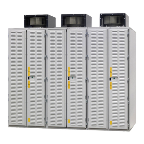
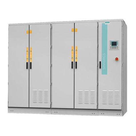
  9. Siemens SINAMICS PERFECT HARMONY GH150 User manual

Siemens SINAMICS PERFECT HARMONY GH150 User manual

Other manuals for SINAMICS PERFECT HARMONY GH150

2

This manual suits for next models

1

Other Siemens DC Drive manuals

Siemens MICROMASTER 430 User manual

Siemens

Siemens MICROMASTER 430 User manual

Siemens SINAMICS V20 Series Instructions for use

Siemens

Siemens SINAMICS V20 Series Instructions for use

Siemens 3VA9 Series User manual

Siemens

Siemens 3VA9 Series User manual

Siemens PXC00-PE96.A User manual

Siemens

Siemens PXC00-PE96.A User manual

Siemens SINAMICS PERFECT HARMONY GH150 Operating instructions

Siemens

Siemens SINAMICS PERFECT HARMONY GH150 Operating instructions

Siemens SINAMICS S120 Parts list manual

Siemens

Siemens SINAMICS S120 Parts list manual

Siemens MICROMASTER 440 User manual

Siemens

Siemens MICROMASTER 440 User manual

Siemens simovert masterdrives User manual

Siemens

Siemens simovert masterdrives User manual

Siemens SED2 VFD Installation manual

Siemens

Siemens SED2 VFD Installation manual

Siemens SINAMICS S120 Quick start guide

Siemens

Siemens SINAMICS S120 Quick start guide

Siemens CP 342-5 User manual

Siemens

Siemens CP 342-5 User manual

Siemens SIMOVERT SLP User manual

Siemens

Siemens SIMOVERT SLP User manual

Siemens SINAMICS S120 Parts list manual

Siemens

Siemens SINAMICS S120 Parts list manual

Siemens SINAMICS S110 Parts list manual

Siemens

Siemens SINAMICS S110 Parts list manual

Siemens SINAMICS G130 User manual

Siemens

Siemens SINAMICS G130 User manual

Siemens SINAMICS G120 CU230P-2 User manual

Siemens

Siemens SINAMICS G120 CU230P-2 User manual

Siemens SINUMERIK 828D Turning User manual

Siemens

Siemens SINUMERIK 828D Turning User manual

Siemens SIMOREG DC-MASTER User manual

Siemens

Siemens SIMOREG DC-MASTER User manual

Siemens SINAMICS S120 Parts list manual

Siemens

Siemens SINAMICS S120 Parts list manual

Siemens SIMOVERT FC User manual

Siemens

Siemens SIMOVERT FC User manual

Siemens SINAMICS GL150 Operating instructions

Siemens

Siemens SINAMICS GL150 Operating instructions

Siemens SINAMICS S120 Parts list manual

Siemens

Siemens SINAMICS S120 Parts list manual

Siemens 3RV1 Series User manual

Siemens

Siemens 3RV1 Series User manual

Siemens 3TL60 User manual

Siemens

Siemens 3TL60 User manual

Popular DC Drive manuals by other brands

National Instruments NI MID-7604 user guide

National Instruments

National Instruments NI MID-7604 user guide

SOMFY Maestria WT Series instructions

SOMFY

SOMFY Maestria WT Series instructions

Danfoss VLT HVAC Design guide

Danfoss

Danfoss VLT HVAC Design guide

Trane TR150 Service manual

Trane

Trane TR150 Service manual

Chamberlain Garog D Series operating manual

Chamberlain Garog

Chamberlain Garog D Series operating manual

Parker PDS Series user guide

Parker

Parker PDS Series user guide

Binks QS-5012-1-CE Service manual

Binks

Binks QS-5012-1-CE Service manual

Danfoss VLT 2800 Series Quick setup

Danfoss

Danfoss VLT 2800 Series Quick setup

YASKAWA CANopen SI-S3 Technical manual

YASKAWA

YASKAWA CANopen SI-S3 Technical manual

GE D20A6 instructions

GE

GE D20A6 instructions

Danfoss VLT AQUA Drive FC 202 operating manual

Danfoss

Danfoss VLT AQUA Drive FC 202 operating manual

Lenze PositionServo 940 user manual

Lenze

Lenze PositionServo 940 user manual

Unex MC-D-250-1000-050W-TW operating manual

Unex

Unex MC-D-250-1000-050W-TW operating manual

Geckodrive G213V manual

Geckodrive

Geckodrive G213V manual

ABB RSYC-01 user manual

ABB

ABB RSYC-01 user manual

Rockwell Automation PowerFlex 700S Programming manual

Rockwell Automation

Rockwell Automation PowerFlex 700S Programming manual

WEG DeviceNet CFW500 user manual

WEG

WEG DeviceNet CFW500 user manual

SOMFY JR RU 30 instructions

SOMFY

SOMFY JR RU 30 instructions

manuals.online logo
manuals.online logoBrands
  • About & Mission
  • Contact us
  • Privacy Policy
  • Terms and Conditions

Copyright 2025 Manuals.Online. All Rights Reserved.

www.siemens.com/drives
Medium-Voltage Drive
SINAMICS PERFECT HARMONY GH150
Type 6SL3825
Operating Instructions
Installation Instructions
Edition 05/2020
19.06.2020 09:58
V14.00
Medium-Voltage Drive
SINAMICS PERFECT HARMONY
GH150
Type 6SL3825
Operating Instructions
Installation Instructions
Edition 05/2020
Introduction 1
Safety instructions 2
Description 3
Preparations for use 4
Assembly 5
Electrical connection 6
Commissioning 7
Operation 8
Maintenance 9
Spare parts 10
Disposal 11
Service & Support A
Technical data and drawings B
Quality documents C
Additional documents D
Legal information
Warning notice system
This manual contains notices you have to observe in order to ensure your personal safety, as well as to prevent
damage to property. The notices referring to your personal safety are highlighted in the manual by a safety alert
symbol, notices referring only to property damage have no safety alert symbol. These notices shown below are
graded according to the degree of danger.
DANGER
indicates that death or severe personal injury will result if proper precautions are not taken.
WARNING
indicates that death or severe personal injury may result if proper precautions are not taken.
CAUTION
indicates that minor personal injury can result if proper precautions are not taken.
NOTICE
indicates that property damage can result if proper precautions are not taken.
If more than one degree of danger is present, the warning notice representing the highest degree of danger will be
used. A notice warning of injury to persons with a safety alert symbol may also include a warning relating to property
damage.
Qualified Personnel
The product/system described in this documentation may be operated only by personnel qualified for the specific
task in accordance with the relevant documentation, in particular its warning notices and safety instructions. Qualified
personnel are those who, based on their training and experience, are capable of identifying risks and avoiding
potential hazards when working with these products/systems.
Proper use of Siemens products
Note the following:
WARNING
Siemens products may only be used for the applications described in the catalog and in the relevant technical
documentation. If products and components from other manufacturers are used, these must be recommended or
approved by Siemens. Proper transport, storage, installation, assembly, commissioning, operation and
maintenance are required to ensure that the products operate safely and without any problems. The permissible
ambient conditions must be complied with. The information in the relevant documentation must be observed.
Trademarks
All names identified by ® are registered trademarks of Siemens AG. The remaining trademarks in this publication
may be trademarks whose use by third parties for their own purposes could violate the rights of the owner.
Disclaimer of Liability
We have reviewed the contents of this publication to ensure consistency with the hardware and software described.
Since variance cannot be precluded entirely, we cannot guarantee full consistency. However, the information in this
publication is reviewed regularly and any necessary corrections are included in subsequent editions.
Siemens AG
Large Drives Applications
Vogelweiherstr. 1-15
90441 NÜRNBERG
GERMANY
Document order number: 6SL3825
Ⓟ 06/2020 Subject to change
Copyright © Siemens AG 2020.
All rights reserved
Table of contents
1 Introduction.................................................................................................................................................13
1.1 About these instructions.........................................................................................................13
2 Safety instructions ......................................................................................................................................15
2.1 Warning symbols on the device .............................................................................................15
2.2 Qualified personnel ................................................................................................................15
2.3 The 5 safety rules...................................................................................................................15
2.4 Safe handling .........................................................................................................................16
2.5 Electromagnetic fields in electrical power engineering installations ......................................18
2.6 Components that can be destroyed by electrostatic discharge (ESD)...................................19
2.7 Information for persons responsible for plants and systems..................................................20
2.7.1 Proper usage..........................................................................................................................20
2.7.2 Grounding concept.................................................................................................................21
2.7.3 Installation site safety.............................................................................................................21
2.7.4 Measures for operator protection in electromagnetic fields ...................................................22
2.7.5 Requirements for the circuit breaker provided by the customer.............................................22
2.8 Residual risks.........................................................................................................................23
2.9 Security information ...............................................................................................................25
3 Description..................................................................................................................................................27
3.1 Area of application .................................................................................................................27
3.2 Safety concept .......................................................................................................................27
3.2.1 Safety components and functions ..........................................................................................27
3.2.2 External safety components...................................................................................................28
3.2.3 Protection and monitoring functions of internal components .................................................28
3.2.4 Protection and monitoring functions for external components ...............................................28
3.3 Design ....................................................................................................................................29
3.4 Control Module.......................................................................................................................30
3.5 Basic Line Module..................................................................................................................30
3.6 Motor Module employing M2C technology.............................................................................30
3.7 Re-cooling unit ......................................................................................................................32
3.7.1 Cooling unit requirements ......................................................................................................32
3.7.2 Operating principle of the re-cooling unit ...............................................................................33
3.7.3 The internal deionized water circuit........................................................................................33
3.7.4 The external raw water circuit ................................................................................................34
3.8 Components...........................................................................................................................35
3.8.1 Control Unit ............................................................................................................................36
3.8.2 Power Stack Adapter .............................................................................................................36
SINAMICS PERFECT HARMONY GH150 6SL3825
Operating Instructions 05/2020 5
3.8.3 Terminal Modules...................................................................................................................38
3.8.4 Power cell...............................................................................................................................38
3.8.4.1 IGBT module ..........................................................................................................................38
3.8.4.2 Capacitor bank .......................................................................................................................39
3.8.5 Door limit switch .....................................................................................................................39
3.8.6 Electromechanical door interlocking system ..........................................................................39
3.8.7 Precharging............................................................................................................................40
3.8.8 Actual value sensing ..............................................................................................................40
3.8.9 Common power supply ..........................................................................................................40
3.8.9.1 Field of application .................................................................................................................40
3.8.9.2 Connections ...........................................................................................................................41
3.8.9.3 Interface description...............................................................................................................41
3.8.10 Touch screen operator panel .................................................................................................42
3.8.11 DC/DC converter....................................................................................................................43
3.8.12 Line filter.................................................................................................................................43
3.8.13 SIRIUS safety relay................................................................................................................43
3.8.14 Auxiliary power supply ...........................................................................................................44
3.8.14.1 1 AC auxiliary voltage ............................................................................................................44
3.8.14.2 3 AC auxiliary voltage supply ................................................................................................44
3.8.15 Customer terminal strips ........................................................................................................44
3.9 Interfaces ...............................................................................................................................45
3.9.1 Hydraulic interfaces................................................................................................................45
3.9.2 Electrical interfaces ................................................................................................................45
3.9.3 DRIVE-CLiQ interface ............................................................................................................46
4 Preparations for use ...................................................................................................................................47
4.1 Requirements for installation location ....................................................................................47
4.2 Inspections when the equipment is received .........................................................................47
4.2.1 Checking shock and tilt indicators..........................................................................................47
4.2.2 Checking the load handling attachments ...............................................................................48
4.3 Transport................................................................................................................................49
4.3.1 Transport markings ................................................................................................................49
4.3.2 Transport requirements..........................................................................................................49
4.3.3 Observe center of gravity .......................................................................................................50
4.3.4 Transport with a fork-lift truck.................................................................................................50
4.3.5 Transport with a crane ...........................................................................................................51
4.3.6 Using lifting rods.....................................................................................................................51
4.3.7 Transporting transportation units packed in boxes ................................................................53
4.3.8 Transporting a re-cooling unit ................................................................................................54
4.4 Unpacking the cabinets..........................................................................................................55
4.4.1 Removing the packaging........................................................................................................55
4.4.2 Removing load securing devices ...........................................................................................55
4.4.3 Lifting the cabinet off the transport pallet ...............................................................................56
4.4.4 Opening doors in preparation for use.....................................................................................56
4.4.5 Checking the shock and tilt indicators inside the cabinet.......................................................57
4.5 Storage...................................................................................................................................57
4.5.1 Emptying the drive .................................................................................................................57
4.5.2 Storing a device .....................................................................................................................58
4.5.3 Storing fans ............................................................................................................................60
4.5.4 Storing re-cooling units ..........................................................................................................60
Table of contents
SINAMICS PERFECT HARMONY GH150 6SL3825
6Operating Instructions 05/2020
5 Assembly ....................................................................................................................................................61
5.1 Safety instructions for assembly ............................................................................................61
5.2 Tools required ........................................................................................................................62
5.3 Screwing the transport units together ....................................................................................63
5.4 Connect to the foundation ......................................................................................................64
5.5 Connecting cabinets...............................................................................................................65
5.5.1 Connecting the interface cable...............................................................................................65
5.6 Connecting the water circuits .................................................................................................66
6 Electrical connection...................................................................................................................................69
6.1 Safety instructions for electrical connections .........................................................................69
6.2 Electromagnetic compatibility.................................................................................................71
6.3 Potential concept....................................................................................................................74
6.4 Cable cross-sections..............................................................................................................74
6.5 Connecting ground.................................................................................................................75
6.6 Laying the signal lines............................................................................................................76
6.7 Connecting the auxiliary voltage ............................................................................................77
6.8 Connecting power cables.......................................................................................................77
6.8.1 Preparations...........................................................................................................................77
6.8.2 Procedure...............................................................................................................................79
6.8.3 Shield connection...................................................................................................................79
6.9 Connecting the re-cooling unit to the drive.............................................................................80
6.10 Interconnecting optional connections.....................................................................................80
6.11 Fastening the cable ducts with cable ties...............................................................................81
7 Commissioning ...........................................................................................................................................83
7.1 Commissioning.......................................................................................................................83
7.2 Safety instructions for commissioning....................................................................................83
7.3 STARTER software................................................................................................................84
8 Operation....................................................................................................................................................85
8.1 Safety instructions for operation.............................................................................................85
8.2 Operating the converter .........................................................................................................86
8.3 Functions................................................................................................................................86
8.3.1 Monitoring functions and protective functions ........................................................................86
8.3.1.1 Insulation monitoring ..............................................................................................................87
8.3.1.2 Tripping of the circuit-breaker in case of undervoltage ..........................................................88
8.4 Fault and system messages ..................................................................................................88
8.4.1 Indicating and rectifying faults................................................................................................88
8.4.2 Diagnostics via LEDs .............................................................................................................89
8.4.2.1 LEDs of the Power Stack Adapters........................................................................................89
Table of contents
SINAMICS PERFECT HARMONY GH150 6SL3825
Operating Instructions 05/2020 7

8.4.2.2 LEDs of the Sirius safety relay ...............................................................................................90
9 Maintenance ...............................................................................................................................................91
9.1 Safety instructions for maintenance .......................................................................................91
9.2 Grounding the system ............................................................................................................93
9.2.1 Grounding using the grounding harness ................................................................................93
9.3 Opening the device ................................................................................................................94
9.4 Preventive maintenance.........................................................................................................95
9.4.1 Inspection...............................................................................................................................95
9.4.2 Checklist for preventive maintenance work............................................................................95
9.4.3 Visual inspections ..................................................................................................................96
9.4.3.1 Equipment for visual inspections............................................................................................96
9.4.3.2 Checking the isolating clearances..........................................................................................96
9.4.3.3 Checking hoisting solenoids and security bolts......................................................................97
9.4.3.4 Checking the plug connections. .............................................................................................97
9.4.3.5 Checking the cable and screw terminals................................................................................97
9.4.3.6 Inspecting door limit switches ................................................................................................97
9.4.3.7 Checking the cooling circuit ...................................................................................................97
9.5 Maintenance...........................................................................................................................98
9.5.1 Replacing a fan ......................................................................................................................98
9.5.1.1 Replacing fans, from the front ................................................................................................98
9.5.1.2 Replacing fans, from the back................................................................................................99
9.6 Cleaning ...............................................................................................................................100
9.6.1 Cleaning aluminum parts .....................................................................................................101
9.7 Repair...................................................................................................................................101
9.7.1 Components that can be replaced .......................................................................................103
9.7.2 Torques ................................................................................................................................103
9.7.3 Replacing the AVT combination module ..............................................................................105
9.7.4 Replacing the current transformer........................................................................................106
9.7.5 Replacing the precharging transformer................................................................................107
9.7.6 Replacing the precharging rectifier ......................................................................................108
9.7.7 Replacing a power cell .........................................................................................................109
9.7.8 Replacing a diode stack .......................................................................................................115
9.7.8.1 Discharging the snubber circuit capacitor ............................................................................115
9.7.8.2 Removing .............................................................................................................................116
9.7.8.3 Installing ...............................................................................................................................122
9.7.9 Replacing water sensors......................................................................................................124
9.7.10 Replacing the TP900 operator panel ...................................................................................126
9.7.11 Replacing the CompactFlash card .......................................................................................127
10 Spare parts ...............................................................................................................................................129
11 Disposal....................................................................................................................................................131
11.1 Information according to Article 33 of the REACH regulation ..............................................131
11.2 Disposing of packaging material ..........................................................................................131
11.3 Removing device components and old devices ...................................................................132
Table of contents
SINAMICS PERFECT HARMONY GH150 6SL3825
8Operating Instructions 05/2020
A Service & Support.....................................................................................................................................133
B Technical data and drawings....................................................................................................................135
B.1 Standards and regulations ...................................................................................................135
B.2 Environmental conditions .....................................................................................................136
C Quality documents....................................................................................................................................139
D Additional documents ...............................................................................................................................141
Index.........................................................................................................................................................143
Tables
Table 3-1 Deionized water requirements.....................................................................................................33
Table 3-2 Raw water requirements .............................................................................................................35
Table 3-3 DRIVE-CLiQ interface .................................................................................................................46
Table 6-1 Cable cross-sections...................................................................................................................74
Table 6-2 Cleaning agents and grease .......................................................................................................78
Table 8-1 LEDs of the Power Stack Adapters ............................................................................................89
Table 8-2 LEDs of the Sirius safety relay ...................................................................................................90
Table 9-1 General checklist for preventive maintenance work....................................................................95
Table 9-2 Control Module: Checklist for preventive maintenance work ......................................................96
Table 9-3 Tightening torque for screws.....................................................................................................103
Table 9-4 Tightening torques for screw terminals for copper cables without cable lug 1).........................104
Table B-1 Standards and regulations ........................................................................................................135
Table B-2 Climatic environmental conditions.............................................................................................136
Table B-3 Mechanical ambient conditions .................................................................................................136
Table B-4 Other ambient conditions ..........................................................................................................137
Figures
Figure 2-1 ESD information ..........................................................................................................................19
Figure 3-1 Example – Design of the converter .............................................................................................29
Figure 3-2 Block diagram: Basic Line Module with diodes ...........................................................................30
Figure 3-3 Block diagram: Motor Module employing M2C technology .........................................................31
Figure 3-4 Interface overview of Power Stack Adapter 5 .............................................................................37
Figure 3-5 Power cell....................................................................................................................................38
Figure 3-6 Overview ....................................................................................................................................41
Figure 3-7 Operator panel ...........................................................................................................................42
Figure 3-8 Line filter......................................................................................................................................43
Figure 3-9 Auxiliary supply and signal interfaces .........................................................................................45
Figure 4-1 Example of attaching and displaying the shock and tilt indicators ..............................................48
Table of contents
SINAMICS PERFECT HARMONY GH150 6SL3825
Operating Instructions 05/2020 9
Figure 4-2 Example illustration of centers of gravity.....................................................................................50
Figure 4-3 Lifting bar label............................................................................................................................52
Figure 4-4 Securing the lifting rods...............................................................................................................52
Figure 4-5 Transporting a transportation unit (still in packaging) with a crane .............................................54
Figure 4-6 Example: Label with instructions for opening the doors..............................................................56
Figure 5-1 Screwing the cabinets together...................................................................................................64
Figure 5-2 Connecting the grounding for the cabinet units...........................................................................65
Figure 5-3 Example: Connecting the interface cable....................................................................................66
Figure 5-4 Water piping ................................................................................................................................67
Figure 6-1 Shield connection using a clip.....................................................................................................73
Figure 6-2 Bridging shield gaps....................................................................................................................73
Figure 6-3 Potential concept.........................................................................................................................74
Figure 6-4 Connecting_grounding cable.......................................................................................................75
Figure 6-5 Schematic diagram: Connecting power cables ..........................................................................78
Figure 6-6 Shield connection........................................................................................................................80
Figure 6-7 Schematic diagram: Fastening the cable ties..............................................................................81
Figure 9-1 Schematic diagram: Attaching the grounding spider...................................................................93
Figure 9-2 Replacing fans from the front ......................................................................................................98
Figure 9-3 Schematic diagram: Replacing fans from the back.....................................................................99
Figure 9-4 Example of an AVT combination module ..................................................................................105
Figure 9-5 Replacing the current transformer.............................................................................................106
Figure 9-6 Example diagram: Replacing the pre-charging rectifier ............................................................108
Figure 9-7 Removing a power cell, steps 1 - 7 ...........................................................................................110
Figure 9-8 Removing a power cell, steps 8 - 10 .........................................................................................111
Figure 9-9 Removing a power cell, step 11 ................................................................................................111
Figure 9-10 Removing a power cell, step 12 ................................................................................................112
Figure 9-11 Example diagram: Capacitance of the capacitor bank..............................................................113
Figure 9-12 Removing a door.......................................................................................................................116
Figure 9-13 Example diagram: Removing the spacers.................................................................................116
Figure 9-14 Example diagram: Removing the busbars ................................................................................117
Figure 9-15 Example diagram: Removing the lower busbar package..........................................................118
Figure 9-16 Example diagram: Removing the Makrolon cover.....................................................................118
Figure 9-17 Releasing the water inlets and outlets.......................................................................................119
Figure 9-18 Example diagram: Releasing connections of the capacitor module..........................................120
Figure 9-19 Example diagram: Screws fixing the diode stack......................................................................121
Figure 9-20 Example diagram: Removing capacitor modules......................................................................122
Figure 9-21 Wire jumper capacitor module...................................................................................................122
Figure 9-22 Adjusting the close pin bracket..................................................................................................124
Figure 9-23 Replacing the water sensors.....................................................................................................125
Table of contents
SINAMICS PERFECT HARMONY GH150 6SL3825
10 Operating Instructions 05/2020