manuals.online logo
Brands
  1. Home
  2. •
  3. Brands
  4. •
  5. Siemens
  6. •
  7. Industrial PC
  8. •
  9. Siemens SIMATIC IPC627E User manual

Siemens SIMATIC IPC627E User manual

Quick Install Guide
Brownfield Connectivity Starter Kit
Gerät einbauen
Mounting the device
Gerät anschließen
Connecting the device
Gerät in Betrieb nehmen
Commissioning the device
1
2
3
Produktlieferung: Rückmeldung zur
Qualitätskontrolle
Product Delivery: Feedback on Quality Control
http://www.siemens.com/asis
Technical Support
https://support.industry.siemens
.com/cs/ww/en/sc/4868
Ersatzteil-Services
Spare Parts Services
https://support.industry.siemens
.com/cs/ww/en/sc/2110
Weiterführende Informationen
More information
4
05/2023
A5E52637886-AA
SIMATIC
Industrial PC
SIMATIC IPC627E
Vor Einbau und Inbetriebnahme – Before mounting and commissioning
Gerät anbauen – Mounting the device
Stromversorgung anschließen – Connecting the power supply
Potentialausgleich anschließen – Connecting equipotential bonding
Zulässige Einbaulagen – Valid Mounting positions
1.1
1.2
1.3
2.2
2.1
100-240 VAC
Das Gerät ist für den Betrieb an
geerdeten Stromversorgungsnetzen
vorgesehen (TN-Netze nach VDE 0100
Teil 100 bzw.
IEC 60364-1). Der Betrieb über nicht
geerdete oder über Impedanz geerdete
Netze (IT-Netze) ist nicht erlaubt.
The device is intended for operation on
grounded power supply systems (TN
systems according to VDE 0100, Part 100,
or IEC 60364-1). It is not designed for
operation on ungrounded or impedan-
ce-grounded power networks
(IT networks).
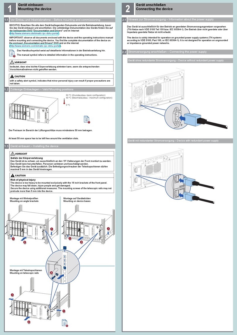
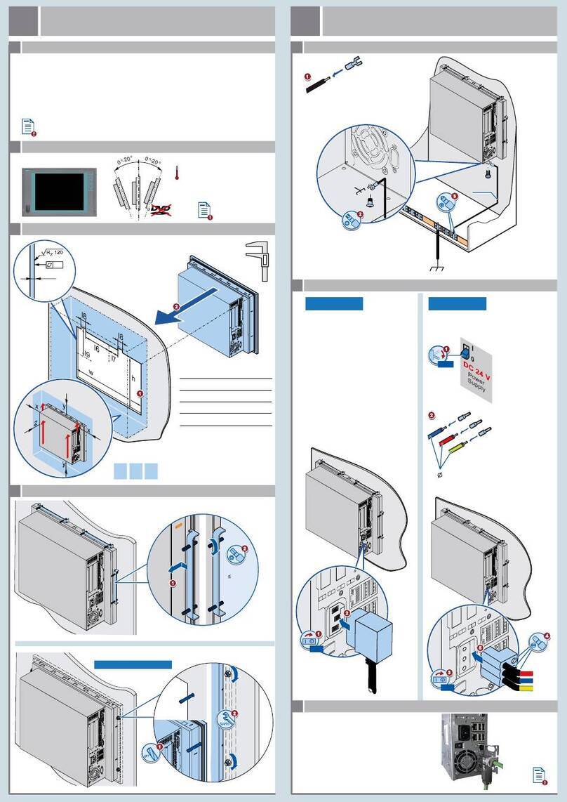
Gerät einbauen
Mounting the device
Gerät anschließen
Connecting the device
1
2
WICHTIG: Beachten Sie alle dem Gerät beiliegenden Dokumente und die Betriebsanleitung, bevor Sie
das Gerät einbauen und anschließen. Die vollständige Dokumentation des Geräts finden Sie auf dem
beiliegenden USB-Stick und im Internet
(http://www.siemens.de/simatic-ipc-doku-portal).
IMPORTANT: observe all documents enclosed with the device and the operating instructions manual
before mounting and connecting the device. You find the complete documentation of the device on
the enclosed USB-Flash drive and on the internet
(http://www.siemens.com/simatic-ipc-doku-portal).
Das Handbuchsymbol weist auf detaillierte Informationen in der Betriebsanleitung hin.
The manual symbol refers to detailed information in the operating instructions.
Stellen Sie sicher, dass die klimatischen Umgebungsbedingungen für die jeweilige Einbaulage
eingehalten werden.
Ensure that the climatic environmental conditions for the specific mounting position are
observed.
Offenes Betriebsmittel - Gehäuse erforderlich
Open Equipment - Enclosure required
2.3 Leitungen sichern – Securing the cables
Sichern Sie die angeschlossenen Leitungen zur
Zugentlastung mit Kabelbindern an den
markierten Befestigungselementen. Achten Sie
darauf, dass die Leitungen durch die Kabelbinder
nicht gequetscht werden. Beispiel:
Use cable ties to secure the connected cables to
the selected fixing elements for strain relief.
Make sure that the cables are not crushed by
the cable tie. Example:
1/ON
3
0/OFF
1
2
1
M4
₂.₅ mm²
Buchmontage (Buchmontagekit; Schnittstellen nach oben/unten)
Book mounting (vertical mounting kit; interfaces up/down)
Buchmontage (Buchmontagekit; Schnittstellen frontseitig)
Book mounting (vertical mounting kit; front interfaces)
Ensure that the mounting surface on the wall can bear four times the total weight
of the device, including fixing elements.
Use only the anchors and screws specified in the operating instructions.
Stellen Sie sicher, dass die Anschraubfläche an der Wand das Vierfache des Gesamtgewichts des
Geräts einschließlich Befestigungselemente tragen kann.
Verwenden Sie nur die in der Betriebsanleitung angegebenen Dübel und Schrauben.
2
T20
5 x M4
T20
7 x M4
T20
2 x M4 T20 6 x M4 T20
2 x M4
T20
2 x M4
T20
Wandmontage (Wandmontageschiene)
Wall mounting (wall monting rail)
3 x M4
T20
T20
3 x M4
3 x M4
T20
T20
3 x M4
15°
15°
20°
20°
Der Freiraum im Bereich der Lüftungsschlitze muss mindestens 100 mm betragen.
0 °C SSD (5 °C HDD)
55 °C (max. load 10 W)
Always maintain a minimum clearance of 100 mm to the area of the ventilation slots.
ec
3.1 Netzwerk und Stromversorgung anschließen
3.2 Gerät einschalten – Switching on the device
3.1 Connecting network and power supply
BFC Installation Wizard 3.3
11
11111111111113
11111111111112
11111111111114
11111111111116
11111111111115
Vergeben Sie ein initiales Passwort.
Assign an initial password.
Konfigurieren Sie das Netzwerk.
Bei Verwendung der Netzwerkschnittstellen X2 P1 oder X3 P1 finden Sie die IP-Adresse in
Kapitel 3.1.
Configure the network.
If you are using the network interfaces X2 P1 or X3 P1, the IP address can be found in
section 3.1.
Konfigurieren Sie den Zeitserver.
Configure the time server.
Optional: Passen Sie die Zeitzone an.
Optional: Adjust the time zone.
Optional: Konfigurieren Sie den Proxyserver.
Optional: Configure the proxy server.
Vergeben Sie die BFC Zugangsdaten.
Assign the BFC access data.
Gerät in Betrieb nehmen
Commissioning the device
3
Schalten Sie den Ein-/Aus-Schalter in Position "1".
Set the on/off switch to position "1".
1
2
Warten Sie ein paar Minuten, bis das System hochgelaufen ist.
Starten Sie auf einem PC im gleichen Netzwerk wie der IPC einen Browser mit der URL
https://<IP oder hostname Ihres IPC>.
Der BFC Installation Wizard wird geöffnet.
Wait for some minutes until the system has started up.
On a PC in the same network as the IPC, launch a web browser with the URL
https://<IP or hostname of your IPC>.
The BFC Installation Wizard is opened.
Press Esc for Boot Options
Stellen Sie bei Geräten, die ohne Pufferbatterie geliefert wurden, sicher, dass vor dem ersten
Einschalten eine Pufferbatterie eingebaut wurde (Artikelnummer A5E00047601).
For devices supplied without a backup battery, make sure that a backup battery is installed before
powering on for the first time (part number A5E00047601).
Die Netzwerkschnittstellen X1 P1 bis X3 P1 sind folgendermaßen vorkonfiguriert:
X1 P1: DHCP, dynamische Vergabe einer IP-Adresse aus Ihrem Netzwerk
X2 P1: 172.16.1.100, statisch, Subnetz 255.255.0.0, Klasse B Netz
X3 P1: 192.168.1.100, statisch, Subnetz 255.255.255.0, Klasse C Netz
Benutzen Sie die Netzwerkschnittstelle, die Ihrer Netzwerkinfrastruktur entspricht.
Network interfaces X1 P1 to X3 P1 are preconfigured as follows:
X1 P1: DHCP, dynamic assignment of an IP address from your network
X2 P1: 172.16.1.100, static, subnet 255.255.0.0, Class B network
X3 P1: 192.168.1.100, static, subnet 255.255.255.0, Class C network
Use the network interface that corresponds to your network infrastructure.
X1 P1 X2 P1 X3 P1 power
supply
11111111111117
11111111111118
9
Weiterführende Informationen
More information
4
Konfigurieren Sie bis zu 3 Steuerungen.
Configure up to 3 controllers.
Um weniger als 3 Steuerungen zu konfigurieren, wählen Sie bei den übrigen im Feld
"Device type“ "None“ aus.
To configure less than 3 controllers, select "None“ in the other "Device type“ fields.
Akzeptieren Sie die Lizenzbedingungen.
Starten Sie die BFC-Gateway Installation.
Accept the conditions in the license agreement.
Start the BFC Gateway installation.
Nach Abschluss der Installation des BFC-Gateway kann die Anwendung direkt gestartet werden.
Sie können die BFC Konfigurationsoberfläche auch über folgende URL in Ihrem Netzwerk öffnen:
"https://<IP oder hostname Ihres IPC>:9877".
Nach erfolgreicher Anmeldung an der BFC Konfigurationsoberfläche haben Sie Zugriff auf
die Brownfield Analytics App zur Visualisierung von Steuerungsdaten.
After completion of the BFC Gateway installation the application can be started right away.
You can also open the BFC configuration interface in your network via following URL:
"https://<IP or hostname of your IPC>:9877".
After successful login to the BFC configuration interface, you have access to the
Brownfield Analytics App for visualizing the control data.
Weiterführende Informationen finden Sie:
- über den QR Code auf dem Typenschild des Geräts
- im BFC Funktionshandbuch
You can find more information:
- via the QR code on the nameplate of the device
- in the BFC function manual
Sie erreichen die BFC-Gateway Dokumentation auch offline:
- über das Info-Icon des BFC Installation Wizard (BFC Gateway function manual)
- über das Info-Icon der BFC Konfigurationsoberfläche Ihres installierten BFC-Gateway
(BFC Gateway Documentation)
You can also access the BFC Gateway documentation offline:
- via the info icon of the BFC Installation Wizard (BFC Gateway funcion manual)
- via the info icon of the BFC configuration interface of your installed BFC Gateway
(BFC Gateway Documentation)
Hotline kontaktieren
Um Kontakt zur Hotline aufzunehmen, nutzen Sie den Service-Request der Seite
https://sieportal.siemens.com/de-de/home.
Contacting the hotline
To contact the hotline, click on the "Support Request" Quick Link on this page:
https://sieportal.siemens.com/en-en/home.
Haftungsausschluss
Wir haben den Inhalt der Druckschrift auf Übereinstimmung mit der beschriebenen Hard- und
Software geprüft. Dennoch können Abweichungen nicht ausgeschlossen werden, so dass wir für die
vollständige Übereinstimmung keine Gewähr übernehmen. Die Angaben in dieser Druckschrift
werden regelmäßig überprüft, notwendige Korrekturen sind in den nachfolgenden Auflagen
enthalten.
Disclaimer of Liability
We have reviewed the contents of this publication to ensure consistency with the hardware and
software described. Since variance cannot be precluded entirely, we cannot guarantee full consisten-
cy. However, the information in this publication is reviewed regularly and any necessary corrections
are included in subsequent editions.
Siemens AG
Industry Sector
Postfach 48 48
90026 NÜRNBERG
Abbildungen
Das vorliegende Dokument enthält Abbildungen zu den beschriebenen Geräten und Zubehör.
Die Abbildungen können bezogen auf das gelieferte Gerät und Zubehör in Einzelheiten abweichen.
Illustrations
This document contains illustrations of the described devices and accessories.
The illustrations may deviate from the particularities of the delivered device and accessories.

Other manuals for SIMATIC IPC627E

2

Other Siemens Industrial PC manuals

Siemens Simatic series User manual

Siemens

Siemens Simatic series User manual

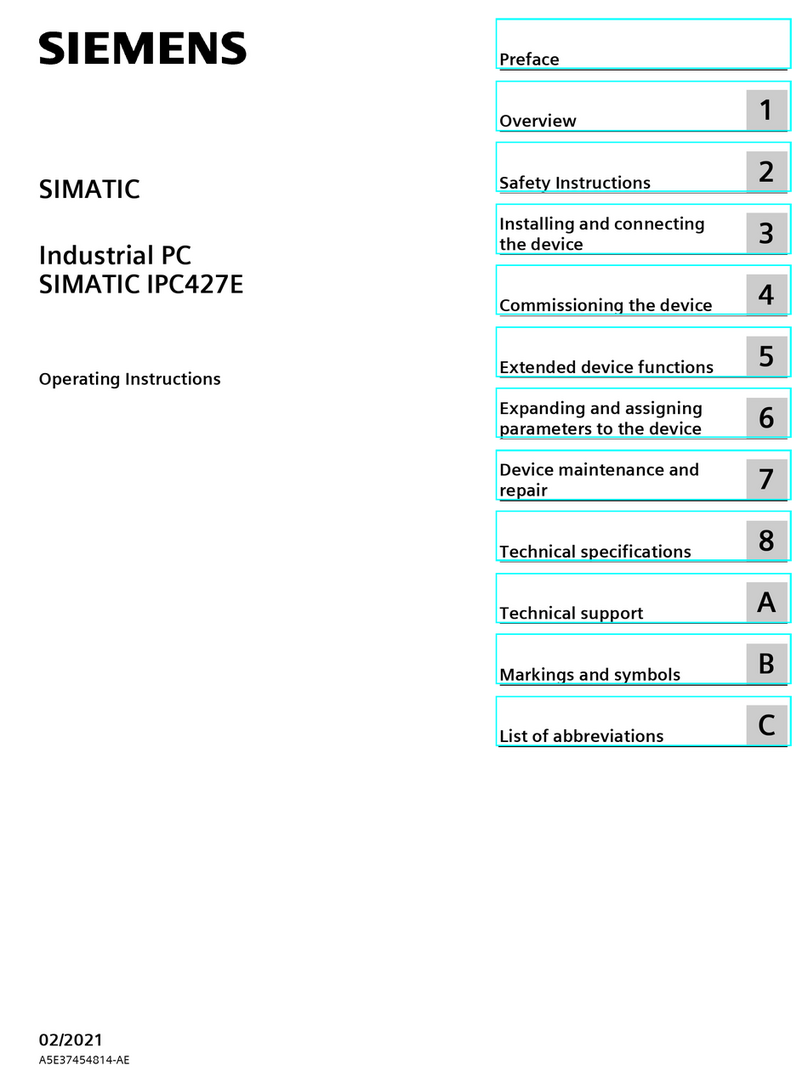
Siemens SIMATIC IPC427E User manual

Siemens

Siemens SIMATIC IPC427E User manual

Siemens SIMATIC IPC347G User manual

Siemens

Siemens SIMATIC IPC347G User manual

Siemens Simatic IPC547G User manual

Siemens

Siemens Simatic IPC547G User manual

Siemens SIMATIC IPC227G User manual

Siemens

Siemens SIMATIC IPC227G User manual

Siemens SIMATIC 427B-RTX User manual

Siemens

Siemens SIMATIC 427B-RTX User manual

Siemens SIMATIC IPC427E User manual

Siemens

Siemens SIMATIC IPC427E User manual

Siemens SIMATIC IPC547E User manual

Siemens

Siemens SIMATIC IPC547E User manual

Siemens SIMATIC IPC377E User manual

Siemens

Siemens SIMATIC IPC377E User manual

Siemens SIMATIC IL43 User manual

Siemens

Siemens SIMATIC IL43 User manual

Siemens SIMATIC IPC477E User manual

Siemens

Siemens SIMATIC IPC477E User manual

Siemens SIMATIC IPC3000 SMART User manual

Siemens

Siemens SIMATIC IPC3000 SMART User manual

Siemens SIMATIC IPC PX-32A User manual

Siemens

Siemens SIMATIC IPC PX-32A User manual

Siemens SIMATIC PANEL PC 877 User manual

Siemens

Siemens SIMATIC PANEL PC 877 User manual

Siemens Simatic series User manual

Siemens

Siemens Simatic series User manual

Siemens Simatic IPC647C User manual

Siemens

Siemens Simatic IPC647C User manual

Siemens SIMATIC IPC1047 User manual

Siemens

Siemens SIMATIC IPC1047 User manual

Siemens SIMATIC IPC BX-32A User manual

Siemens

Siemens SIMATIC IPC BX-32A User manual

Siemens SIMATIC IPC477E User manual

Siemens

Siemens SIMATIC IPC477E User manual

Siemens SIMATIC IPC847C User manual

Siemens

Siemens SIMATIC IPC847C User manual

Siemens SIMATIC IPC477D User manual

Siemens

Siemens SIMATIC IPC477D User manual

Siemens SIMATIC Box PC 840 User manual

Siemens

Siemens SIMATIC Box PC 840 User manual

Siemens SIMATIC 6AV7675-1RB00-0AA0 User manual

Siemens

Siemens SIMATIC 6AV7675-1RB00-0AA0 User manual

Siemens SIMATIC IPC1047E User manual

Siemens

Siemens SIMATIC IPC1047E User manual

Popular Industrial PC manuals by other brands

Premio RCO-1000-EHL Series user manual

Premio

Premio RCO-1000-EHL Series user manual

Omron Sysmac NYB-0 Series Hardware user manual

Omron

Omron Sysmac NYB-0 Series Hardware user manual

Neousys Technology Nuvo-10108GC Series user manual

Neousys Technology

Neousys Technology Nuvo-10108GC Series user manual

Moxa Technologies V2616A Series Quick installation guide

Moxa Technologies

Moxa Technologies V2616A Series Quick installation guide

Chipsee PPC-A55-101 manual

Chipsee

Chipsee PPC-A55-101 manual

IBM 7090 Instruction-Reference

IBM

IBM 7090 Instruction-Reference

MiTWell KUBE-5000 Series user manual

MiTWell

MiTWell KUBE-5000 Series user manual

Quanmax KPC-1561 user guide

Quanmax

Quanmax KPC-1561 user guide

Avalue Technology EMS-SKLU Quick reference guide

Avalue Technology

Avalue Technology EMS-SKLU Quick reference guide

Onlogic IGN100 manual

Onlogic

Onlogic IGN100 manual

Spectra PowerBox 5000C Series user manual

Spectra

Spectra PowerBox 5000C Series user manual

MSI MS-9A78B1 manual

MSI

MSI MS-9A78B1 manual

Rockwell Automation Allen-Bradley 750R user manual

Rockwell Automation

Rockwell Automation Allen-Bradley 750R user manual

Chipsee PPC-A55-050 manual

Chipsee

Chipsee PPC-A55-050 manual

IEI Technology ECW-281B-R21/N270 ECW-281B2-R21/N270 user manual

IEI Technology

IEI Technology ECW-281B-R21/N270 ECW-281B2-R21/N270 user manual

ESA AUTOMATION EW400 manual

ESA AUTOMATION

ESA AUTOMATION EW400 manual

Lanner LEC-7230 user manual

Lanner

Lanner LEC-7230 user manual

Brüel & Kjaer Vibro VIBRO Condition Monitoring 3 Hardware installation instructions

Brüel & Kjaer Vibro

Brüel & Kjaer Vibro VIBRO Condition Monitoring 3 Hardware installation instructions

manuals.online logo
manuals.online logoBrands
  • About & Mission
  • Contact us
  • Privacy Policy
  • Terms and Conditions

Copyright 2025 Manuals.Online. All Rights Reserved.