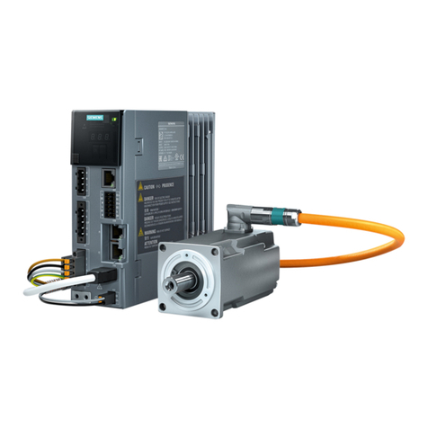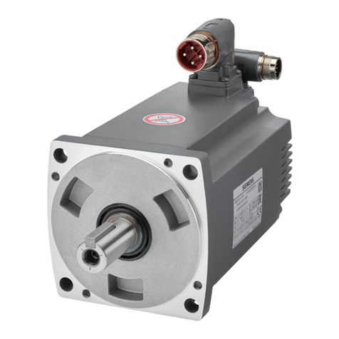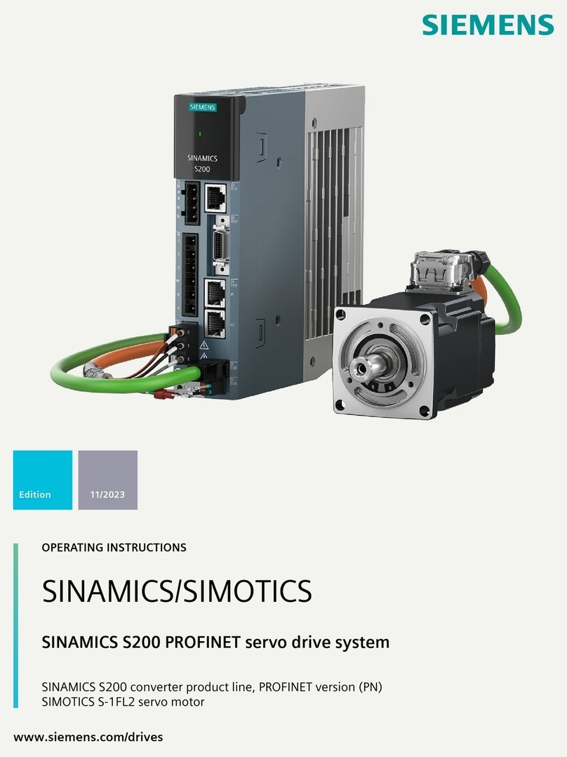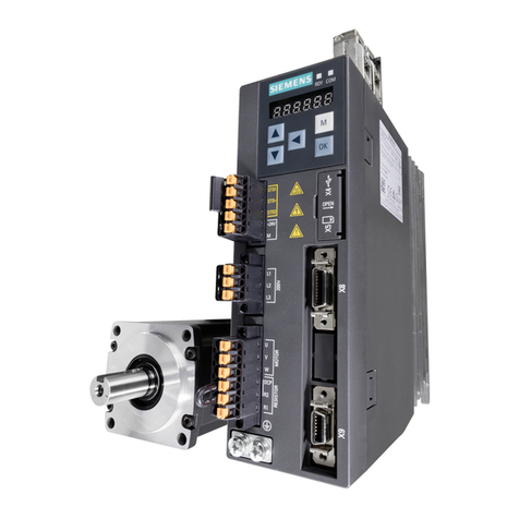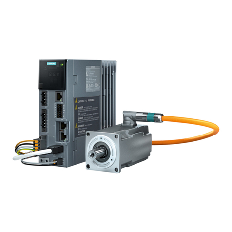
SINAMICS S200 PROFINET servo drive system with SIMOTICS S-1FL2
2A5E52388930A AA, 07/2023
Table of contents
1 Safety notes.................................................................................................................................................................. 3
2 Technical data .............................................................................................................................................................. 3
2.1 Technical data of the converter ............................................................................................................... 3
2.1.1 Permissible climatic conditions for the converter..................................................................................... 3
2.1.2 Specific technical data of the 200 V converter......................................................................................... 4
2.1.3 Specific technical data of the 400 V converter......................................................................................... 4
2.2 Technical data of the 1FL2 motor ............................................................................................................ 5
2.3 Technical data of the MOTION-CONNECT cables...................................................................................... 5
3 Mounting ...................................................................................................................................................................... 6
3.1 Mounting the converter........................................................................................................................... 6
3.1.1 Mounting conditions ............................................................................................................................... 6
3.1.2 Dimension drawings and drill dimensions ............................................................................................... 6
3.1.3 Minimum clearance................................................................................................................................. 7
3.2 Mounting the motor................................................................................................................................ 8
3.2.1 Mounting instructions for the motor ....................................................................................................... 8
3.2.2 Lifting the motor ..................................................................................................................................... 9
3.2.3 Non-thermally insulated mounting.......................................................................................................... 9
3.2.4 Mounting the feather key......................................................................................................................10
3.2.5 Attaching output elements....................................................................................................................10
3.2.6 Lubricating the shaft sealing ring...........................................................................................................12
3.2.7 Routing cables in damp environments...................................................................................................12
4 Connecting .................................................................................................................................................................12
4.1 System overview....................................................................................................................................13
4.2 Overview of the converter interfaces.....................................................................................................15
4.3 MOTION-CONNECT cables .....................................................................................................................16
4.4 System connection ................................................................................................................................17
4.4.1 Conductor cross-sections and cable lugs................................................................................................17
4.4.2 Connecting the mains supply and braking resistor - X1 .........................................................................17
4.4.3 Connecting the motor power - X2 .........................................................................................................18
4.4.4 Connecting the motor holding brake - X108..........................................................................................19
4.4.5 Connecting the encoder - X120 .............................................................................................................20
4.4.6 Connecting the 24 V DC power supply - X124 ....................................................................................... 21
4.4.7 Connecting the service interface - X127 ................................................................................................21
4.4.8 Connecting the inputs and outputs - X130 ............................................................................................21
4.4.9 Connecting STO - X131 (for the S200 converter only) ........................................................................... 21
4.4.10 Connecting to the fieldbus - X150 .........................................................................................................22
4.5 Block diagram........................................................................................................................................22
5 Commissioning with web server ...............................................................................................................................23
5.1 Supported hardware and software ........................................................................................................23
5.2 Preparing for commissioning.................................................................................................................23
5.3 Configuring the fundamental settings...................................................................................................24
5.4 Structure of the web server ...................................................................................................................25
5.5 Performing quick setup.......................................................................................................................... 27
5.6 Performing One Button Tuning..............................................................................................................29
6 Diagnostics and monitoring....................................................................................................................................... 30
6.1 Diagnostics and monitoring with SINAMICS SDI Status.......................................................................... 30
6.2 Fault causes and remedial measures for the motor................................................................................ 31
7 Additional information .............................................................................................................................................. 32
