Siko IG09M Operation manual

IG09M Datum 02.08.2007 Art.Nr. 81827 Änd. Stand 197/07 1
A vor B
DEUTSCH
1. Gewährleistungshinweise
Lesen Sie vor der Montage und der Inbetriebnahme
dieses Dokument sorgfältig durch. Beachten Sie zu
Ihrer eigenen Sicherheit und der Betriebssicherheit
alle Warnungen und Hinweise.
Ihr Produkt hat unser Werk in geprüftem und be-
triebsbereitem Zustand verlassen. Für den Betrieb
gelten die angegeben Spezifikationen und die
Angaben auf dem Typenschild als Bedingung.
Garantieansprüche gelten nur für Produkte der
Firma SIKO GmbH. Bei dem Einsatz in Verbindung
mit Fremdprodukten besteht für das Gesamtsystem
kein Garantieanspruch.
Reparaturen dürfen nur im Werk vorgenommen
werden. Für weitere Fragen steht Ihnen die Firma
SIKO GmbH gerne zur Verfügung.
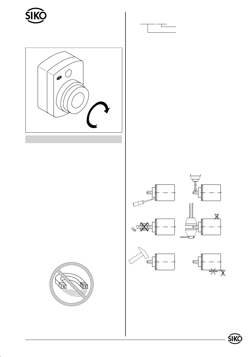
Fremdmagnete fernhalten.
•
•
•
•
•
z.B. IG09M-0023
Varianten-Nr.
Geräte-Typ
3. Montagehinweise
Gehen Sie sorgfältig mit dem Geber um. Es handelt
sich um ein Präzisionsmessgerät. Folgende Punkte
führen unverzüglich zum Verfall der Garantie:
Zerlegen oder Öffnen des Gebers (soweit dies
nicht in dieser Benutzerinformation beschrieben
wird).
Unsachgemäße Kupplung der Geberwelle z.B. mit
steifen Kupplungen, die zu große Kräfte auf die
Lagerung der Geberwelle erzeugen.
Schläge auf das Gehäuse und die Welle beschä-
digen den Geber bzw. innere Teile und sind nicht
zulässig.
Mechanische Bearbeitung der Welle, des Flansches
oder Gehäuses (Bohren, Fräsen, usw.). Hierdurch
kann es zu schweren Beschädigungen der inneren
Teile des Gebers kommen.
Unzulässige axiale oder radiale Belastung der
Welle.
Unsachgemäße Befestigung des Gebers.
Was Sie nicht tun sollten
•
•
•
•
•
•
Benutzerinformation
IG09M
Inkrementalgeber
2. Identifikation
Das Typenschild zeigt den Gerätetyp mit Varianten-
nummer. Die Lieferpapiere ordnen jeder Varianten-
nummer eine detaillierte Bestellbezeichnung zu.
4. Mechanische Montage
Die Montage darf nur gemäß der angegebenen IP-
Schutzart vorgenommen werden. Das System muss
ggf. zusätzlich gegen schädliche Umwelteinflüsse,
wie z.B. Spritzwasser, Staub, Schläge, Temperatur
geschützt werden.
Nach dem Aufschieben des IG09M auf die Vollwelle
und dem Einführen der Drehmomentstütze in die
vorbereitete Bohrung, wird durch den Gewindestift

2 IG09M Datum 02.08.2007 Art.Nr. 81827 Änd. Stand 197/07
Abb. 1: Montagehinweise
Drehmomentabstützung Form A: Stift-ø 6 h9
Form B: Bohr-ø 10 +0.8
die Gerätehohlwelle mit der Maschinenvollwelle
verbunden (siehe Abb.1).
Zwischen Welle und IG09M ist ein Schiebesitz
vorzusehen.
Achten Sie auf geringen Wellen- bzw. Winkelver-
satz. Verspannungen sind zu vermeiden und die
maximalen axialen und radialen Wellenbelas-
tungen zu beachten. Verspannungen führen zu
erhöhter Lagerbelastung, unzulässiger Erwärmung
und kürzerer Lebensdauer des Lagers.
Insbesondere bei Verwendung der Drehmoment-
abstützung Form A ist darauf zu achten dass das
Gerät bei der Montage nicht durch Verkanten
verspannt montiert wird. Dies ist bei der Wahl
des Bohr- ø zu beachten.
•
•
•
rung und Verdrahtung können Störeinflüsse (z.B.
von Schaltnetzteilen, Motoren, getakteten Reg-
lern oder Schützen) vermindert werden.
Insbesondere bei der Ausführung mit der Betriebs-
spannung +5V darf die untere Toleranzgrenze
nicht unterschritten werden, da ansonsten die
einwandfreie Funktion des Gebers nicht mehr ge-
währleistet werden kann! Bei Anschlussart E1 und
Verwendung von langen Anschlussleitungen (>3m)
sowie 5V-Betrieb muss immer sichergestellt sein,
dass am Geber die Betriebsspannung innerhalb
der Toleranz ist! (Sichere Lösung: Kabelenden des
Gebers mit 10-poligem Kabel weiterführen; +UB
und GND jeweils mit einer Senseleitung verbin-
den.)
Erforderliche Maßnahmen
Nur geschirmtes Kabel verwenden. Den Kabel-
schirm beidseitig auflegen. Litzenquerschnitt der
Leitungen min. 0,14mm², max. 0,5mm².
Die Verdrahtung von Abschirmung und Masse
(0V) muss sternförmig und großflächig erfolgen.
Der Anschluss der Abschirmung an den Potenti-
alausgleich muss großflächig (niederimpedant)
erfolgen.
Das System muss in möglichst großem Abstand von
Leitungen eingebaut werden, die mit Störungen
belastet sind; ggfs. sind zusätzliche Maßnahmen
wie Schirmbleche oder metallisierte Gehäuse
vorzusehen. Leitungsführungen parallel zu Ener-
gieleitungen vermeiden.
Schützspulen müssen mit Funkenlöschgliedern
beschaltet sein.
Spannungsversorgung
Die Spannungswerte sind abhängig von der Ge-
räteausführung und sind den Lieferpapieren oder
dem Typenschild zu entnehmen.
10 ... 30 VDC, verpolungsfest
5 VDC±5% nicht verpolungsfest
5.1 Anschlussart E1
Anschlussbelegung PP
Farbe Belegung
grau GND
gelb Kanal A
weiß Kanal B
grün Kanal 0/I
braun +UB
schwarz Schirm
•
•
•
•
Bei Verwendung der Zwischenplatte (Option)
wird zuerst diese in oben beschriebener Weise be-
festigt und danach der IG09M montiert.
5. Elektrischer Anschluss
Anschlussverbindungen dürfen nicht unter
Spannung geschlossen oder gelöst werden!!
Verdrahtungsarbeiten dürfen nur spannungslos
erfolgen.
Litzen sind mit Aderendhülsen zu versehen.
Vor dem Einschalten sind alle Leitungsanschlüsse
und Steckverbindungen zu überprüfen.
Hinweise zur Störsicherheit
Alle Anschlüsse sind gegen äußere Störeinflüsse
geschützt. Der Einsatzort ist aber so zu wählen,
dass induktive oder kapazitive Störungen nicht
auf den Geber oder deren Anschlussleitungen
einwirken können! Durch geeignete Kabelfüh-
•
•
•
•

IG09M Datum 02.08.2007 Art.Nr. 81827 Änd. Stand 197/07 3
1)
Ansichtseite =
Steckseite
Ansichtseite =
Steckseite
Ansichtseite =
Steckseite
Ansichtseite =
Steckseite
Anschlussbelegung OP, LD24, LD5
Farbe Belegung
gelb Kanal A
rosa Kanal /A
weiß Kanal B
blau Kanal /B
grün Kanal 0
rot Kanal I
braun +UB
grau GND
5.2 Anschlussart E6X
Anschlussbelegung PP 12-pol. Stiftkontakt
Pin Belegung
A - - -
B - - -
C Kanal 0/I
D - - -
E Kanal A
F - - -
G - - -
H Kanal B
J - - -
K GND
L - - -
M +UB
Anschlussbelegung OP, LD24 12-pol. Stiftkontakt
Pin Belegung
A Kanal /B
B - - -
C Kanal 0
D Kanal I
E Kanal A
F Kanal /A
G - - -
H Kanal B
J - - -
K GND
L - - -
M +UB
Anschlussbelegung LD5 12-pol. Stiftkontakt
Pin Belegung
A Kanal /B
B +SUB (Sensor)
C Kanal 0
D Kanal I
E Kanal A
F Kanal /A
G - - -
H Kanal B
J - - -
K GND
L SGND (Sensor)
M +UB
* intern verbunden
5.3 Anschlussart E7X
Anschlussbelegung PP 6-pol. Stiftkontakt
Pin Belegung
1 GND
2 +UB
3 Kanal A
4 Kanal B
5 Kanal 0/I
6 - - -
6. Ausgangssignale
PP
OP, LD5
Achtung! Die Verpolschutzdiode (1) entfällt bei
Versionen mit UB = +5VDC±5%.
LD24
*
}*

4 IG09M Datum 02.08.2007 Art.Nr. 81827 Änd. Stand 197/07
Abb. 2: Phasenlage
Abb. 3: Signalbild Komplementär
6.1 Ausgangssignale/ Impulsbild
IG09M Datum 02.08.2007 Art.Nr. 81827 Änd. Stand 197/07 5
A before B
ENGLISH
1. Warranty information
In order to carry out installation correctly, we
strongly recommend this document is read very
carefully. This will ensure your own safety and
the operating reliability of the device.
Your device has been quality controlled, tested
and is ready for use. Please observe all warnings
and information which are marked either directly
on the device or specified in this document.
Warranty can only be claimed for components
supplied by SIKO GmbH. If the system is used
together with other products, there is no warranty
for the complete system.
Repairs should be carried out only at our works.
If any information is missing or unclear, please
contact the SIKO sales staff.
Keep away foreign magnets.
•
•
•
•
•
delivery documentation.
e.g. IG09M-0023
version number
type of unit
3. Mounting instructions
Please handle the encoder carefully as it is a high-
precision device.
Especially do not:
disassemble or open the encoder (unless stipulated
in this brochure).
link encoder's shaft with rigid couplings as this
would expose the encoder's shaft bearing to
high forces.
knock the housing and the shaft, because this will
damage the encoder or internal parts.
machine (bore, mill ...) flange or shaft. This could
lead to severe damage inside the encoder.
exceed the values for the maximum axial and
radial shaft load.
mount the encoder incorrectly.
Otherwise manufacturer's warranty will be invalida-
ted!
Never...
•
•
•
•
•
•
User Information
IG09M
Incremental encoder
2. Identification
Please check the particular type of unit and type
number from the identification plate. Type number
and the corresponding version are indicated in the
4. Installation
For mounting, the degree of protection specified
must be observed. If necessary, protect the unit
against environmental influences such as sprayed
water, dust, knocks, extreme temperatures.
Slide IG09M onto the solid shaft, insert torque
pin into the prebored mounting hole and use
grub screw to fix the IG09M's hollow shaft to the
machine's solid shaft (see fig. 1).

6 IG09M Datum 02.08.2007 Art.Nr. 81827 Änd. Stand 197/07
Fig. 1: Mounting instructions
Torque pin type A: pin ø 6 h9
type B: bore ø 10 +0.8
Ensure sliding fit between solid shaft and
IG09M.
Ensure accurate shaft alignment and mount the
IG09M without force. Do not exceed the values
for the maximum axial and radial shaft load. If
the shaft is not correctly aligned, strain on the
bearings will result, which may cause overheating
and irreparable damage.
Especially when using torque pin type A for fixing,
ensure that IG09M does not jam and that it is
mounted without strain. Please remember this
when choosing the IG09M's bore diameter.
•
•
•
below the tolerance limit or the encoder will not
function correctly! At connection type E1 and in
case of long connection lines (>3m) as soon as 5V
operating voltage it must always be guaranteed
that the encoder's operating supply is within the
defined tolerances! (Safe solution: use 10-pole
cable to extend encoder's cable head; connect
+UB and GND respectively with one sense line.)
Necessary measures
Only screened cable should be used. Screen
should be connected to earth at both ends.
Wire cross section is to be at least 0,14mm²,
max. 0,5mm².
Wiring to screen and to ground (0V) must be via
a good earth point having a large surface area
for minimum impedance.
The unit should be positioned well away from
cables with interference; if necessary a protective
screen or metal housing must be provided. The
running of wiring parallel to the mains supply
should be avoided.
Contactor coils must be linked with spark sup-
pression.
Power supply
Operating voltage depends on execution and is
indicated in the delivery documentation or on the
identification plate.
10 ... 30 V d.c., with polarity protection
5 V d.c. ±5% without polarity protection
5.1 Connection type E1
Pin connection PP
Color Designation
grey GND
yellow channel A
white channel B
green channel 0/I
brown +UB
black screening
Pin connection OP, LD24, LD5
Color Designation
yellow channel A
pink channel /A
white channel B
blue channel /B
green channel 0
red channel I
brown +UB
grey GND
•
•
•
•
When used in combinaton with an intermediate
plate (option) the plate should be mounted first
and only afterwards the encoder IG09M.
5. Electrical connection
Switch power off before any plug is inserted
or removed!!
Wiring must only be carried out with power off.
Provide standed wires with ferrules.
Check all lines and connections before switching
on the equipment.
Interference and distortion
All connections are protected against the effects
of interference. The location should be selected
to ensure that no capacitive or inductive in-
terferences can affect the encoder or the con-
nection lines! Suitable wiring layout and choice
of cable can minimise the effects of interference
(eg. interference caused by SMPS, motors, cyclic
controls and contactors).
When using encoders with operating voltage +5V
ensure that the operating voltage does not fall
•
•
•
•

IG09M Datum 02.08.2007 Art.Nr. 81827 Änd. Stand 197/07 7
viewing side =
plug-in side
viewing side =
plug-in side
viewing side =
plug-in side
viewing side =
plug-in side
1)
Fig. 2: Phase relation
Fig. 3: Signal shape inverted
5.2 Connection type E6X
Pin connection PP 12 pole plug pin
Pin Designation
A - - -
B - - -
C channel 0/I
D - - -
E channel A
F - - -
G - - -
H channel B
J - - -
K GND
L - - -
M +UB
Pin connection OP, LD24 12 pole plug pin
Pin Designation
A channel /B
B - - -
C channel 0
D channel I
E channel A
F channel /A
G - - -
H channel B
J - - -
K GND
L - - -
M +UB
Pin connection LD5 12 pole plug pin
Pin Designation
A channel /B
B +SUB (sensor)
C channel 0
D channel I
E channel A
F channel /A
G - - -
H channel B
J - - -
K GND
L SGND (sensor)
M +UB
* internally linked
5.3 Connection type E7X
Pin connection PP 6 pole plug pin
Pin Designation
1 GND
2 +UB
3 channel A
4 channel B
5 channel 0/I
6 - - -
6. Output signals
PP
OP, LD5
Atttention! Encoders with UB = +5VDC ±5% are
without reversal protection diode.
LD24
6.1 Output signals/ Wave form
*
}*

8 IG09M Datum 02.08.2007 Art.Nr. 81827 Änd. Stand 197/07
SIKO GmbH
Werk / Factory:
Weihermattenweg 2
79256 Buchenbach-Unteribental
Postanschrift / Postal address:
Postfach 1106
79195 Kirchzarten
Telefon/Phone +49 7661 394-0
Telefax/Fax +49 7661 394-388
E-Mail info@siko.de
Internet www.siko.de
Service [email protected]e
This manual suits for next models
1
Table of contents
Languages:
Other Siko Media Converter manuals


