Siko IH5815 User manual
Kurzanleitung
IH5815 · Datum 27.09.2022 · Art. Nr. 89300 · Änd. Stand 194/22
SIKO GmbH
Weihermattenweg 2
79256 Buchenbach
www.siko-global.com
Telefon: + 49 7661 394-0
Telefax: + 49 7661 394-388
Service: suppor[email protected]
IH5815
Inkrementalgeber
Ausführlichere Dokumentationen unter
http://www.siko-global.com/p/ih5815
Allgemeine Hinweise
Vor der Installation, einschließlich in Gefahrenbereichen, lesen Sie die Monta-
geanleitung (Download Internet). Sie enthält die Sicherheitsvorschriften, Hin-
weise und technischen Daten, die bei der Installation zu beachten sind. Ände-
rungen sind vorbehalten.
Vorsicht
Damit dieses Produkt zuverlässig funktioniert, muss es sachgemäß transpor-
tiert, aufbewahrt, positioniert und montiert werden. Es muss mit Sorgfalt
betrieben und gewartet werden. Nur entsprechend qualifiziertes Personal darf
dieses Produkt installieren und betreiben.
Sicherheitshinweise
Aus Sicherheitsgründen ist es wichtig, dass Sie die folgenden Punkte lesen und
verstehen, bevor Sie das System installieren:
• Installation, Anschluss, Inbetriebnahme und Wartung ist von Personal aus-
zuführen, das entsprechend qualifiziert ist.
• Es liegt in der Verantwortung des Kunden, dass das betreende Personal vor
der Installation des Gerätes die Anweisungen und Richtungsangaben in die-
ser Anleitung und in der Montageanleitung versteht und befolgt.
• Es liegt in der Verantwortung des Kunden, sicherzustellen, dass der Inkre-
mentalgeber richtig angeschlossen und konfiguriert ist.
• Reparatur und Wartung ist nur von Personal durchzuführen, das von SIKO
besonders geschult wurde.
Mechanische Montage
Die Montage darf nur gemäß der angegebenen IP-Schutzart vorgenommen wer-
den. Das Gerät muss ggfs. zusätzlich gegen schädliche Umwelteinflüsse, wie z.
B. Spritzwasser, Staub, Schläge, Temperatur geschützt werden.
Achtung!
Radialdichtringe sind Verschleißteile! Die Schutzart ist deshalb abhängig von
Lebensdauer und Zustand der Dichtringe.
Montagehinweise
Gehen Sie sorgfältig mit dem Geber um. Es handelt sich um ein Präzisionsmess-
gerät. Folgende Punkte führen unverzüglich zum Verfall der Garantie:
• Zerlegen oder Önen des Gebers.
• Unsachgemäße Kupplung der Geberwelle z. B. mit steifen Kupplungen, die
zu große Kräfte auf die Lagerung der Geberwelle erzeugen.
• Schläge auf den Geber oder die Welle, da dadurch interne Elemente beschä-
digt werden können.
• Mechanische Bearbeitung der Welle, des Flansches oder Gehäuses (Bohren,
Fräsen, usw.). Hierdurch kann es zu schweren Beschädigungen der inneren
Teile des Gebers kommen.
• Unzulässige axiale oder radiale Belastung der Welle.
• Unsachgemäße Befestigung des Gebers.
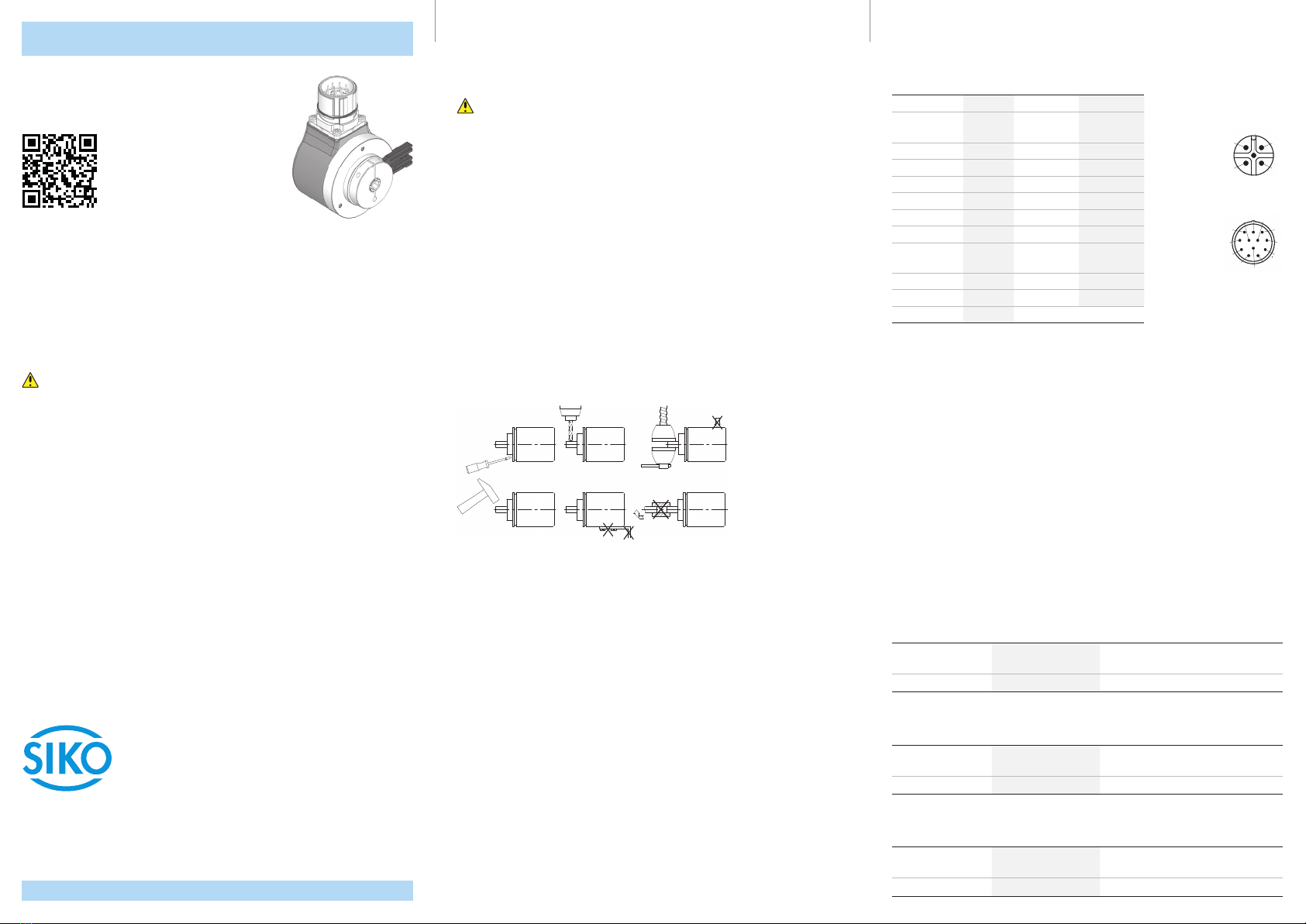
Anbau des Gebers
• Die Befestigung erfolgt mittels Schrauben oder Federelement und Klem-
mung der Welle. Montieren Sie den Inkrementalgeber möglichst verspan-
nungsfrei.
• Kräfte dürfen nicht durch das Gehäuse übertragen werden. Sie dürfen aus-
schließlich an der Welle des Geräts wirken.
• Beachten Sie die maximalen axialen und radialen Wellenbelastungen.
• Achten Sie auf geringen Wellen- und Winkelversatz. Bei nicht korrekter axi-
aler oder winkliger Stellung zwischen Welle und Flansch entstehen Span-
nungen im Lager, die über erhöhte Erwärmung bis zur Zerstörung der Lager
führen können.
Elektrischer Anschluss
Der Einsatzort ist so zu wählen, dass induktive oder kapazitive Störungen nicht
auf den Inkrementalgeber oder dessen Anschlussleitung einwirken können!
• Nur geschirmtes Kabel verwenden. Den Kabelschirm beidseitig auflegen.
• Die Verdrahtung von Abschirmung und Masse (GND) muss sternförmig und
großflächig erfolgen.
• Leitungsführungen parallel zu Energieleitungen vermeiden. Schirmbleche
oder metallisierte Gehäuse verwenden.
Belegung
Nicht verwendete Adern sind vor Inbetriebnahme einzeln zu isolieren.
Signal Farbe E1
(OP, LD)
Pin E12
(PP)
Pin E2
(OP, LD)
/B rosa - - - 1
+SUB (Sense-
Leitung)
rotblau - - - 2
0blau 5 3
/0 rot - - - 4
Agrün 3 5
/A gelb - - - 6
Bgrau 4 8
GND weiß 1 10
SGND (Sense-
Leitung)
graurosa - - - 11
+UB braun 212
nc - - - - - - 7, 9
Schirm auf Steckergehäuse
Inbetriebnahme
Bitte beachten Sie die Hinweise auf ordnungsgemäßen mechanischen und elek-
trischen Anschluss. Nur dann sind die Voraussetzungen für eine problemlose
Inbetriebnahme und einwandfreien Betrieb gegeben.
Prüfen Sie vor der Inbetriebnahme insbesondere nochmals auf:
• korrekte Polung der Betriebsspannung.
• korrekten Anschluss des Kabels und der Signale.
• festen Sitz des Gebers.
Die Betriebsspannung des Gebers muss gemeinsam mit der der Folgeelektronik
(z. B. Steuerung) eingeschaltet werden, um Latchup-Eekte an den Ausgängen
des Gebers zu vermeiden.
--> Nehmen Sie den Geber elektrisch in Betrieb.
Technische Daten
Elektrische Daten
Ausgangsschaltung PP
Ergänzung
Betriebsspannung 10 … 30VDC verpolsicher, das eingesetzte Netzteil
entspricht Class 2 (UL 1310)
Stromaufnahme typisch 50mA ≤100mA (ohne Last)
Elektrische Daten
Ausgangsschaltung OP
Ergänzung
Betriebsspannung 10 … 30VDC verpolsicher, das eingesetzte Netzteil
entspricht Class 2 (UL 1310)
Stromaufnahme typisch 50mA ≤100mA (ohne Last)
Elektrische Daten
Ausgangsschaltung LD
Ergänzung
Betriebsspannung 5 … 30VDC verpolsicher, das eingesetzte Netzteil
entspricht Class 2 (UL 1310)
Stromaufnahme typisch 40mA ≤90mA (ohne Last)
3
1
4
5
2
Ansichtseite =
Steckseite
Stiftkontakt
9
11
12
4
3
2
5
1
6
7
8
10
Ansichtseite =
Steckseite
Stiftkontakt
Quick Start Guide
IH5815 · Date 27.09.2022 · Art. No. 89300 · Mod. status 194/22
SIKO GmbH
Weihermattenweg 2
79256 Buchenbach
www.siko-global.com
Phone: +49 7661 394-0
Fax: + 49 7661 394-388
Service: suppor[email protected]
IH5815
Incremental encoder
For detailed documentation please refer under
http://www.siko-global.com/p/ih5815
General information
Prior to installation, including in hazard areas, read the Installation Instruc-
tion (download from the internet). It contains the safety instructions, hints
and technical data to be observed during installation. Subject to change with-
out notice.
Caution
In order to ensure reliable functioning of this product, take care to transport,
store, position and mount it appropriately. Exercise care when you operate and
maintain the device. Only properly qualified personnel is authorized to install
and operate this product.
Safety information
It is important for safety reasons that you read and understand the below
instructions before you install the system:
• Installation, connection, commissioning and maintenance shall be done by
properly qualified personnel.
• It is the responsibility of the customer to ensure that the personnel con-
cerned read and follow the instructions and directions of this Guide and of
the Installation Instruction.
• It is the responsibility of the customer to ensure that the incremental
encoder is correctly connected and configured.
• Only personnel specifically trained by SIKO shall execute repair and mainte-
nance work.
Mechanical mounting
For mounting, the degree of protection specified must be observed. If neces-
sary, protect the unit against environmental influences such as sprayed water,
dust, knocks, extreme temperatures.
Notice!
Radial shaft sealings are subject to wear! Protection class therefore depends on
life and condition of sealings.
Mounting instructions
Please handle the encoder carefully as it is a high-precision device. Especially
do not:
• disassemble or open the encoder.
• link encoder's shaft with rigid couplings as this would expose the encoder's
shaft bearing to high forces.
• knock on casing or shaft; the encoder's inner components could be dam-
aged.
• machine (bore, mill ...) flange or shaft. This could lead to severe damage
inside the encoder.
• exceed the values for the maximum axial and radial shaft load.
• mount the encoder incorrectly.
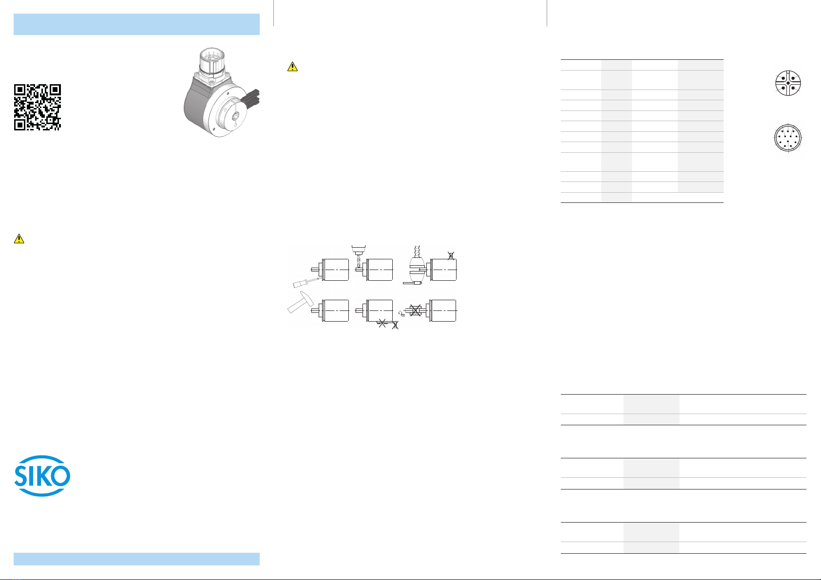
Mounting of the encoder
• Fasten the encoder by means of screws or spring element and clamping of
the shaft. Take care to mount the incremental encoder free from distortion.
• No forces must be transferred through the housing. Forces must act exclu-
sively on the shaft of the instrument.
• Do not exceed the values for the maximum axial and radial shaft load.
• Ensure accurate shaft alignment. If shaft and flange are not correctly
aligned, strain on the bearings will result, which will overheat and be irrep-
arably damaged.
Electrical connection
The location should be selected to ensure that no capacitive or inductive inter-
ferences can aect the incremental encoder or the connection lines!
• Only screened cable should be used.
• Wiring to the screen and ground (GND) must be secured to a good point.
• The running of wiring parallel to the mains supply should be avoided. Use
screening shields or metallized housings.
Assignment
Individually insulate unused cores prior to commissioning.
Signal Color E1
(OP, LD)
Pin E12
(PP)
Pin E2
(OP, LD)
/B pink - - - 1
+SUB (Sense
line)
redblue - - - 2
0blue 5 3
/0 red - - - 4
Agreen 3 5
/A yellow - - - 6
Bgrey 4 8
GND white 1 10
SGND (Sense
line)
greypink - - - 11
+UB brown 212
nc - - - - - - 7, 9
Shielding on connector housing
Commissioning
Please carefully read the information on the encoder's mechanical and electri-
cal connection. This will ensure a trouble free commissioning and operation.
Before operation, please check again:
• that the supply voltage's polarity is correct.
• correct connection of cable and signal lines.
• secure encoder fixation.
The encoder's operating voltage must be switched on together with the down-
stream electronic unit (e. g., control) to avoid latch-up eects on the outputs
of the encoder.
--> Now the encoder can be used.
Technical data
Electrical data
PP output circuit
Additional information
Operating voltage 10 … 30VDC reverse polarity protected, the power supply
unit used complies with Class 2 (UL 1310)
Current consumption typical 50mA ≤100mA (without load)
Electrical data
OP output circuit
Additional information
Operating voltage 10 … 30VDC reverse polarity protected, the power supply
unit used complies with Class 2 (UL 1310)
Current consumption typical 50mA ≤100mA (without load)
Electrical data
LD output circuit
Additional information
Operating voltage 5 … 30VDC reverse polarity protected, the power supply
unit used complies with Class 2 (UL 1310)
Current consumption typical 40mA ≤90mA (without load)
3
1
4
5
2
viewing side =
plug-in side
plug pin
9
11
12
4
3
2
5
1
6
7
8
10
viewing side =
plug-in side
plug pin
Table of contents
Languages:
Other Siko Media Converter manuals


Siko
Siko ProTool SGH50 User manual

Siko
Siko AV58M User manual

Siko
Siko ProTool SGH25 User manual

Siko
Siko SG32 Operation manual

Siko
Siko WV58MR User manual

Siko
Siko ProTool SGH25 User manual

Siko
Siko SGH10L User manual

Siko
Siko SG32 User manual

Siko
Siko WH3650M User manual

Siko
Siko WV36M/SSI Operation manual


