Siko IG16 Operation manual

IG06, IG16, IG07, IG17 Datum 25.03.2013 Art.Nr. 79650 Änd. Stand 106/13 1
IG06
IG07
IG16
IG17
Hohlwellengeber Vollwellengeber
Abb. 1: Montagehinweise
DEUTSCH
1. Gewährleistungshinweise
• LesenSievorderMontageundderInbetriebnahme
diesesDokumentsorgfältigdurch.BeachtenSiezu
IhrereigenenSicherheitundderBetriebssicherheit
alle Warnungen und Hinweise.
• Ihr Produkt hat unser Werk in geprüftem und
betriebsbereitem Zustand verlassen. Für den
BetriebgeltendieangegebenSpezifikationenund
die Angaben auf dem Typenschild als Bedingung.
• Garantieansprüche gelten nur für Produkte der
Firma SIKO GmbH. Bei dem Einsatz in Verbindung
mitFremdproduktenbestehtfürdasGesamtsystem
kein Garantieanspruch.
• Reparaturen dürfen nur im Werk vorgenommen
werden. Für weitere Fragen steht Ihnen die Firma
SIKO GmbH gerne zur Verfügung.
2. Identifikation
Das Typenschild zeigt den Gerätetyp mit Varianten-
nummer. Die Lieferpapiere ordnen jeder Varianten-
nummer eine detaillierte Bestellbezeichnung zu.
z. B. IG07-0023
Varianten-Nr.
Geräte-Typ
3. Mechanische Montage
Die Montage darf nur gemäß der angegebenen IP-
Schutzart vorgenommen werden. Das Gerät muss
ggfs. zusätzlich gegen schädliche Umwelteinflüsse,
wie z. B. Spritzwasser, Staub, Schläge, Temperatur
geschützt werden.
Achtung! Radialdichtringe sind Verschleißteile!
Die Schutzart ist deshalb abhängig von Lebensdau-
er und Zustand der Dichtringe.
Montagehinweise
Gehen Sie sorgfältig mit dem Geber um. Es handelt
sich um ein Präzisionsmessgerät. Folgende Punkte
führen unverzüglich zum Verfall der Garantie:
• ZerlegenoderÖnen desGebers(soweitdiesnicht
in dieser Benutzerinformation beschrieben wird).
• Unsachgemäße Kupplung der Geberwelle z. B. mit
steifen Kupplungen, die zu große Kräfte auf die
LagerungderGeberwelleerzeugen.VerwendenSie
beiVolwellengeberndieSIKO-Ausgleichskupplung
Typ AK18.
• Schläge auf den Geber oder die Welle, da dadurch
interneElementewiez.B.dieoptischeKodescheibe
beschädigt werden können.
• MechanischeBearbeitungderWelle,desFlansches
oder Gehäuses (Bohren, Fräsen, usw.). Hierdurch
kann es zu schweren Beschädigungen der inneren
Teile des Gebers kommen.
• Unzulässige axiale oder radiale Belastung der
Welle.
• Unsachgemäße Befestigung des Gebers.
Was Sie nicht tun sollten
Benutzerinformation
IG06, IG16, IG07, IG17
Inkrementalgeber
Anbau des Gebers
• Die Befestigung erfolgt mittels Schrauben oder
DrehmomentabstützungundKlemmungderWelle.
MontierenSiedenGebermöglichstverspannungs-
frei und mit Drehmomentstütze.

2 IG06, IG16, IG07, IG17 Datum 25.03.2013 Art.Nr. 79650 Änd. Stand 106/13
• Kräfte dürfen nicht durch das Gehäuse übertragen
werden.Siedürfen ausschließlichan derWelledes
Geräts wirken.
• Beachten Sie die maximalen axialen und radialen
Wellenbelastungen.
• AchtenSieaufgeringenWellen-undWinkelversatz.
Bei nicht korrekter axialer oder winkliger Stellung
zwischenWelleundFlanschentstehenSpannungen
im Lager, die über erhöhte Erwärmung bis zur
Zerstörung der Lager führen können.
4. Elektrischer Anschluss
• Steckverbindungen dürfen nie unter Spannung
gesteckt oder abgezogen werden!
• AlleVerdrahtungsarbeitendürfennurspannungs-
los erfolgen.
• Litzen sind mit geeigneten Aderendhülsen zu
versehen.
• Vor dem Einschalten sind alle Leitungsanschlüsse
und Steckverbindungen zu überprüfen.
• Die Betriebsspannung des Gebers muss gemein-
sam mit der der Folgeelektronik (z. B. Steuerung)
eingeschaltet werden.
• Nicht benutzte Signalleitungen sind über einen
Widerstand (z. B. R = 10 kOhm) gegen Masse zu
schalten.
Hinweise zur Störsicherheit
Alle Anschlüsse sind gegen äußere Störeinflüsse
geschützt. Der Einsatzort ist aber so zu wählen,
dass induktive oder kapazitive Störungen nicht
auf das Gerät oder deren Anschlussleitungen
einwirken können! Störungen können z.B. von
Schaltnetzteilen, Motoren, getakteten Reglern
oder Schützen verursacht werden. Durch geeignete
Kabelführung und Verdrahtung können Störeinflüs-
se vermindert werden.
Erforderliche Maßnahmen:
• Nur geschirmtes Kabel verwenden. Den Kabel-
schirm beidseitig auflegen. Litzenquerschnitt der
Leitungen min. 0,14 mm², max. 0,5 mm².
• Die Verdrahtung von Abschirmung und Masse (0 V)
muss sternförmig und großflächig erfolgen.
• DasSystemmussinmöglichstgroßemAbstandvon
Leitungen eingebaut werden, die mit Störungen
belastet sind;ggfs. sind zusätzliche Maßnahmen
wie Schirmbleche oder metallisierte Gehäuse
vorzusehen. Leitungsführungen parallel zu Ener-
gieleitungen vermeiden.
• Schützspulen müssen mit Funkenlöschgliedern
beschaltet sein.
Spannungsversorgung
Die Spannungswerte sind abhängig von der Geräte-
ausführung und sind den Lieferpapieren oder dem
Typenschild zu entnehmen.
10 ... 30 VDC (PP, PN, OP, ON, OE, OC, LD24)
5 VDC ± 5% (LD)
Allgemeine Hinweise
Bitte beachten Sie:
• Löten Sie nur mit dem Feinlötkolben (15 ... max.
50 Watt Leistung).
• Verwenden Sie nur Lötdraht Pb Sn 60 mit Kolo-
phonium als Flußmittel (DIN 8516)
• Zur einfachen Montage muss der Kabelmantel
gegenüber dem Schirm verschiebbar sein.
• Verwenden Sie möglichst nur die in der folgenden
Tabelle empfohlenen geschirmten Kabel.
Ausgangsschal-
tung
Kabelempfehlung Aussen-
durchmesser
IG06, IG16:
PP, OC LiYCY 5x0,25 mm² ca. 5,4 mm
IG07, IG17:
PP, PN
OP , ON (AXX, AX0,
ABX, AXI)
OP, ON, OC, OE
(AB0, ABI)
LD, LD24
LiYCY 5x0,5 mm²
LiYCY 7x0,38 mm²
LiYCY 10x0,25 mm²
2-LiYCY 12x0,14 mm²,
paarweise verdrillt
ca. 7,2 mm
ca. 6,8 mm
ca. 7,3 mm
ca. 7,8 mm
4.1 Anschlussart E1/...
Ausgangsschaltung PP, OC (IG06, IG16):
Ausgangsschaltung PP, PN (IG07, IG17):
Farbe Belegung
grau GND
gelb Kanal A
weiß Kanal B
grün Kanal 0/I
braun +UB
Ausgangsschaltung OP, ON (IG07, IG17 Ausführung
AXX, AX0, AXI, ABX):
Farbe Belegung
grau GND
gelb Kanal A
weiß Kanal B; 0
braun +UB
rosa Kanal /A
blau Kanal /B; I

IG06, IG16, IG07, IG17 Datum 25.03.2013 Art.Nr. 79650 Änd. Stand 106/13 3
Ausgangsschaltung OP, ON, OC, OE (IG07, IG17 Aus-
führung AB0, ABI):
Farbe Belegung
gelb Kanal A
weiß Kanal B
grün Kanal 0
rosa Kanal /A
blau Kanal /B
violett Kanal I
grau GND
schwarz GND
braun +UB
rot +UB
Ausgangsschaltung LD, LD24 (IG07, IG17):
Farbe Belegung
gelb Kanal A
grün Kanal /A
grau GND
rosa +UB
weiß Kanal B
braun Kanal /B
rot +SUB (Fühlerleitung nur bei LD)
blau SGND (Fühlerleitung nur bei LD)
rotblau Kanal 0
graurosa Kanal I
schwarz GND
violett +UB
Bei Ausgangsschaltung "LD" ist eine Kabellänge
von max. 100m möglich, wenn der Geber mit einem
Netzteil versorgt wird, welches dafür sorgt, dass am
Geber 5 V anliegen. Das Netzgerät muss für den An-
schluss der "Sense"-Leitungen (+SUB und SGND)
vorbereitet sein.
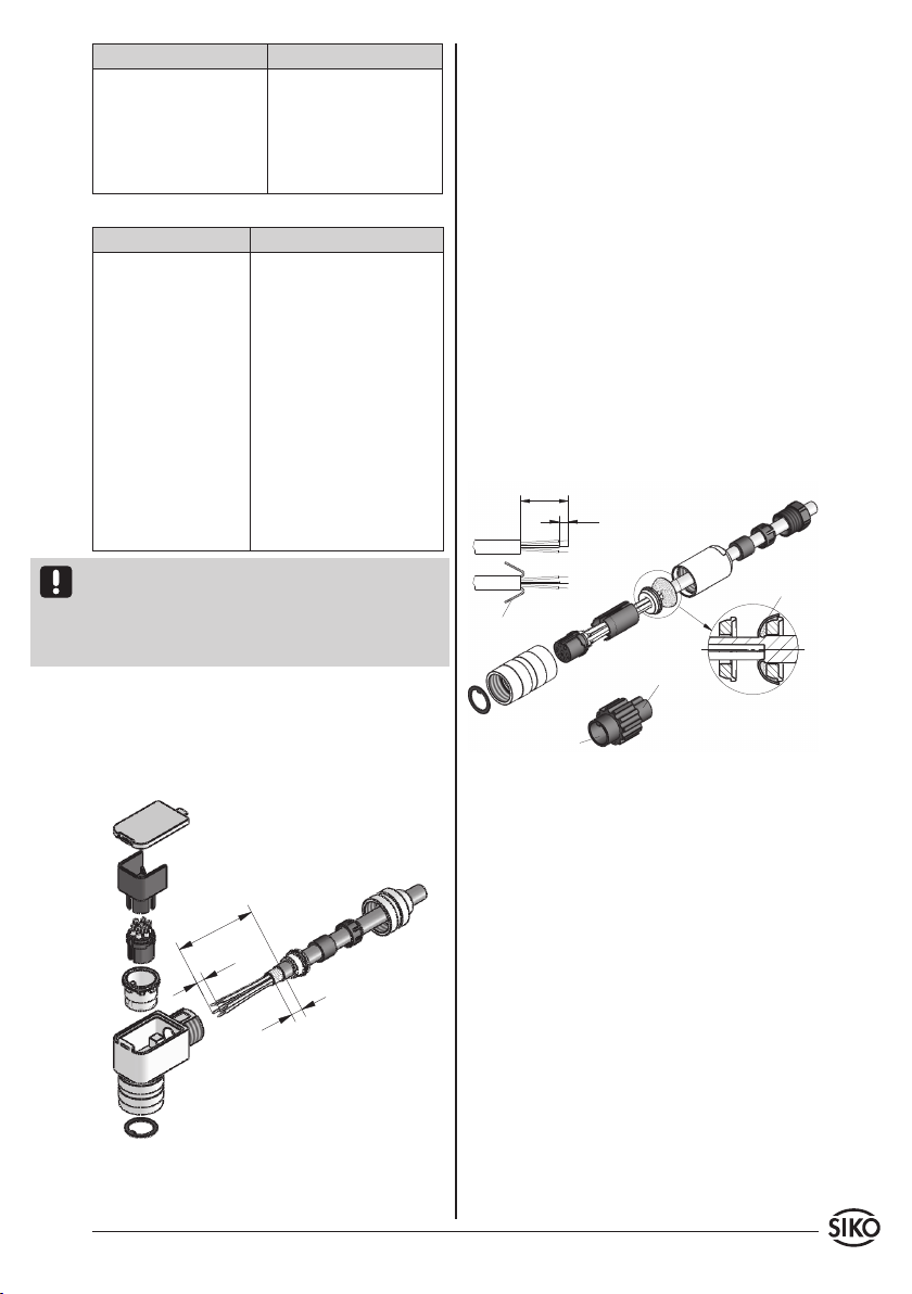
4.2 Anschlussart E3/...; E4/...; E6/... (Kabellänge
max. 100 m); EX (ohne Gegenstecker; IG07, IG17)
Anschlussart E3/.. (IG07, IG17)
Gehen Sie schrittweise vor:
1. Dichtungen (1) montieren (3x).
2. Druckschraube (6), Klemmkorb (2), Dichtring,
Schirmring (5) auf das Kabel auädeln.
3. Kabelabmanteln,Schirmkürzen,Leiter abisolie-
ren und verzinnen.
4. Litzen durch das Gehäuse (4) führen.
5. Schirmring (5) und Klemmkorb (2) montieren.
6. Druckschraube (6) leicht andrehen.
7. Litzen nach Anschlussplan an Kontakteinsatz
(7) löten.
8. Positionshülse (8) in Winkelstellung montieren.
9. Kontakteinsatz (7) und Distanzhülse (9) ein-
setzen.
10.Deckel (10) einhaken.
11.Druckschraube (6) festziehen (ca. 10-20 Ncm).
Anschlussart E4/.. (IG07, IG17) und E6/.. (IG06,
IG16) mit Kupplungsdose.
Gehen Sie schrittweise vor:
1. Pos. 6 ... 10 über Kabelmantel schieben.
2. Kabel abisolieren.
3. Schirm umlegen.
4. Pos. 5 auf Litzen schieben.
5. Litzen an Pos. 3 löten (entspr. Anschlussplan).
6. Abstandhülse Pos. 4 aufweiten und über Litzen
stülpen, zusammendrücken und auf Pos. 3
stecken. Schlitz und Nut (Pos. 3 und 4) müssen
deckungsgleich sein.
7. Pos. 6 an Pos. 5 drücken, überstehender Schirm
abschneiden.
8. Pos. 2 und 7 aufschieben und mittels Montage-
werkzeug Pos. 11 verschrauben.
9. Pos.8inPos.9stecken,beidesinPos.7schieben.
10.Pos. 10 mit Pos. 7 verschrauben.
11.Pos. 1 in Pos 2. schieben.

4 IG06, IG16, IG07, IG17 Datum 25.03.2013 Art.Nr. 79650 Änd. Stand 106/13
Schirm
Schirm
Stiftteil
Buchsenteil
Ansichtseite = Steckseite
Stiftkontakt Geräteseite
Ansichtseite = Lötseite
Buchsenkontakt Gegenstecker
Ansichtseite = Steckseite
Stiftkontakt Geräteseite
Ansichtseite = Lötseite
Buchsenkontakt Gegenstecker
Ansichtseite =
Steckseite
Ansichtseite = Steckseite
Stiftkontakt Geräteseite
Ansichtseite = Lötseite
Buchsenkontakt Gegenstecker
Ansichtseite = Steckseite
Stiftkontakt Geräteseite
Ansichtseite = Lötseite
Buchsenkontakt Gegenstecker
Ansichtseite = Steckseite
Ausgangsschaltung LD, LD24 (IG07, IG17):
Pin Farbe Belegung
A gelb Kanal A
B grün Kanal /A
C grau GND
D rosa +UB
E weiß Kanal B
F braun Kanal /B
Grot +SUB
H blau SGND
J rotblau Kanal 0
K graurosa Kanal I
L schwarz GND
M violett +UB
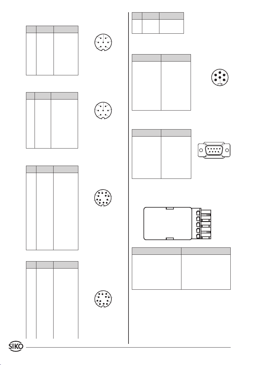
4.3 Anschlussart E7/... (IG06, IG16)
Ausgangsschaltung PP 6-pol. Buchsenkontakt:
Pin Belegung
1 +24V
2 Ch1
3 Ch2
4 - - -
5 0V
6 - - -
Lötöse Schirm
4.4 Anschlussart E8/... (IG06, IG16, IG07, IG17)
9-pol. D-SUB Stiftkontakt:
Pin Belegung
1 +UB
2 Kanal A
3 Kanal B
4 Kanal 0/I
5 GND
6 - 9 - - -
4.5 Anschlussart E9/... (IG06)
Stecker 5-pol. der Fa.WAGO:
Ausgangsschaltung PP
Ausgangsschaltung PP, OC (IG06, IG16) 7-pol.:
Ausgangsschaltung PP, PN (IG07, IG17) 7-pol.:
Pin Farbe Belegung
1 grau GND
2 gelb Kanal A
3 weiß Kanal B
4 grün Kanal 0/I
5 braun +UB
6, 7 - - - - - -
Ausgangsschaltung OP, ON (IG07, IG17 Ausführung
AXX, AX0, AXI, ABX) 7-pol.:
Pin Farbe Belegung
1 grau GND
2 gelb Kanal A
3 weiß Kanal B; 0
4 - - - - - -
5 braun +UB
6 rosa Kanal /A
7 blau Kanal /B; I
Ausgangsschaltung OP, ON, OC, OE (IG07, IG17
Ausführung AB0, ABI) 12-pol.:
Pin Farbe Belegung
A gelb Kanal A
B weiß Kanal B
C grün Kanal 0
D rosa Kanal /A
E blau Kanal /B
F violett Kanal I
G grau GND
H schwarz GND
J braun +UB
Krot +UB
L, M - - - - - -

IG06, IG16, IG07, IG17 Datum 25.03.2013 Art.Nr. 79650 Änd. Stand 106/13 5
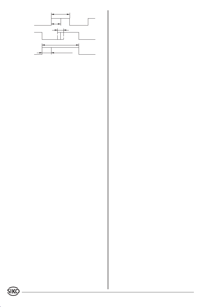
Abb. 2: Impulsbild
Pin Belegung
1 +UB
2 Kanal B
3 Kanal A
4 X
5 GND (Schirm)
5. Inbetriebnahme
Bitte beachten Sie die Hinweise auf ordnungsge-
mäßen mechanischen und elektrischen Anschluss.
Nur dann sind die Voraussetzungen für eine pro-
blemlose Inbetriebnahme und einwandfreien Be-
trieb gegeben.
Prüfen Sie vor der Inbetriebnahme insbesondere
nochmals auf:
• korrekte Polung der Betriebsspannung.
• korrekten Anschluss des Kabels und der Signale.
• festen Sitz des Gebers und der Hohlwelle.
Die Betriebsspannung des Gebers muss gemein-
sam mit der der Folgeelektronik (z. B. Steuerung)
eingeschaltet werden, um Latchup-Eekte an den
Ausgängen des Gebers zu vermeiden.
--> Nehmen Sie den Geber elektrisch in Betrieb.
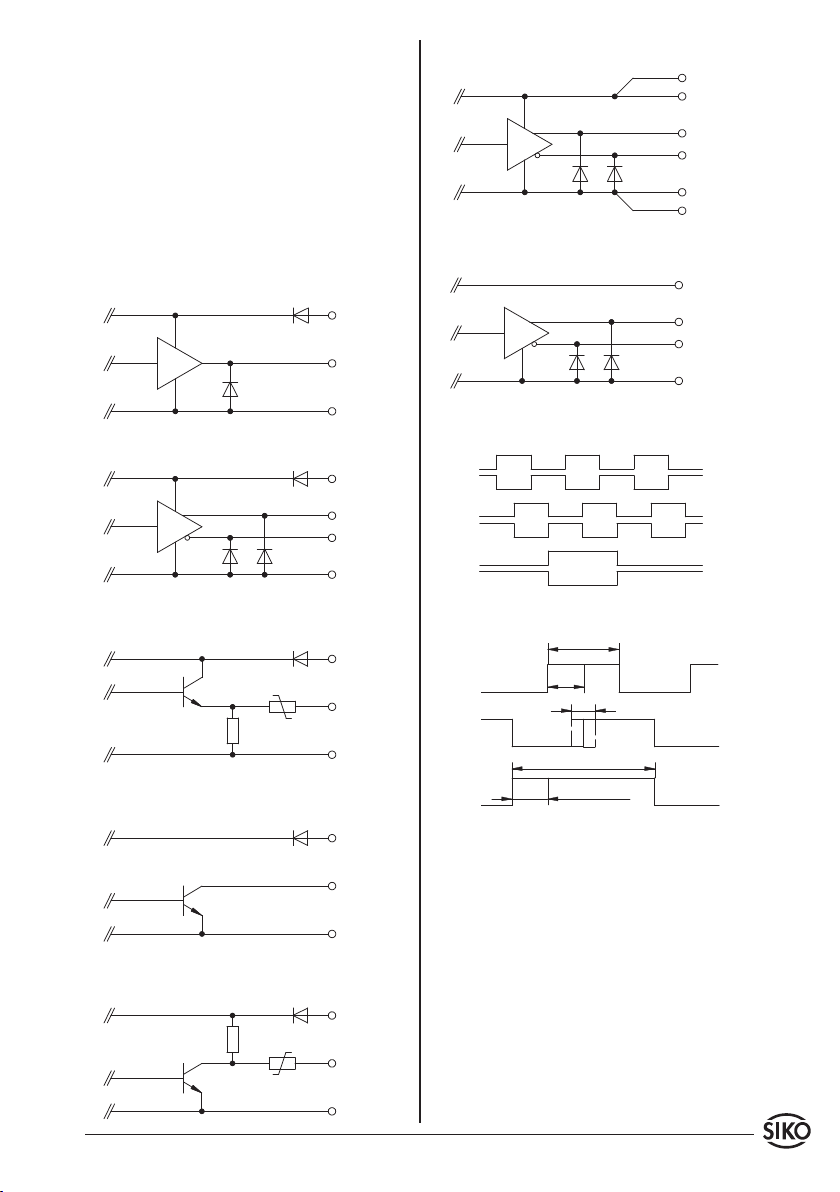
6. Ausgangsschaltungen
PP, Gegentakt (Push-Pull); IG06, IG16
PP, PN, Gegentakt (Push-Pull); IG07, IG17
OP, ON, Gegentakt (Push-Pull), dierentiell; IG07,
IG17
OE, Oener Emitter, NPN-Typ, dierentiell; IG07,
IG17
OC, Oener Kollektor, NPN-Typ; IG06, IG16
OC, Oener Kollektor, NPN-Typ, dierentiell IG07,
IG17
LD, Leitungstreiber, dierentiell; IG07, IG17
LD24, Leitungstreiber, dierentiell; IG07, IG17
6.1 Ausgangssignale / Impulsbild
6 IG06, IG16, IG07, IG17 Datum 25.03.2013 Art.Nr. 79650 Änd. Stand 106/13
Abb. 3: Timing, Signale Inkrementalgeber

IG06, IG16, IG07, IG17 Datum 25.03.2013 Art.Nr. 79650 Änd. Stand 106/13 7
IG06
IG07
IG16
IG17
Hollow shaft encoder Solid shaft encoder
Fig. 1: Mounting instructions
ENGLISH
1. Warranty information
• In order to carry out installation correctly, we
strongly recommend this document is read very
carefully. This will ensure your own safety and the
operating reliability of the device.
• Yourdevicehasbeenqualitycontrolled,testedand
is ready for use. Please observe all warnings and
information which are marked either directly on
the device or specified in this document.
• Warranty canonly beclaimed for componentssup-
pliedbySIKOGmbH.If the system is used together
with other products, there is no warranty for the
complete system.
• Repairs should be carried out only at our works.
If any information is missing or unclear, please
contact the SIKO sales sta.
2. Identification
Please check the particular type of unit and type
number from the identification plate. Type number
and the corresponding version are indicated in the
delivery documentation.
e. g. IG07-0023
version number
type of unit
3. Installation
For mounting, the degree of protection specified
must be observed. If necessary, protect the unit
against environmental influences such as sprayed
water, dust, knocks, extreme temperatures.
Important information! Radial shaft sealings are
subject to wear! Protection class therefore depends
on life and condition of sealings.
Mounting instructions
Please handle the encoder carefully as it is a high-
precision device.
Especially do not:
• disassembleoropentheencoder(unlessstipulated
in this brochure).
• link encoder's shaft with rigid couplings as this
would expose the encoder's shaft bearing to high
forces. For solid shaft encoders we recommend
the use of SIKO flexible shaft coupling type AK18.
• knockoncasingor shaft; theencoder'sinner com-
ponents (e. g. the coded disk) could be damaged.
• machine (bore, mill ...) flange or shaft. This could
lead to severe damage inside the encoder.
• exceed the values for the maximum axial and
radial shaft load.
• mount the encoder incorrectly.
Otherwise manufacturer's warranty will be invalida-
ted!
NEVER ...
User Information
IG06, IG16, IG07, IG17
Incremental encoder
Mounting of the encoder
• Fixationeitherbyscrewsorviatorquepinandshaft
clamping. Ensure that the encoder is mounted
without strain and use torque pin.
• Forces must not be transmitted via the housing,
but only via the shaft.
• Do not exceed the values for the maximum axial
and radial shaft load.

8 IG06, IG16, IG07, IG17 Datum 25.03.2013 Art.Nr. 79650 Änd. Stand 106/13
• Ensure accurate shaft alignment. If shaft and
flange are not correctly aligned, strain on the
bearings will result, which will overheat and be
irreparably damaged.
4. Electrical connection
• Switch power o before any plug is inserted or
removed!
• Anywiringmustonlybecarriedoutwithoutpower.
• Provide stranded wires with ferrules.
• Check all lines and connections before switching
on the equipment.
• The encoder's and follower electronic's (e. g.
control unit) operating supply must be switched
on simultaneously.
• Encoderswithparalleloutput:Unconnectedsignal
lines must be provided with a resistor (e. g.: R =
10 kOhm) and connected to earth.
Interference and distortion
All connections are protected against the eects of
interference. The location should be selected to
ensure that no capacitive or inductive interfe-
rences can aect the encoder or the connection
lines! Suitable wiring layout and choice of cable
can minimise the eects of interference (e. g. in-
terference caused by SMPS, motors, cyclic controls
and contactors).
Necessary measures:
• Only screened cable should be used. Wire cross
section is to be at least 0,14 mm², max. 0,5 mm².
• Wiring to the screen and ground (0 V) must be
secured to a good point.
• The system should be positioned well away from
cableswith interference;if necessarya protective
screen or metal housing must be provided. The
running of wiring parallel to the mains supply
should be avoided.
• Contactor coils must be linked with spark sup-
pression.
Power supply
Supply voltage depends on the unit type and is in-
dicated in the delivery documentation and on the
identification plate.
10 ... 30 V d.c. (PP, PN, OP, ON, OE, OC, LD24)
5 V d.c. ± 5% (LD)
General information
The following points should be observed:
• Use for soldering precision copper bit (perfor-
mance 15 ... 50 Watt max.).
• Use only tin solder wire type Pb Sn 60 with colo-
phonium fluxing agent (DIN 8516).
• Cable outer and screening must be able to slide to
allow easy mounting.
• If possible, use only the sreened cables recom-
mended in the list below.
Output circuit Recommended cable Outside
diameter
IG06, IG16:
PP, OC LiYCY 5x0,25 mm² ca. 5,4 mm
IG07, IG17:
PP, PN
OP, ON (AXX, AX0,
ABX, AXI)
OP, ON, OC, OE (AB0,
ABI)
LD, LD24
LiYCY 5x0,5 mm²
LiYCY 7x0,38 mm²
LiYCY 10x0,25 mm²
2-LiYCY 12x0,14 mm²,
twisted in pairs
ca. 7,2 mm
ca. 6,8 mm
ca. 7,3 mm
ca. 7,8 mm
4.1 Connection type E1/...
Output circuit PP, OC (IG06, IG16):
Output circuit PP, PN (IG07, IG17):
Color Designation
grey GND
yellow channel A
white channel B
green channel 0/I
brown +UB
Output circuit OP, ON (IG07, IG17 version AXX, AX0,
AXI, ABX):
Color Designation
grey GND
yellow channel A
white channel B; 0
brown +UB
pink channel /A
blue channel /B; I
Output circuit OP, ON, OC, OE (IG07, IG17 version
AB0, ABI):
Color Designation
yellow channel A
white channel B
green channel 0
pink channel /A
blue channel /B
IG06, IG16, IG07, IG17 Datum 25.03.2013 Art.Nr. 79650 Änd. Stand 106/13 9
screening
screening
pin
socket
Color Designation
violet channel I
grey GND
black GND
brown +UB
red +UB
Output circuit LD, LD24 (IG07, IG17):
Color Designation
yellow channel A
green channel /A
grey GND
pink +UB
white channel B
brown channel /B
red +SUB (send line with LD only)
blue SGND (send line with LD only)
redblue channel 0
greypink channel I
black GND
violet +UB
With output circuit 'LD' max. cable length is 100 m,
provided that the encoder is combined with a power
supply unit feeding the encoder with 5 V. The power
supply unit must allow connection of the "Sense"
lines (+SUB and SGND).
4.2 Connection type E3/...; E4/...; E6/... (cable
length max. 100 m); EX (without mating connector;
IG07, IG17)
Connection type E3/.. (IG07, IG17)
Please proceed as follows:
1. Mount seals (1) (3x).
2. Stringingpressingscrew(6),pinchring(2),seal,
shielding ring (5)
3. Dismantle cable, shorten screening, strip and
tin conductor.
4. Thread-up wires thruogh the housing (4).
5. Mount shielding ring (5) and pinch ring (2).
6. Turn on the pressing screw (6) very slightly.
7. Solder wires on insert (7).
8. Mount positioning sleeve (8) in angled position.
9. Set in insert (7) and distance sleeve (9).
10.Mount cover (10).
11.Fix pressing screw (6) (approx. 10-20 Ncm).
Connection type E4/.. (IG07, IG17) and E6/..
(IG06, IG16) with coupling (socket)
Please proceed as follows:
1. Slip parts 6 to 10 over outer cable.
2. Strip cable.
3. Turn down screening.
4. Push part 5 onto ferrules.
5. Solderstrandedwiresatpart3(followconnection
diagram).
6. Open spacer (part 4) and put it over ferrules,
squeeze and push it onto part 3. Slot and keyway
of parts 3 and 4 must align.
7. Press parts 6 and 5 together; cut prodruding
screening.
8. Push parts 2 and 7 together and screw part 11
using appropriate tool.
9. Push part 8 into part 9 and slide both parts
into part 7.
10.Screw parts 10 and 7 together.
11.Push part 1 into part 2.
10 IG06, IG16, IG07, IG17 Datum 25.03.2013 Art.Nr. 79650 Änd. Stand 106/13
viewing side =
plug-in side
viewing side =
plug-in side
viewing side = plug-in side
plug pin unit side
viewing side = soldering side
socket contact mating connector
viewing side = plug-in side
plug pin unit side
viewing side = soldering side
socket contact mating connector
viewing side = plug-in side
plug pin unit side
viewing side = soldering side
socket contact mating connector
viewing side = plug-in side
plug pin unit side
viewing side = soldering side
socket contact mating connector
Pin Color Designation
L black GND
M violet +UB
4.3 Connection type E7/... (IG06, IG16)
Output circuit PP 6 pole socket contact:
Pin Designation
1 +24V
2 Ch1
3 Ch2
4 - - -
5 0V
6 - - -
soldering tag screening
4.4 Connection type E8/... (IG06, IG16, IG07, IG17)
9-pol. D-SUB plug pin:
Pin Designation
1 +UB
2 channel A
3 channel B
4 channel 0/I
5 GND
6 - 9 - - -
4.5 Connection type E9/... (IG06)
5-pole plug, WAGO type:
Output circuit PP
Output circuit PP, OC (IG06, IG16) 7 pole:
Output circuit PP, PN (IG07, IG17) 7 pole:
Pin Color Designation
1grey GND
2 yellow channel A
3 white channel B
4 green channel 0/I
5 brown +UB
6,7 - - - - - -
Output circuit OP, ON (IG07, IG17 version AXX, AX0,
AXI, ABX) 7 pole:
Pin Color Designation
1grey GND
2 yellow channel A
3 white channel B; 0
4 - - - - - -
5 brown +UB
6 pink channel /A
7 blue channel /B; I
Output circuit OP, ON, OC, OE (IG07, IG17 version
AB0, ABI) 12 pole:
Pin Color Designation
A yellow channel A
B white channel B
C green channel 0
D pink channel /A
E blue channel /B
F violet channel I
Ggrey GND
H black GND
J brown +UB
Kred +UB
L,M - - - - - -
Output circuit LD, LD24 (IG07, IG17) 12 pole:
Pin Color Designation
A yellow channel A
B green channel /A
Cgrey GND
D pink +UB
E white channel B
F brown channel /B
Gred +SUB
H blue SGND
J redblue channel 0
Kgreypink channel I
Pin Designation
1 +UB
2 channel B
3 channel A
4 X
5 GND (screening)
5. Commissioning
Please carefully read the information on the
encoder's mechanical and electrical connection.
This will ensure a trouble free commissioning and
operation.
Before operation, please check again:
• that the supply voltage's polarity is correct.
IG06, IG16, IG07, IG17 Datum 25.03.2013 Art.Nr. 79650 Änd. Stand 106/13 11
Fig. 2: Wave form
Fig. 3: Timing, incremental encoder signals
OP, ON (Push-Pull), dierential; IG07, IG17
• correct connection of cable and signal lines
• secure encoder fixation on the hollow shaft.
The encoder's and follower electronic's (e. g. con-
trol unit) operating supply must be switched on
simultaneoulsy to avoid latch-up eects on the
encoder's outputs.
--> Now the encoder can be used.
6. Output circuits
PP (Push-Pull); IG06, IG16
PP, PN (Push-Pull); IG07, IG17
OE, Open Emitter, NPN-type, dierential; IG07,
IG17
OC, Open Collector, NPN-type; IG06, IG16
OC, Open Collector, NPN-type, dierential; IG07,
IG17
LD, Line Driver, dierential; IG07, IG17
LD24, Line Driver, dierential; IG07, IG17
6.1 Output signals / Wave form

12 IG06, IG16, IG07, IG17 Datum 25.03.2013 Art.Nr. 79650 Änd. Stand 106/13
SIKO GmbH
Werk/Factory:
Weihermattenweg 2
79256 Buchenbach-Unteribental
Postanschrift / Postal address:
Postfach 1106
79195 Kirchzarten
Telefon/Phone +49 7661 394-0
Telefax/Fax +49 7661 394-388
E-Mail info@siko.de
Internet www.siko.de
Service suppor[email protected]
This manual suits for next models
3
Table of contents
Languages:
Other Siko Media Converter manuals


Siko
Siko WV42HD User manual

Siko
Siko ProTool SGH10 User manual

Siko
Siko WV58MR User manual

Siko
Siko ProTool SGH25 User manual

Siko
Siko WV36M/CAN User manual

Siko
Siko WH3650M User manual

Siko
Siko ProTool SGH50 User manual

Siko
Siko ProTool SGH10 User manual

Siko
Siko WH58MR User manual

Siko
Siko ProTool SGH25 User manual


