Specifications
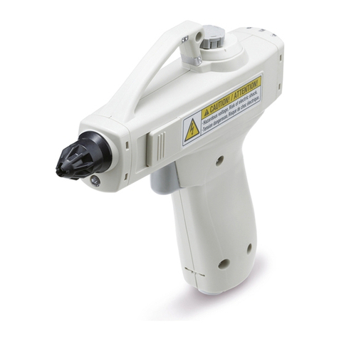
Parts Description
Description of LED Indicators
AC Adapter Specifications
Input voltage*4100 to 240 VAC
50/60 Hz
Output voltage 24 VDC ±5%
Output current 0.8 A max.
Ambient
temperature 0 to 40°C
Ambient humidity 20 to 80%RH
Safety standards IEC 62368-1
*4 An AC cord included with an AC adapter is only
for use in Japan. (Rated voltage 125 V, Plug
JIS C 8303, Inlet IEC 60320-C13)
LED Indicators
No. Display LED color Description Contents
qPWR Green Power supply
indicator
Green LED turns ON when power is supplied, and the LED
flashes when the voltage is outside of the specification range.
wION/
HV
Green/
Red
Static neutralization
operation/Incorrect
high voltage indicator
Green LED turns ON during static neutralization.
Red LED turns ON when a high voltage abnor-
mality is present.
eNDL Green Maintenance
indicator
Green LED turns ON when lowered static
neutralization performance due to the con-
tamination or wear of the emitter is detected.
wq e
w r
y
t
u
q
Ionizer model IZG10
Ion generation method Corona discharge type
Method of applying high voltage High frequency AC type
Applied voltage*1±2.5 kV
Offset voltage*2Within ±10 V
Air supply*3
Fluid Air (Clean, dry air)
Operating pressure 0.05 to 0.6 MPa
Connecting tube size ø8 (Metric), ø5/16" (Inch)
Power supply voltage 24 VDC ±10% (21.6 to 26.4 V)
Current consumption 90 mA (typ.)
Ambient temperature 0 to 40°C (No freezing)
Ambient humidity 35 to 65%RH (No condensation)
Material Case: PBT Emitter: Tungsten
Weight
(Body only)
Standard nozzle 200 g
Bypass nozzle 250 g
Standards/Directive CE (EMC directive, RoHS directive), UKCA
*1 Measured with a high pressure probe of 1000 MΩand 5 pF
*2 Measurement value based on a charged plate (Dimensions: 150 mm x 150 mm, Capacitance:
20 pF) as defined in the U.S. ANSI standards (ANSI/ESD STM3.1-2015)
When the distance between the charged plate and the ionizer is 150 mm, and the operating pressure is 0.2 MPa
*3 Static neutralization is not possible without supplying compressed air. Without compressed
air, ozone or nitrogen oxides generated by the ion generation process may accumulate and
adversely affect the product and peripheral equipment.
No. Description Contents
qNozzle Discharge ionized air
wSlide cover
Protective cover for the mode setting switch
eMode setting
switch
Switch for setting blow and trigger
(Default setting: Set no. 0)
r
Flow adjustment
knob (With indicator)
Turn the knob to adjust the flow rate.
Press the knob to lock the setting.
tTrigger
Switch to turn on and off static neutralization
yOne-touch fitting Supply port of compressed air
uPower supply
connector
Connector for power supply, F.G., and
external switch inputs
iLighting LED
Illuminate the object during static neutralization
LED indicator
i
*Inside of the slide cover
e
Alarm
The LEDs are used for notification of malfunctions.
Please note that ion generation may either continue or stop depending on the type of abnormality.
Alarm name Ion generation LED Description Action to reset
alarm
PWR ION/HV NDL
Power supply failure
Stop
Green (Flashing)
OFF OFF
Connected power supply voltage is outside of specification.
Supply power again.
Incorrect high voltage
Stop Green (ON) Red (ON) OFF The high voltage output has dropped.
Supply power again.
CPU failure Stop
Green (Flashing)
Red (Flashing)
Green (Flashing)
CPU error due to noise, etc.
Supply power again.
Maintenance
indication Continue Green (ON) — Green (ON)
When static neutralization performance is reduced
due to contamination, wear, or damage of the emitters
—
186
Gun Type Ionizer IZG10 Series
IZS40/41/42
IZT40/41(-L)/
42(-L)/43(-L)
IZN10EIZFIZG10ZVBIZD10/IZE11IZH10
Antistatic
Equipment
