manuals.online logo
Brands
  1. Home
  2. •
  3. Brands
  4. •
  5. SMC Networks
  6. •
  7. Air Ionizer
  8. •
  9. SMC Networks IZS31 Series User manual

SMC Networks IZS31 Series User manual

Other manuals for IZS31 Series

2

This manual suits for next models

7

Other SMC Networks Air Ionizer manuals

SMC Networks IZT43-L Series User manual

SMC Networks

SMC Networks IZT43-L Series User manual

SMC Networks IZG10 User manual

SMC Networks

SMC Networks IZG10 User manual

SMC Networks IZN10E Series User manual

SMC Networks

SMC Networks IZN10E Series User manual

SMC Networks IZG10 User manual

SMC Networks

SMC Networks IZG10 User manual

SMC Networks IZG10 User manual

SMC Networks

SMC Networks IZG10 User manual

SMC Networks IZT40 Series User manual

SMC Networks

SMC Networks IZT40 Series User manual

SMC Networks IZT43 Series User manual

SMC Networks

SMC Networks IZT43 Series User manual

SMC Networks IZG10 User manual

SMC Networks

SMC Networks IZG10 User manual

SMC Networks IZS31 Series User manual

SMC Networks

SMC Networks IZS31 Series User manual

SMC Networks IZN10E Series Instruction manual

SMC Networks

SMC Networks IZN10E Series Instruction manual

SMC Networks IZS42 User manual

SMC Networks

SMC Networks IZS42 User manual

SMC Networks IZS40-2020-08B-X10 User manual

SMC Networks

SMC Networks IZS40-2020-08B-X10 User manual

SMC Networks IZT41 Series User manual

SMC Networks

SMC Networks IZT41 Series User manual

Popular Air Ionizer manuals by other brands

ESD SYSTEMS 94000 Operation installation and maintenance

ESD SYSTEMS

ESD SYSTEMS 94000 Operation installation and maintenance

TEQOYA TIP9 user guide

TEQOYA

TEQOYA TIP9 user guide

SCS 963E user guide

SCS

SCS 963E user guide

Vessel Stat-Clean F-6BF-E instruction manual

Vessel

Vessel Stat-Clean F-6BF-E instruction manual

Desco SCS 992X-0350 instruction manual

Desco

Desco SCS 992X-0350 instruction manual

BüRGE Ion Dome manual

BüRGE

BüRGE Ion Dome manual

Fraser NEOS 30 OEM manual

Fraser

Fraser NEOS 30 OEM manual

A&D AX-ION-25 instruction manual

A&D

A&D AX-ION-25 instruction manual

greenfan 1600-01 installation instructions

greenfan

greenfan 1600-01 installation instructions

Plasma Air PA600 Series Installation, operation & maintenance manual

Plasma Air

Plasma Air PA600 Series Installation, operation & maintenance manual

Desco 50692 Installation, operation and maintenance manual

Desco

Desco 50692 Installation, operation and maintenance manual

UFO UFO-ECH/10 user manual

UFO

UFO UFO-ECH/10 user manual

Jonix steel 1C Use and maintenance manual

Jonix

Jonix steel 1C Use and maintenance manual

Panasonic TK-AS66-ZEX instruction manual

Panasonic

Panasonic TK-AS66-ZEX instruction manual

Real Spirit AQUA-IONIZER PRO ionHealth Pro owner's manual

Real Spirit

Real Spirit AQUA-IONIZER PRO ionHealth Pro owner's manual

NRD P-2060 instruction manual

NRD

NRD P-2060 instruction manual

Tyent YT20-TL Series user manual

Tyent

Tyent YT20-TL Series user manual

Air Water Life AWL-7000 owner's manual

Air Water Life

Air Water Life AWL-7000 owner's manual

manuals.online logo
manuals.online logoBrands
  • About & Mission
  • Contact us
  • Privacy Policy
  • Terms and Conditions

Copyright 2025 Manuals.Online. All Rights Reserved.

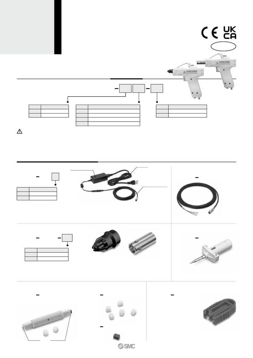
Ionizer
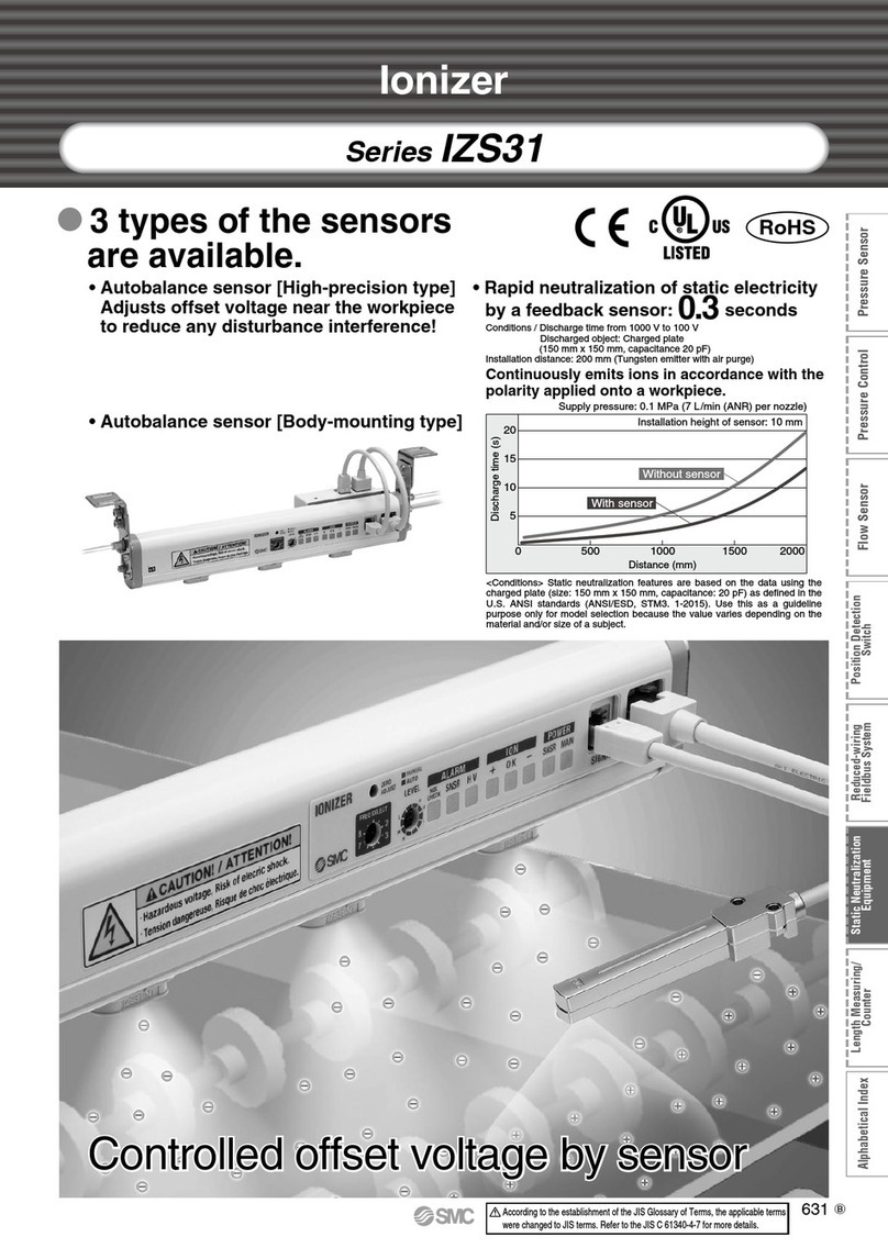
 3 types of the sensors are available.
RoHS compliant
• Autobalance sensor [High-precision type]
Adjusts ion balance near the workpiece
to reduce any interference!
• Autobalance sensor [Body-mounting type]
NewNew
• Rapid elimination of static electricity
by a feedback sensor: 0.3 seconds
Conditions / Static buildup decreased from 1000 V to 100 V
Discharged object: Charged plate
(150 mm x 150 mm, capacitance 20 pF)
Installation distance: 200 mm (Tungsten electrode needle with air purge)
Discharge time (sec)
20
15
10
5
0 500 1000 1500 2000
Installation distance (mm)
With sensor
Without sensor
Installation height of sensor: 10 mm
<Conditions> Static electricity elimination features are based on the data
using the charged plate (size: 150 mm x 150 mm, capacitance: 20 pF) as
defined in the U.S. ANSI standards (ANSI/ESD, STM3, 1-2000). Use this as a
guideline purpose only for model selection because the value varies
depending on the material and/or size of a subject.
Continuously emits ions in accordance with the
polarity applied onto a workpiece.
Supply pressure: 0.1 MPa (7 l/min (ANR) per nozzle)
Series IZS31
Controlled ion balance with sensorsControlled ion balance with sensors
–
+
–
+
–
+
Stop
Static electricity
elimination completion
Ion emission waveformMode
Sensing DC
Energy saving mode
Sensing DC
Continuous static
electricity elimination mode
Pulse DC
+ charged image
Time
Charged voltage
Generates single-polarity ions when
the ion balance is outside ±30 V.
Goes into pulse DC mode when
the ion balance is within ±30 V.
Discharge time [sec]
20
15
10
5
0500 1000 1500 2000
Installation distance L [mm]
Without sensor
Supply pressure: 0.1 MPa (7 l/min (ANR) per nozzle)
Installation height of sensor: 10 mm
Ionizer
Workpiece
L
With sensor
3
2
1
0
–1
–2
–3
1234
Time [sec]
Charged voltage [kV]
With sensor
Without sensor
With sensor
Without sensor
 Rapid elimination of static electricity by a feedback sensor
•
The speed of static electricity elimination has been increased by reading the workpiece’s
electrostatic potential by the feedback sensor and continuously emitting ions with a reverse polarity.
•
Operation mode after static electricity removal (ion balance: within ±30 V) can be selected.
Feedback sensor /
Rapid elimination of static electricity
Feedback sensor
Detects the polarity of a discharged object
and measures the charged voltage.
Energy saving operation mode: Stops generating ions after static electricity removal to reduce power
consumption. Air consumption can also be reduced by controlling a pneumatic valve with a
static electricity removal completion signal.
Note) The pneumatic valve must be separately procured.
Continuous static electricity removal operation mode: After static electricity elimination, the ionizer
changes to pulse DC mode and continues to eliminate static electricity to make it approach 0 V
even if the ion balance is below 30 V.
Automatic ion balancing
by means of signal input
50
25
0
–25
–50
Ion balance value (V)
Time
Adjusts ion balance
near the workpiece.
Workpiece
Ionizer
• Ion balance
150
100
50
0
–50
–100
–150
0 300 600 900 1200 1500 1800 2100
Time (h)
Ion balance (V)
Controlled ion balance
Autobalance sensor
Measures the ion balance condition.
Autobalance sensor /
Reduction in adjustment and
maintenance man-hours
• “Ion balance adjustment to an external signal
input” or “Ion balance adjustment at any time”
can be selectable.
• The ion balance near the workpiece is
accurately adjusted.
• The object is not affected by the height of
installation or any interference.
Autobalance sensor [High-precision type]
Monitoring the amount of ions emitted
by an ionizer, the autobalance sensor
maintains the initial ion balance by
adjusting the +/– ion supply rate.
+ return current
– return current
Monitoring +/– return current
NewNew
Autobalance sensor [Body-mounting type]
Autobalance sensor [Body-mounting type]
can be mounted on the body, and
can be installed in any place
• The autobalance sensor may be
connected only when adjusting the
ion balance.
Features 1
–
+
–
+
–
+
Stop
Static electricity
elimination completion
Ion emission waveformMode
Sensing DC
Energy saving mode
Sensing DC
Continuous static
electricity elimination mode
Pulse DC
+ charged image
Time
Charged voltage
Generates single-polarity ions when
the ion balance is outside ±30 V.
Goes into pulse DC mode when
the ion balance is within ±30 V.
Discharge time [sec]
20
15
10
5
0500 1000 1500 2000
Installation distance L [mm]
Without sensor
Supply pressure: 0.1 MPa (7 l/min (ANR) per nozzle)
Installation height of sensor: 10 mm
Ionizer
Workpiece
L
With sensor
3
2
1
0
–1
–2
–3
1234
Time [sec]
Charged voltage [kV]
With sensor
Without sensor
With sensor
Without sensor
 Rapid elimination of static electricity by a feedback sensor
•
The speed of static electricity elimination has been increased by reading the workpiece’s
electrostatic potential by the feedback sensor and continuously emitting ions with a reverse polarity.
•
Operation mode after static electricity removal (ion balance: within ±30 V) can be selected.
Feedback sensor /
Rapid elimination of static electricity
Feedback sensor
Detects the polarity of a discharged object
and measures the charged voltage.
Energy saving operation mode: Stops generating ions after static electricity removal to reduce power
consumption. Air consumption can also be reduced by controlling a pneumatic valve with a
static electricity removal completion signal.
Note) The pneumatic valve must be separately procured.
Continuous static electricity removal operation mode: After static electricity elimination, the ionizer
changes to pulse DC mode and continues to eliminate static electricity to make it approach 0 V
even if the ion balance is below 30 V.
Automatic ion balancing
by means of signal input
50
25
0
–25
–50
Ion balance value (V)
Time
Adjusts ion balance
near the workpiece.
Workpiece
Ionizer
• Ion balance
150
100
50
0
–50
–100
–150
0 300 600 900 1200 1500 1800 2100
Time (h)
Ion balance (V)
Controlled ion balance
Autobalance sensor
Measures the ion balance condition.
Autobalance sensor /
Reduction in adjustment and
maintenance man-hours
• “Ion balance adjustment to an external signal
input” or “Ion balance adjustment at any time”
can be selectable.
• The ion balance near the workpiece is
accurately adjusted.
• The object is not affected by the height of
installation or any interference.
Autobalance sensor [High-precision type]
Monitoring the amount of ions emitted
by an ionizer, the autobalance sensor
maintains the initial ion balance by
adjusting the +/– ion supply rate.
+ return current
– return current
Monitoring +/– return current
NewNew
Autobalance sensor [Body-mounting type]
Autobalance sensor [Body-mounting type]
can be mounted on the body, and
can be installed in any place
• The autobalance sensor may be
connected only when adjusting the
ion balance.
Features 2
[Electrode cartridge
with rapid elimination of static electricity]
[Electrode cartridge
with low maintenance]
Air supply
Air supply
Air covers the electrode
needle.
Transferring ions generated
between the electrode needles.
Improved discharge time
Reduced discharge time
by high-speed air purge
Electrode cartridge
with low maintenance
Reduces stain on electrode needle.
Conventional needle
Needs regular maintenance.
Electrode cartridge variations
 Electrode cartridge with rapid elimination of static electricity,
focusing on discharge time and energy saving
 Electrode cartridge with low maintenance,
focusing on ion balance and reduced maintenance time
 3 types of electrode needle materials
• Tungsten: Ion balance ±30 V
• Monocrystal silicon: Ion balance ±30 V, suitable for eliminating static electricity onto
silicon wafers
• Stainless steel∗: Ion balance ±100 V, low-cost type, suitable for environments
sensitive to heavy metal contamination such as food processing
NewNew
• High-efficiency nozzle design improves
discharge time with low air consumption.
• Stain on electrode needle is reduced
by compressed air.
∗Only for electrode cartridge with rapid elimination of static electricity
Standard 40 mm fine pitch -X15
40 mm
+ Voltage
0
– Voltage
Frequency: High
Frequency: Low
Moving direction
Frequency: High
Moving direction
Frequency: Low
Installation distance (mm)
30
25
20
15
10
5
00 500 1000 1500 2000
Supply pressure: 0.05 MPa
(3.5 l/min (ANR) per nozzle)
Discharge time (sec)
Height of sensor installation: 10 mm
Supply pressure: 0.7 MPa
(30 l/min (ANR) per nozzle)
Air purge: Yes, With sensor: 1 Hz/60 Hz

Applicable to workpieces moving
at high speeds
• Switching over frequency: Max. 60 Hz
Ions are discharged at high density to
workpieces moving at high speed.
• Can be used to remove static electricity
from fast-charged or high-potential
workpieces or to electrostatically
charge them.
This reduces the range of surface potential
fluctuations for short installation distances
after static electricity elimination.
Note) The range of surface potential fluctuations varies depending on the
object’s material, etc.

Effective static electricity
elimination for short distances
•
Prevention of irregular static electricity elimination
Electrode cartridge 40 mm-pitch:
-X15
(Standard: 80 mm-pitch)
(Length: 1260 mm or less)

Continuous ion emission of a
desired polarity during DC mode

Applicable to purge pressure
of 0.7 MPa

Indicator functions
• Visualization of the charging condition
(During sensing DC mode)
• Visualization of ion balance
(When pulse DC mode or the autobalance sensor are used.)

Detects the electric potential difference and
outputs in an analogue voltage.
(During sensing DC mode)
• Outputs measured data at a 1 to 5 V
level when a feedback sensor is used.
By outputting the data to a PLC, it
is possible to control static electricity.
Contamination of the electrode
needle can be checked at
the same time.
Light ON: Within ±30 V
Flash: Around ±30 V
Light OFF and Alarm output:
Adjustment is not possible.
PLC
+200 V
Charged object
Ionizer
Feedback sensor
Workpiece
electric polarity
Workpiece electric
charge voltage
LED
+ OK -
+400 V or higher
+100 V to +400 V
+30 V to +100 V
Within ±30 V
–30 V to –100 V
–100 V to –400 V
–400 V or lower

Light ON

Flash at 4 Hz
Light OFF
 
 



  
  
Positive
Static electricity
elimination completion
Negative
When attached
to the body

Safety functions
• Electrode cartridge drop prevention
Locking by double-action • Security cover
Can prevent electrode cartridges from dropping
off more reliably.
Note) 80 mm-pitch in case
of air purge
Features 3
[Electrode cartridge
with rapid elimination of static electricity]
[Electrode cartridge
with low maintenance]
Air supply
Air supply
Air covers the electrode
needle.
Transferring ions generated
between the electrode needles.
Improved discharge time
Reduced discharge time
by high-speed air purge
Electrode cartridge
with low maintenance
Reduces stain on electrode needle.
Conventional needle
Needs regular maintenance.
Electrode cartridge variations
 Electrode cartridge with rapid elimination of static electricity,
focusing on discharge time and energy saving
 Electrode cartridge with low maintenance,
focusing on ion balance and reduced maintenance time
 3 types of electrode needle materials
• Tungsten: Ion balance ±30 V
• Monocrystal silicon: Ion balance ±30 V, suitable for eliminating static electricity onto
silicon wafers
• Stainless steel∗: Ion balance ±100 V, low-cost type, suitable for environments
sensitive to heavy metal contamination such as food processing
NewNew
• High-efficiency nozzle design improves
discharge time with low air consumption.
• Stain on electrode needle is reduced
by compressed air.
∗Only for electrode cartridge with rapid elimination of static electricity
Standard 40 mm fine pitch -X15
40 mm
+ Voltage
0
– Voltage
Frequency: High
Frequency: Low
Moving direction
Frequency: High
Moving direction
Frequency: Low
Installation distance (mm)
30
25
20
15
10
5
00 500 1000 1500 2000
Supply pressure: 0.05 MPa
(3.5 l/min (ANR) per nozzle)
Discharge time (sec)
Height of sensor installation: 10 mm
Supply pressure: 0.7 MPa
(30 l/min (ANR) per nozzle)
Air purge: Yes, With sensor: 1 Hz/60 Hz

Applicable to workpieces moving
at high speeds
• Switching over frequency: Max. 60 Hz
Ions are discharged at high density to
workpieces moving at high speed.
• Can be used to remove static electricity
from fast-charged or high-potential
workpieces or to electrostatically
charge them.
This reduces the range of surface potential
fluctuations for short installation distances
after static electricity elimination.
Note) The range of surface potential fluctuations varies depending on the
object’s material, etc.

Effective static electricity
elimination for short distances
•
Prevention of irregular static electricity elimination
Electrode cartridge 40 mm-pitch:
-X15
(Standard: 80 mm-pitch)
(Length: 1260 mm or less)

Continuous ion emission of a
desired polarity during DC mode

Applicable to purge pressure
of 0.7 MPa

Indicator functions
• Visualization of the charging condition
(During sensing DC mode)
• Visualization of ion balance
(When pulse DC mode or the autobalance sensor are used.)

Detects the electric potential difference and
outputs in an analogue voltage.
(During sensing DC mode)
• Outputs measured data at a 1 to 5 V
level when a feedback sensor is used.
By outputting the data to a PLC, it
is possible to control static electricity.
Contamination of the electrode
needle can be checked at
the same time.
Light ON: Within ±30 V
Flash: Around ±30 V
Light OFF and Alarm output:
Adjustment is not possible.
PLC
+200 V
Charged object
Ionizer
Feedback sensor
Workpiece
electric polarity
Workpiece electric
charge voltage
LED
+ OK -
+400 V or higher
+100 V to +400 V
+30 V to +100 V
Within ±30 V
–30 V to –100 V
–100 V to –400 V
–400 V or lower

Light ON

Flash at 4 Hz
Light OFF
 
 



  
  
Positive
Static electricity
elimination completion
Negative
When attached
to the body

Safety functions
• Electrode cartridge drop prevention
Locking by double-action • Security cover
Can prevent electrode cartridges from dropping
off more reliably.
Note) 80 mm-pitch in case
of air purge
Features 4
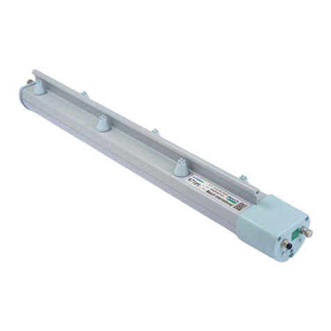
Bar length (mm)
Sensor
Power cable
Electrode cartridge
Made to Order
Non-standard bar length
Model with 80 mm-pitch electrode cartridges
460, 540, 700, 860, 940, 1020, 1180, 1340, 1420, 1580, 1660, 1740, 1820, 1980, 2060, 2140, 2220
The main unit is shipped fitted with an electrode cartridge security cover
available as an option.
This model comes fitted with electrode cartridges arranged at a 40 mm-pitch. (Standard pitch: 80 mm)
Note) Maximum bar length is 1260 mm. The air purge nozzles are arranged at an 80 mm-pitch.
A short type ionizer (full length of 180 mm and 220 mm) can be installed in a small space.
The high-voltage unit (ionizing unit) and control unit are detachable from each other.
The distance between them is also optional according to the length of the selected
connection cables.
Model with electrode cartridge security cover
Model with 40 mm-pitch electrode cartridges
High-voltage/control unit detachable short type
Model with 80 mm-pitch electrode cartridges
High-voltage/control unit detachable short type
Model with 40 mm-pitch electrode cartridges
X10
X14
X15
X210
X211
Variations
Bracket
3 m,10 m
Ionizer / Series IZS31
Contents SpecificationsSymbol
Non-standard power cable length
Available in 1 m increments from 1 m to 20 m
X13
Power cable
Ionizer driving AC adapter
Input voltage: 100 V to 240 V, Output voltage: 24 VDC
X196EU
AC adapter
NewNew
NewNew
NewNew
End bracket
Electrode cartridge with rapid
elimination of static electricity
Electrode needle material
• Tungsten
• Silicon
• Stainless steel
Electrode needle material
• Tungsten
• Silicon
Electrode cartridge
with low maintenance
Feedback sensor
300, 380, 620, 780, 1100, 1260, 1500,
1900, 2300
Autobalance sensor
[High-precision type]
Autobalance sensor
[Body-mounting type]
Center bracket
End bracket Center bracket
Autobalance sensor
[Body-mounting type]
Application Examples
Eliminating static electricity on PET bottles
• Trip-resistance during conveying
• Prevents adhesion of dust.
Eliminating static electricity on PET bottles
Eliminating static electricity on molded goods
• Improves detachability of molded goods from a die.
Eliminating static electricity during wafer transferEliminating static electricity during wafer transfer
•
Prevents breakage due to discharge between wafers and hands.
Eliminating static electricity from packing films
Eliminating static electricity on a film
• Prevents adhesion of dust.
• Prevents winding failure due to wrinkles, etc.
Eliminating static electricity on a film
Eliminating static electricity on film molded goods
• Prevents attaching to conveyer.
• Prevents dispersion of finished goods.
Eliminating static electricity on a glass substrate
• Prevents breakage due to adhesion and discharge.
• Prevents adhesion of dust.
Eliminating static electricity on a glass substrate
Eliminating static electricity on a electric substrate
• Prevents element disruption due to discharge.
Eliminating static electricity on an electric substrate
• Prevents adhesion of dust.
•
Prevents the filled substance from adhering to the packing film.
• Reduces packing mistakes.
Eliminating static electricity from packing films
Eliminating static electricity on film molded goods
Features 5
Bar length (mm)
Sensor
Power cable
Electrode cartridge
Made to Order
Non-standard bar length
Model with 80 mm-pitch electrode cartridges
460, 540, 700, 860, 940, 1020, 1180, 1340, 1420, 1580, 1660, 1740, 1820, 1980, 2060, 2140, 2220
The main unit is shipped fitted with an electrode cartridge security cover
available as an option.
This model comes fitted with electrode cartridges arranged at a 40 mm-pitch. (Standard pitch: 80 mm)
Note) Maximum bar length is 1260 mm. The air purge nozzles are arranged at an 80 mm-pitch.
A short type ionizer (full length of 180 mm and 220 mm) can be installed in a small space.
The high-voltage unit (ionizing unit) and control unit are detachable from each other.
The distance between them is also optional according to the length of the selected
connection cables.
Model with electrode cartridge security cover
Model with 40 mm-pitch electrode cartridges
High-voltage/control unit detachable short type
Model with 80 mm-pitch electrode cartridges
High-voltage/control unit detachable short type
Model with 40 mm-pitch electrode cartridges
X10
X14
X15
X210
X211
Variations
Bracket
3 m,10 m
Ionizer / Series IZS31
Contents SpecificationsSymbol
Non-standard power cable length
Available in 1 m increments from 1 m to 20 m
X13
Power cable
Ionizer driving AC adapter
Input voltage: 100 V to 240 V, Output voltage: 24 VDC
X196EU
AC adapter
NewNew
NewNew
NewNew
End bracket
Electrode cartridge with rapid
elimination of static electricity
Electrode needle material
• Tungsten
• Silicon
• Stainless steel
Electrode needle material
• Tungsten
• Silicon
Electrode cartridge
with low maintenance
Feedback sensor
300, 380, 620, 780, 1100, 1260, 1500,
1900, 2300
Autobalance sensor
[High-precision type]
Autobalance sensor
[Body-mounting type]
Center bracket
End bracket Center bracket
Autobalance sensor
[Body-mounting type]
Application Examples
Eliminating static electricity on PET bottles
• Trip-resistance during conveying
• Prevents adhesion of dust.
Eliminating static electricity on PET bottles
Eliminating static electricity on molded goods
• Improves detachability of molded goods from a die.
Eliminating static electricity during wafer transferEliminating static electricity during wafer transfer
•
Prevents breakage due to discharge between wafers and hands.
Eliminating static electricity from packing films
Eliminating static electricity on a film
• Prevents adhesion of dust.
• Prevents winding failure due to wrinkles, etc.
Eliminating static electricity on a film
Eliminating static electricity on film molded goods
• Prevents attaching to conveyer.
• Prevents dispersion of finished goods.
Eliminating static electricity on a glass substrate
• Prevents breakage due to adhesion and discharge.
• Prevents adhesion of dust.
Eliminating static electricity on a glass substrate
Eliminating static electricity on a electric substrate
• Prevents element disruption due to discharge.
Eliminating static electricity on an electric substrate
• Prevents adhesion of dust.
•
Prevents the filled substance from adhering to the packing film.
• Reduces packing mistakes.
Eliminating static electricity from packing films
Eliminating static electricity on film molded goods
Features 6
1) Installation distance and discharge time (Discharge time from 1000 V to 100 V)
Electrode cartridge with rapid elimination of static electricity
Air purge: Yes
Air purge: Yes
Air purge: Yes
Static Electricity
Elimination Characteristics
Series
IZS31
Technical Data 1
Air purge: No Air purge: Yes
Air purge: Yes
Air purge: Yes
Note) Static electricity elimination features are based on the data using a charged plate (size: 150 mm x 150 mm,
capacitance: 20 pF) as defined in the U.S. ANSI standards (ANSI/ESD, STM3, 1-2000). Use this as a guideline
for model selection because the value varies depending on the material and/or size of a subject.
Supply pressure: 0.05 MPa (3.5 l/min (ANR) per nozzle)
45
40
35
30
25
20
15
10
5
0
0 500 1500 2000
Discharge time (sec)
With sensor
1 Hz
60 Hz
45
40
35
30
25
20
15
10
5
00 500 1000 1500 2000
Installation distance (mm)
Discharge time (sec)
1 Hz
25
20
15
10
5
00 500 1000 1500 2000
Installation distance (mm)
1000
Installation distance (mm)
Discharge time (sec)
1 Hz/60 Hz
20
15
10
5
00 500 1000 1500 2000
Installation distance (mm)
Discharge time (sec)
1 Hz/60 Hz
Discharge time (sec)
Installation distance (mm)
60 Hz 30 Hz
15 Hz 5 Hz
1 Hz
30
25
20
15
10
5
00 100 200 300 400 500 600
With sensor
1 Hz
/
60 Hz
Installation height of the sensor: 10 mm Installation height of the sensor: 10 mm
Installation height of the sensor: 10 mm
60 Hz
With sensor
0
15
10
5
0500 1000 1500 2000
Installation distance (mm)
Discharge time (sec)
1 Hz/60 Hz
15
10
5
00500 1000 1500 2000
Installation distance (mm)
Discharge time (sec)
1 Hz/60 Hz
With sensor
Installation height of the sensor: 10 mm
With sensor
Installation height of the sensor: 10 mm
With sensor
With sensor
Supply pressure: 0.1 MPa (7 l/min (ANR) per nozzle)
Supply pressure: 0.5 MPa (20 l/min (ANR) per nozzle) Supply pressure: 0.3 MPa (14 l/min (ANR) per nozzle)
Supply pressure: 0.7 MPa (30 l/min (ANR) per nozzle)
Supply pressure: 0.02 MPa (1 l/min (ANR) per nozzle)
Installation height of the sensor: 10 mm
45
40
35
30
25
20
15
10
5
0
0 500 1000 1500 2000
With sensor
1 Hz
60 Hz
45
40
35
30
25
20
15
10
5
0
0 500 1000 1500 2000
With sensor
1 Hz
60 Hz
25
20
15
10
5
00 500 1000 1500 2000
With sensor
1 Hz/60 Hz
20
15
10
5
0
0 500 1000 1500 2000
With sensor
1 Hz/60 Hz
Installation height of the sensor: 10 mm
Discharge time (sec)
Installation distance (mm)
Discharge time (sec)
Installation distance (mm)
Discharge time (sec)
Installation distance (mm)
Discharge time (sec)
Supply pressure: 0.1 MPa (7 l /min (ANR) per nozzle)
Supply pressure: 0.02 MPa (1 l /min (ANR) per nozzle)
Air purge: Yes
Supply pressure: 0.05 MPa (3.5 l /min (ANR) per nozzle)
Air purge: Yes
Supply pressure: 0.3 MPa (14 l /min (ANR) per nozzle)
Air purge: Yes
Electrode cartridge with low maintenance
Air purge: Yes
15
10
5
0
0 500 1000 1500 2000
With sensor
1 Hz/60 Hz
15
10
5
0
0 500 1000 1500 2000
1 Hz/60 Hz
With sensor
Installation distance (mm)
Discharge time (sec)
Installation distance (mm)
Discharge time (sec)
Supply pressure: 0.5 MPa (20 l /min (ANR) per nozzle)
Air purge: Yes
Supply pressure: 0.7 MPa (30 l /min (ANR) per nozzle)
Air purge: Yes
Be sure to perform air purge when using a low-
maintenance electrode cartridge.
Without air purge, low-maintenance efficiency will
decrease.
Caution
Technical Data
1
1) Installation distance and discharge time (Discharge time from 1000 V to 100 V)
Electrode cartridge with rapid elimination of static electricity
Air purge: Yes
Air purge: Yes
Air purge: Yes
Static Electricity
Elimination Characteristics
Series
IZS31
Technical Data 1
Air purge: No Air purge: Yes
Air purge: Yes
Air purge: Yes
Note) Static electricity elimination features are based on the data using a charged plate (size: 150 mm x 150 mm,
capacitance: 20 pF) as defined in the U.S. ANSI standards (ANSI/ESD, STM3, 1-2000). Use this as a guideline
for model selection because the value varies depending on the material and/or size of a subject.
Supply pressure: 0.05 MPa (3.5 l/min (ANR) per nozzle)
45
40
35
30
25
20
15
10
5
0
0 500 1500 2000
Discharge time (sec)
With sensor
1 Hz
60 Hz
45
40
35
30
25
20
15
10
5
00 500 1000 1500 2000
Installation distance (mm)
Discharge time (sec)
1 Hz
25
20
15
10
5
00 500 1000 1500 2000
Installation distance (mm)
1000
Installation distance (mm)
Discharge time (sec)
1 Hz/60 Hz
20
15
10
5
00 500 1000 1500 2000
Installation distance (mm)
Discharge time (sec)
1 Hz/60 Hz
Discharge time (sec)
Installation distance (mm)
60 Hz 30 Hz
15 Hz 5 Hz
1 Hz
30
25
20
15
10
5
00 100 200 300 400 500 600
With sensor
1 Hz
/
60 Hz
Installation height of the sensor: 10 mm Installation height of the sensor: 10 mm
Installation height of the sensor: 10 mm
60 Hz
With sensor
0
15
10
5
0500 1000 1500 2000
Installation distance (mm)
Discharge time (sec)
1 Hz/60 Hz
15
10
5
00500 1000 1500 2000
Installation distance (mm)
Discharge time (sec)
1 Hz/60 Hz
With sensor
Installation height of the sensor: 10 mm
With sensor
Installation height of the sensor: 10 mm
With sensor
With sensor
Supply pressure: 0.1 MPa (7 l/min (ANR) per nozzle)
Supply pressure: 0.5 MPa (20 l/min (ANR) per nozzle) Supply pressure: 0.3 MPa (14 l/min (ANR) per nozzle)
Supply pressure: 0.7 MPa (30 l/min (ANR) per nozzle)
Supply pressure: 0.02 MPa (1 l/min (ANR) per nozzle)
Installation height of the sensor: 10 mm
45
40
35
30
25
20
15
10
5
0
0 500 1000 1500 2000
With sensor
1 Hz
60 Hz
45
40
35
30
25
20
15
10
5
0
0 500 1000 1500 2000
With sensor
1 Hz
60 Hz
25
20
15
10
5
00 500 1000 1500 2000
With sensor
1 Hz/60 Hz
20
15
10
5
0
0 500 1000 1500 2000
With sensor
1 Hz/60 Hz
Installation height of the sensor: 10 mm
Discharge time (sec)
Installation distance (mm)
Discharge time (sec)
Installation distance (mm)
Discharge time (sec)
Installation distance (mm)
Discharge time (sec)
Supply pressure: 0.1 MPa (7 l /min (ANR) per nozzle)
Supply pressure: 0.02 MPa (1 l /min (ANR) per nozzle)
Air purge: Yes
Supply pressure: 0.05 MPa (3.5 l /min (ANR) per nozzle)
Air purge: Yes
Supply pressure: 0.3 MPa (14 l /min (ANR) per nozzle)
Air purge: Yes
Electrode cartridge with low maintenance
Air purge: Yes
15
10
5
0
0 500 1000 1500 2000
With sensor
1 Hz/60 Hz
15
10
5
0
0 500 1000 1500 2000
1 Hz/60 Hz
With sensor
Installation distance (mm)
Discharge time (sec)
Installation distance (mm)
Discharge time (sec)
Supply pressure: 0.5 MPa (20 l /min (ANR) per nozzle)
Air purge: Yes
Supply pressure: 0.7 MPa (30 l /min (ANR) per nozzle)
Air purge: Yes
Be sure to perform air purge when using a low-
maintenance electrode cartridge.
Without air purge, low-maintenance efficiency will
decrease.
Caution
Technical Data
2
Charged plate
Feedback sensor
Ionizer
600 mm
Installation height of the feedback sensor
Electrode cartridge with rapid elimination of static electricity
Air purge: No
Horizontal distance to the ionizer - Charged object location (mm)
Front/Rear distance to the ionizer - Charged object location (mm)
100 mm
100 mm
Height 100 mm
Height 300 mm
Height 500 mm
Ion balance (V)
Installation height of the feedback sensor (mm)
90
60
30
0
–30
–60
–90
0 100 200 300 400 500
Catalog specification value: ±30 V
Air purge: Yes (0.1 MPa)
Discharge time (sec)
Installation height of the feedback sensor (mm)
8
7
6
5
4
3
2
1
00 100 200 300 400 500
Discharge time from 1000 V to 100 V
Without sensor
With feedback sensor
2) Static electricity elimination range
Series
IZS31
Technical Data 2
3) Installation height of the feedback sensor and discharge time / Ion balance
The height a feedback sensor is mounted at should be 50 mm or less. When using a feedback sensor at a height greater than 50 mm, refer to the below graphs.
Electrode cartridge with rapid elimination of static electricity, electrode cartridge with low maintenance
Air purge: Yes (0.05 MPa to 0.7 MPa)
Horizontal distance to the ionizer - Charged object location (mm)
Front/Rear distance to the ionizer - Charged object location (mm)
100 mm
100 mm
Height 500 mm
Height 1000 mm
Height 1500 mm
Height 2000 mm
Note) Static electricity elimination features are based on the data using a charged plate (size: 150 mm x 150 mm,
capacitance: 20 pF) as defined in the U.S. ANSI standards (ANSI/ESD, STM3, 1-2000). Use this as a guideline
for model selection because the value varies depending on the material and/or size of a subject.
Static Electricity
Elimination Characteristics
Sensor head
Detection hole
Sensor head
Detection
hole
Detection range
Installation distance
45
100
180
10
25
50
Feedback sensor detection range
The relationship between the installation distance of the
electrostatic sensor and the detection range is as follows:
How to measure
0.7
0.6
0.5
0.4
0.3
0.2
0.1
0
Supply pressure (MPa)
Flow rate (l/min)(ANR)
0 50 100 150 200 250 300
300 380 620 780
1900
2300
(a) Single side air supply
(IZS31-300, 380, 620, 780)
Air supply measurement Pressure measurement
TU0425: Length 10 mm
KQ2T04-00
TU0425: Length 10 mm
KQ2T04-00 KQ2T04-00
(b) Both sides air supply
(IZS31-1100, 1260, 1500, 1900, 2300)
-2000 -1500 -1000 -500 0 500 1000 1500 2000
Electrostatic potential (V)
0
1
2
3
4
5
6
Relationship in installation distance between
electrostatic potential and sensor output voltage
Sensor output voltage (V)
Installation distance 10 mm
Installation distance 25 mm
Installation distance 50 mm
4) Flow rate — Pressure characteristics
Sensor Monitor Output (When a feedback sensor is used)
Series
IZS31
Technical Data 3
1100
1260
1500
Note) Static electricity elimination features are based on the data using a charged plate (size: 150 mm x 150 mm,
capacitance: 20 pF) as defined in the U.S. ANSI standards (ANSI/ESD, STM3, 1-2000). Use this as a guideline
for model selection because the value varies depending on the material and/or size of a subject.
Note) The installation distance in the figure refers to the distance from the target
to the electrostatic sensor.
Installation
distance (mm)
Detection
range (mm)
Static Electricity
Elimination Characteristics
3