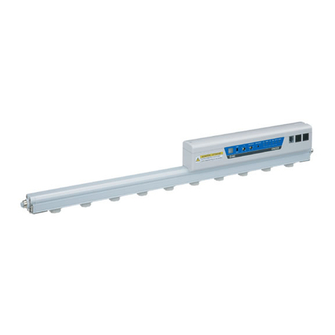
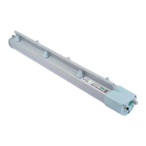
SMC Networks IZN10E Series Instruction manual

p. 4,21
p. 5,23
Dust removal and static neutralization by air blow
Static neutralization and particle
elimination on plastic bottles
Spot type static neutralization
· Prevents electrostatic breakdown
of electric parts.
· Prevents detachment failure.
Nozzle Type Ionizer
33%reduction
120 g a80 g
Slim
Lightweight
16 mm x100 mm x46 mm
Thickness
Width Height
Circular diffusion
nozzle
High flow rate
nozzle
Energy saving static
neutralization
nozzle
With right angles -X367
Nozzle Variations Made to order Application Examples
Circumferential jet bar nozzle
(straight type)
Flat diffusion
nozzle
Bender tube nozzle
Bar nozzle
(straight type)
Long nozzle
Offset voltage: ±10 V
(For energy saving static neutralization nozzle)
16 mm
46
mm
100
mm
Female threads
for piping
High flow
rate nozzle
Energy saving static
neutralization nozzle
RoHS
®
IZN10E Series
CAT.ES100-121A

Compressed air
for assisting
Ionized air
Compressed air for transferring ions
External air inlet
External air inlet
External air
Compressed air
Compressed air
External air
Ionized air
Compressed air
for assisting
Ionized air
Compressed air for transferring ions
External air inlet
External air inlet
External air
Compressed air
Compressed air
External air
Ionized air
Nozzle Type Ionizer IZN10E Series
Nozzle type can be selected according to applications.
Discharge time reduced by
65
%
Neutralizing static electricity from an elec-
tric substrate
· Prevents electrostatic
breakdown of electric
parts.
·
Removes dust from lens.
·
Prevents adhesion of dust.
·
Prevents static elec-
tricity charging when
opening bags.
·
Prevents static elec-
tricity cling on the in-
side of candy bags.
¡
Improved dust removal
performance
¡
Long range static neutrali-
zation: Max. 500 mm
¡Offset voltage: ±15 V
·
Prevents problems
with the separation
of molded plastic
goods.
· Removes dust cling-
ing to cup interiors.
· Prevents clogging of parts feeder.
2.0 s
6 s
2.5 m/s
With external
air inlet
Nozzle
Nozzle External air inlet
With external
air inlet
Without external
air inlet
Without external
air inlet 1.0 m/s
<Static neutralization is possible with
minimal air consumption.>
Ionized air flow velocity
improved by
2.5
times or more
Neutralizing static electricity from lens Neutralizing static electricity from packing
films
Short range static neutralization
Long range static neutralization
Neutralizing static electricity from molded
goods
Neutralizing static electricity from plastic
cups
Neutralizing static electricity from parts
feeder
<Ionized air assisted by the compressed air>
Conditions
Supply pressure: 0.3 MPa, Distance: 300 mm, Air consumption flow rate: 10 L/min (ANR)
Design focuses on
offset voltage
Offset voltage: ±10 V
Energy saving static neutralization nozzle
High flow rate nozzle
1

Compressed air
Abnormal
pressure
occurrence
Stop
Abnormal
pressure
detection
Pressure switch
Ionizer Stop
Charged
potential
measurement
Static
neutralization
completed
Electrostatic
sensor monitor
Ionizer
Compressed air
Abnormal
pressure
occurrence
Stop
Abnormal
pressure
detection
Pressure switch
Ionizer Stop
Charged
potential
measurement
Static
neutralization
completed
Electrostatic
sensor monitor
Ionizer
Nozzle Type Ionizer IZN10E Series
With external switch input function (2 inputs)
High voltage power supply cable is not necessary.
A high voltage power supply is built in, therefore an external high voltage power supply or high voltage
power supply cable is not required.
Prevents
static neutralization trouble
Energy saving
Easy maintenance
¡
Can be disassembled into 3 parts.
Tools are unnecessary for the installation
or removal of the assembly.
¡Possible to conduct mainte-
nance on the emitter without
removal of body.
¡No need to readjust the nozzle
angle when the ionizer is re-
started.
Maintenance warning
function
Monitors emitter contamination or
wear continuously and will turn on
an LEDs and output signal.
Detects optimal maintenance time,
reduced labor for maintenance.
ISE20IZN10E IZN10E IZD10 IZE11
Emission of static electricity is suspended when
abnormal purge air pressure is detected by pressure
switch.
Emission of static electricity is suspended when an
electrostatic sensor detects that static neutralization is
completed.
qEmitter
assembly p. 12
eCartridge assembly p. 12
wBody assembly p. 12
2

2-port solenoid valveIonizer
Air purge
Intermittent control timer
Nozzle Type Ionizer IZN10E Series
Intermittent control timer Related product
Air saving
IZE110-X238
A digital timer that can control ON/OFF
switches of valves etc.
Intermittent ion discharge
reduces air consumption.
Mounting variations
VDirect mount
Top through-hole mounting
L-bracket Pivoting bracket
(Mounting angle adjustable range)
40°
(Mounting angle adjustable range)
30°
30°
Single unit
Manifold
DIN rail mounting bracket
35°
Bottom tapped mounting
VBracket mount p. 12
· The L-bracket and the DIN rail mounting bracket can be used with the manifold.
p. 20
Mounting surface
90°
3

Static neutralization from narrow conveyor space
360° rotation
External air inlet
Ionized air
Compressed air
External air
External air
External air
inlet
Compressed air
for assisting
Ionized air
Air for transferring ions
Compressed air
Nozzle Type Ionizer IZN10E Series
With right angles -X367
2 types of nozzles
Short range static neutralization
Design focuses on offset voltage.
Offset voltage: Within ±10 V*1
Increases air blow flow rate by
external air intake
Static neutralization is possible
with minimal air consumption.
Obstacle at upper portion
of equipment
Long range static neutralization
and dust removal
Ionized air assisted by
the compressed air
¡
Improved dust removal performance by
the energy of compressed air.
¡
Suitable for static neutralization
at a long distance (max. 500 mm).
Offset voltage: Within ±30 V*1
Energy saving static neutralization nozzle
High flow rate nozzle
*1 Installation distance: 100 mm
Nozzle variations Made to order p. 21
4

Static neutralization range
Ionized air
Static neutralization range
Ionized air
Nozzle Type Ionizer IZN10E Series
Nozzle variations Made to order
Circular diffusion nozzle
Circumferential jet bar nozzle (straight type)
Flat diffusion nozzle
Bender tube nozzle
Bar nozzle (straight type)
Long nozzle
For the ionizer, please select the female threads for piping (Rc1/8).
p. 23
5

Nozzle type
Ion generation
method Corona discharge type
Input/Output
specifications NPN, PNP
Bracket
Options
Related product
Made to order
Nozzle Type Ionizer IZN10E Series
Series Variations
IZN10E-01 IZN10E-02 IZN10E-11
Nozzle variations
Energy saving
static neutraliza-
tion nozzle
High flow
rate nozzle
Female
threads
for piping
Intermittent control timer
p. 20
p. 13
p. 12
Fixed mounting
Pivot mounting
Manifold
L-bracket
AC adapter
Pivoting bracket
Circular diffusion
nozzle
Energy saving
static neutralization nozzle
with right angles
High flow rate nozzle
with right angles
Flat diffusion
nozzle
Bar nozzle
(straight type)
Circumferential jet bar nozzle
(straight type)
Bender tube nozzle Long nozzle
Manifold mounting parts set
DIN rail mounting bracket
Cleaning kit
Related product Made to order
6

Technical Data
Static Neutralization Characteristics p. 8
Blow Velocity Distribution p. 8
Flow Rate Characteristics p. 9
Ozone Concentration p. 9
How to Order p. 10
Specifications p. 11
Accessories p. 12
Repair Parts p. 12
Options p. 13
Functions p. 14
Wiring p. 15
Power Supply Cable Connection Circuit p. 16
Timing Chart p. 16
Dimensions p. 17
Related Product
Intermittent Control Timer p. 20
Made to Order
With Right Angles -X367 p. 21
Nozzle Variations p. 23
Specific Product Precautions p. 24
Safety Instructions Back Cover
Nozzle Type Ionizer
IZN10E Series
CONTENTS
Energy saving static neutralization nozzle
High flow rate nozzle
Female threads for piping
7

0 400 500200 300100
5
4
3
2
1
0
Discharge time [s]
Distance [mm]
0.05 MPa 0.1 MPa
0.3 MPa
0.5 MPa 0.7 MPa
0 400 500200 300100
5
4
3
2
1
0
Discharge time [s]
Distance [mm]
0.05 MPa
0.1 MPa
0.3 MPa
0.7 MPa0.5 MPa
0 400 500200 300100
5
4
3
2
1
0
Discharge time [s]
∗Maximum operating pressure is 0.1 MPa.∗1
Tube length [mm]
0.05 MPa
0.1 MPa
0 400 500200 300100
5
4
3
2
1
0
Discharge time [s]
∗Maximum operating pressure is 0.3 MPa.∗1
Tube length [mm]
0.05 MPa
0.1 MPa
0.3 MPa
Distance [mm]
Distance (Horizontal) [mm]
0
100
200
300
400
500 30−30 −20 −10 0 10 20
4 m/s
2 m/s
3 m/s
Distance [mm]
Distance (Horizontal) [mm]
0
100
200
300
400
500
30−30 −20 −10 0 10 20
14 m/s
8 m/s
11 m/s
Static Neutralization Characteristics (Discharge Time from +1000 V to +100 V)
*1 Refer to “Cautions when using the IZN10E-11mmm-mfemale threads for piping” on page 10.
*2 The ionizer generates a small amount of ozone. Please use ozone resistant tubing and fittings for piping the female threads. Check periodically for ozone
deterioration, and replace if necessary.
q
Energy saving static neutralization nozzle IZN10E-01
wHigh flow rate nozzle IZN10E-02
eFemale threads for piping IZN10E-11 With Stainless steel 316 One-touch fitting*2+ Anti-static tubing
Tube I.D.: 4 mm
*Discharge time at a distance of 50 mm from the end of tube
Tube I.D.: 5 mm
*Static neutralization characteristics are based on data using a charged
plate (dimensions: 150 mm x 150 mm, capacitance: 20 pF) as defined
in the U.S. ANSI standards (ANSI/ESD STM3.1-2006). Use this as a
guideline purpose only for model selection because the value varies
depending on the material and/or size of a subject.
IZN10E Series
Technical Data
Blow Velocity Distribution (Supply Pressure: 0.3 MPa)
q
Energy saving static neutralization nozzle IZN10E-01
wHigh flow rate nozzle IZN10E-02
8

0 20 2510 155
0.7
0.6
0.5
0.4
0.3
0.2
0.1
0
Supply pressure [MPa]
Flow rate [L/min (ANR)]
0 200100 15050
0.7
0.6
0.5
0.4
0.3
0.2
0.1
0
Supply pressure [MPa]
Flow rate [L/min (ANR)]
0 300100 200
0.30
0.25
0.20
0.15
0.10
0.05
0.00
Supply pressure [MPa]
Flow rate [L/min (ANR)]
O.D. 6 mm, I.D. 4 mm,
Length 500 mm
O.D. 6 mm, I.D. 4 mm,
Length 500 mm
O.D. 8 mm, I.D. 5 mm,
Length 100 mm to 500 mm
O.D. 8 mm, I.D. 5 mm,
Length 100 mm to 500 mm
O.D. 6 mm, I.D. 4 mm,
Length 100 mm
O.D. 6 mm, I.D. 4 mm,
Length 100 mm
0 0.4 0.60.2
0.03
0.02
0.01
0.00
Concentration [ppm]
Supply pressure [MPa]
0 0.4 0.60.2
0.03
0.02
0.01
0.00
Concentration [ppm]
Supply pressure [MPa]
O.D. 6 mm, I.D. 4 mm tube
(Length 10 mm)
ø6 Union tee fitting
Ionizer
Flow meter
Pressure gauge
Ionizer
Ozone monitor
300
Flow Rate Characteristics
e
Female threads for piping IZN10E-11
With Stainless steel 316 One-touch fitting + Anti-static tubing
*When a pressure above each line is used, the maintenance warning
function may work and turn on the LED. Refer to “Cautions when using
the IZN10E-11mmm-mfemale threads for piping” on page 10.
q
Energy saving static neutralization nozzle IZN10E-01
wHigh flow rate nozzle IZN10E-02
Fig. 1: Flow rate characteristics measuring circuit
Ozone Concentration
Fig. 2: Ozone condensation measuring circuit
*Ozone condensation can increase in an enclosed space. Check the ozone condensation of the operating environment before use.
q
Energy saving static neutralization nozzle IZN10E-01
wHigh flow rate nozzle IZN10E-02
9
IZN10E Series

Nozzle, Fitting
Ionized air
Emitter periphery
Emitter
Female threads for piping Compressed air
How to Order
01 PIZN10E 06 Z B1
High frequency AC nozzle type
Nozzle type
Symbol Type
01 Energy saving static neutralization nozzle
02 High flow rate nozzle
11 Female threads for piping*1
*1 Refer to the cautions when using the female threads for
piping shown below.
Input/Output specifications
Symbol Type
Nil NPN input/output
PPNP input/output
Power supply cable
Symbol Type Part no.
Nil With power supply cable (3 m) IZN10E-CP
ZWith power supply cable (10 m) IZN10E-CPZ
NWithout power supply cable —
*Mounting is interchangeable with the current model (IZN10).
Port size (One-touch fitting)
Symbol Type
06 ø6: Metric size
One-touch
fitting
07 ø6.35 (1/4"): Inch size
16 ø6: Metric size (Elbow)
One-touch
fitting
17 ø6.35 (1/4"): Inch size (Elbow)
Bracket
Symbol Type Part no.
Nil None —
B1 L-bracket IZN10-B1
B2 Pivoting bracket IZN10-B2
B3 DIN rail mounting bracket IZN10-B3
*Refer to page 12. Brackets are the same as those for the
current model (IZN10). Mounting is interchangeable.
Cautions when using the IZN10E-11mmm-mfemale threads for piping
Sectional view of the female threads for piping
· For the female thread (Rc1/8) type, a custom made nozzle or fittings/tubing
combination must be prepared and connected by the user.
·
If a nozzle with discharge port diameter or tubing with an I.D. of less than 4 mm is
connected, the air pressure inside the nozzle may increase depending on the configuration.
·
This product uses a high frequency AC voltage. If the air pressure around the emitter
increases during ion generation, the ion generation efficiency decreases and the maintenance
alarm (signal output, maintenance LED) will be activated (refer to the figure to the right).
·
When the maintenance alarm is generated, the static neutralization performance is decreased.
· The table below shows the supply pressure specifications when made-to-order
nozzles and fittings/tubing combinations are connected.
· When using piping materials prepared by the user, secure an air passage of 4 mm or more inside diameter. If using tubing, ensure the minimum bending radius is
used and keep the tube length to 500 mm or less.
· Please install so as not to receive a moment force on the nozzle (page 25).
Made-to-order nozzle product names/Piping examples Made-to-order nozzle part no. (page 23) Supply pressure specifications
Circular diffusion nozzle IZN10-G-X198 0.05 to 0.1 MPa
Flat diffusion nozzle IZN10-G-X199 0.05 to 0.1 MPa
Bar nozzle (straight type) IZN10-G-m-X216 0.05 to 0.1 MPa
Circumferential jet bar nozzle (straight type) IZN10-G-X278 0.05 to 0.15 MPa
Bender tube nozzle IZN10-G-m-X205 0.05 to 0.15 MPa
Long nozzle IZN10-G-m-X226 0.05 to 0.15 MPa
Fitting (Applicable tubing O.D. 6 mm) + Tube (O.D. 6 mm, I.D. 4 mm)*1— 0.05 to 0.1 MPa
Fitting (Applicable tubing O.D. 8 mm) + Tube (O.D. 8 mm, I.D. 5 mm)*1— 0.05 to 0.3 MPa
*1 When connecting the tubing, use a length of tubing 500 mm or less for the connection, regardless of the inside diameter size.
Nozzle Type Ionizer
IZN10E Series
Energy saving
static
neutralization
nozzle
High flow
rate nozzle
Female threads
for piping
Made to Order
(For details, refer to page 21.)
Symbol Specifications
-X367 Nozzle with right angles
®
10

Specifications
Model IZN10E-m
(NPN specification)
IZN10E-mP
(PNP specification)
Ion generation method Corona discharge type
Method of applying voltage High frequency AC type
Applied voltage*12.5 kVAC
Offset voltage
(Ion balance)*2
Energy saving static neutralization nozzle
±10 V
High flow rate nozzle ±15 V
Air purge
Fluid Air (Clean dry air)
Operating pressure*3*40.05 MPa to 0.7 MPa
Connecting tube size ø6, ø1/4 inch
Power supply voltage 24 VDC ±10%
Current consumption 80 mA or less
Input signal
Discharge stop signal
Connected to 0 V
Voltage range: 5 VDC or less
Current consumption: 5 mA or less
Connected to +24 V
Voltage range: 19 VDC to power supply
voltage
Current consumption: 5 mA or less
Reset signal
External switch signal 1
External switch signal 2
Output signal
Discharge signal Max. load current: 40 mA
Residual voltage: 1 V or less
(Load current at 40 mA)
Max. applied voltage: 26.4 VDC
Max. load current: 40 mA
Residual voltage: 1 V or less
(Load current at 40 mA)
Error signal
Maintenance signal
Effective static neutralization range*520 to 500 mm
Ambient temperature (Operating/Stored) 0 to 55°C
Ambient humidity (Operating/Stored) 35 to 65% RH (No condensation)
Material
Housing ABS, Stainless steel
Nozzle Stainless steel
Emitter Tungsten
Impact resistance 100 m/s2
Body weight
Energy saving static neutralization nozzle
70 g
High flow rate nozzle 70 g
Female threads for piping 75 g
Bracket weight
L-bracket 30 g
Pivoting bracket 40 g
DIN rail mounting bracket (Single unit) 40 g
Standards/Directive CE, UL, CSA, RoHS
*1 Measured with a probe of 1000 MΩand 5 pF.
*2 Measurement values based on a charged plate (dimensions: 150 mm x 150 mm, capacitance: 20 pF) defined by ANSI standard (ANSI/ESD STM3.1-2006).
The distance between the charged plate and the ionizer: 100 mm, the air purge is 0.3 MPa (energy saving static neutralization nozzle) / 0.1 MPa (high
flow rate nozzle).
*3 Static electricity cannot be neutralized without air purge. As the concentration of ozone inside the nozzle increases, there is a possibility that the product
and surrounding equipment may be adversely affected, so be sure to air purge during ion generation.
*4 To stop the air purge temporarily during operation, turn the discharge stop signal input OFF to prevent the increase of ozone concentration inside the
nozzle.
*5 Except female threads for piping.
*Refer to the cautions on page 10 when using the IZN10E-11 (female threads for piping).
Model IZN10E-Cm-m
Input voltage*1100 to 240 VAC, 50/60 Hz
Output voltage 24 VDC
Output current 1 A max
Ambient
temperature
Operating 0 to 40°C
Stored −20 to 60°C
Ambient humidity Operating/Stored 10 to 90%RH
Standards/Directive CE, cUL
*1 For the AC cord type, note that the rated voltage of the AC cord included as an accessory is 125 V (See page 13).
11
IZN10E Series
A

Accessories
Bracket
Fixed mounting Pivot mounting
Single
unit
*1 The L-bracket and the DIN rail mounting bracket can be used with the manifold.
Manifold*1
Repair Parts
L-bracket
IZN10-B1
Power supply cable
Pivoting bracket
IZN10-B2
DIN rail mounting bracket
IZN10-B3
Emitter assembly
IZN10E-NT
Nozzle type
Symbol
Type
01
Energy saving static neutralization nozzle
02 High flow rate nozzle
11 Female threads for piping
Input/Output specifications
Symbol Type
Nil NPN input/output
PPNP input/output
One-touch fitting
Symbol Type
06 ø6: Metric size
07 ø6.35 (1/4"): Inch size
16 ø6: Metric size (Elbow)
17 ø6.35 (1/4"): Inch size (Elbow)
Body assembly
Cartridge assembly
IZN10 B1 IZN10E CP
Power supply cable: Made to order
IZN10E CP X1301
IZN10E
IZN10E
A002
A003
0601
Power supply cable
Symbol Type
Nil 3 m
Z10 m
Bracket
Symbol Type
B1 L-bracket
B2 Pivoting bracket
B3 DIN rail mounting bracket
Power supply cable length
Symbol Type
01 1 m
…
…
20 20 m
*Available in 1 m increments from 1 m to
20 m.
Use standard power supply cables for 3
m and 10 m lengths.
Emitter assembly
12
Nozzle Type Ionizer IZN10E Series

28 44
962144±105 1820
Hexagon socket head
cap screw
Ionizer∗1
(Order it separately.)
Bracket∗1
(Order it separately.)
Hexagon nut
Spacer (5 mm)
L2
L1
17.49.6
Options
Manifold mounting parts set AC adapter
Cleaning kit IZS30-M2
This set consists of a hexagon socket head cap screw, spacer,
and hexagon nut.
*1 The ionizer, L-bracket, and DIN rail mounting bracket need to be prepared
separately.
*1 AC cord is only for use in Japan. (Rated voltage 125 V, Plug JIS C8303, Inlet
IEC60320-C8)
*2 Select the same input/output specification as the ionizer.
IZN10E ES
Mounting pitch
Symbol Pitch
ES 17.4 mm
Mounting stations
Symbol Stations
22
33
44
G1IZN10E C
Input/Output
specifications*2
Symbol Type
Nil NPN input/output
PPNP input/output
AC adapter
Symbol Type
G1 With AC cord*1
G2 Without AC cord
Part no. L1 L2 Number of spacers
IZN10E-ES2 37.8 45 4
IZN10E-ES3 55.2 60 6
IZN10E-ES4 72.6 76 8
AC adapter AC cord
4
13
IZN10E Series

Compressed air
Abnormal
pressure
occurrence
Stop
Abnormal
pressure
detection
Pressure switch
Ionizer
Stop
Charged
potential
measurement
Static
neutralization
completed
Electrostatic
sensor monitor
Ionizer
Functions
1. Maintenance warning
Constantly monitors lowered static neutralization performance due to contamination or wear of the emitter. The maintenance LED
lights up and maintenance signal is generated.
2. Signal inputs by external switch
There are 2 ports for external switch signal inputs.
Behavior of LEDs
Item PWR ION/HV NDL Note
Normal operation (with discharge stop signal on) Green Green Ions are being generated.
Normal operation (with discharge stop signal off) Green Discharge stops.
High voltage error occurred Green Red Discharge stops.
External switch signal 1 (with signal on) Green Discharge stops when the signal is
turned on.
External switch signal 2 (with signal on) Green
Maintenance warning occurred Green Green Green Discharge continues.
4. Alarm
Alarm item Description Corrective actions
High voltage error
Gives notification of the occurrence of an abnormal high voltage
discharge. The ionizer stops discharging, turns on the HV LED.
When error occurred, the signal output is turned off.
Turn off the power, solve the problem, then turn the power on
again. If the error is solved during operation, turn the reset
signal on and then off.
Maintenance warning Gives notification that emitter maintenance is necessary. The
NDL LED turns on and a maintenance output signal is turned on.
Turn off the power, clean the emitters, and turn the power on
again.
3. Description of LEDs
Example
Emission of static electricity is sus-
pended when abnormal purge air pres-
sure is detected by pressure switch.
•
Prevents static neutralization trouble due to pressure drop of compressed air.
Example
Emission of static electricity is suspend-
ed when an electrostatic sensor detects
that static neutralization is completed.
•
Energy can be saved by stopping discharge when static neutralization is completed.
No. Description LED Color Contents
qPower supply display PWR Green Lights up when the power supply is turned on.
w
Discharge/Irregular high voltage display
ION/HV Green/Red
Lights up when static electricity is discharged. (Green)/Lights up if an abnormal high voltage discharge occurs. (Red)
eMaintenance display NDL Green
Light is ON when the static neutralization performance is reduced due to contamination, wear or breakage of emitters.
qwe
14
Nozzle Type Ionizer IZN10E Series

Make sure to ground the ground terminal with a ground resistance of 100 Ωor less.
The ground terminal is used as a reference electric potential for static neutralization.
If the ground terminal is not grounded, the ionizer will not be able to achieve the optimal offset voltage (ion balance).
Ground terminal
Wiring
Provide Grounding
• Input signal
NPN: The signal is turned on when the 0 V power supply is connected, and turned off when disconnected.
PNP: The signal is turned on when the +24 VDC power supply is connected, and turned off when disconnected.
• Output signal
NPN: The output transistor is energized (by the 0 V power supply inside the ionizer) when the signal is turned on, and de-energized
when turned off.
PNP: The output transistor is energized (by the +24 VDC power supply inside the ionizer) when the signal is turned on, and
de-energized when turned off.
*1 Wiring requirement
v: Minimum wiring requirement for ionizer operation
No. Cable color Description I/O Wiring requirement*1Specifications
1Brown +24 VDC – v–
2Blue 0 V – v–
3Orange Discharge stop signal Input vWhen the signal is turned off, discharge stops.
4Pink Reset signal Input When the signal is turned on and then off, the error signal is reset.
When the signal is turned off, normal operation continues.
5White Discharge signal Output The signal stays on during discharge.
6Purple Error signal Output The signal is turned off when an error occurs.
7Yellow Maintenance signal Output The signal is turned on when maintenance is due.
8Gray External switch signal 1 Input When the signal is turned on, discharge stops.
9Light blue External switch signal 2 Input When the signal is turned on, discharge stops.
15
IZN10E Series

OUTPUT
INPUT
or
PLC
F.G.
Make sure to ground.
0 V
+24 V Power
supply
24 VDC
INPUT
OUTPUT
Internal circuit
+24 V
Ground
terminal
+24 V
Ionizer
Light blue: External switch signal 2
Gray: External switch signal 1
Yellow: Maintenance signal
Purple: Error signal
White: Discharge signal
Pink: Reset signal
Orange: Discharge stop signal
Blue 0 V
Brown + 24 VDC
+24 V
+24 V
+24 V
Make sure to ground.
or
or
or
OUTPUT
INPUT
or
PLC
F.G.
Make sure to ground.
0 V
+24 V Power
supply
24 VDC
INPUT
OUTPUT
Internal circuit
+24 V
Ground
terminal
+24 V
+24 V
+24 V
Ionizer
Light blue: External switch signal 2
Gray: External switch signal 1
Yellow: Maintenance signal
Purple: Error signal
White: Discharge signal
Pink: Reset signal
Orange: Discharge stop signal
Blue 0 V
Brown + 24 VDC
Make sure to ground.
or
or
or
Power Supply Cable Connection Circuit
Timing Chart
MNPN input/output MPNP input/output
Power supply
Discharge stop signal
Reset signal
Error signal
Maintenance signal
External switch signal 1, 2
Input
Input
Input
Output
Output
Output
Input
ON
OFF
ON
OFF
ON
OFF
ON
OFF
ON
OFF
ON
OFF
ON
OFF
Discharge signal
(on when ions are being generated)
Power supply on High voltage error
50 ms or more
50 ms or more
Maintenance required External switch on Note
The error signal can be reset by
turning the reset signal on and
then off.
Ions are still generated even
when the maintenance signal is
turned on.
When an error occurs, the signal
is turned off.
Discharge starts when the signal
is turned on.
Turn off the power supply
and clean the emitter.
Error occurred
Requirement for maintenance detected
Make sure to ground the ground terminal with a ground resistance of 100 Ωor less.
The ground terminal is used as a reference electric potential for static neutralization.
If the ground terminal is not grounded, the ionizer will not be able to achieve the optimal offset voltage (ion balance).
16
Nozzle Type Ionizer IZN10E Series

2 x M3 x 0.5 thread depth 10
Applicable tubing O.D. ød
18.3∗1
29∗1
11
34.7 26
18.3∗1
16
46
6
8
L
L
M3 x 0.5 thread depth 4
(Ground terminal)
(100)
592.5
A86.4
4027.7
6
11
18.5
5
2.5
L-L
12.4
ø3.5
ø6
180°
B
C
D
Applicable tubing O.D. ød
Rc1/8
ø14
Width across
flats 12 10.6
5
Dimensions
Energy saving static neutralization nozzle IZN10E-01m
06
07
High flow rate nozzle IZN10E-02m
06
07
One-touch fitting (Elbow) IZN10E-mm
16
17
Female threads for piping (Rc1/8) IZN10E-11mm
[mm]
Model dA
IZN10E-01
02m06 6 3.5
IZN10E-01
02m07 1/4" 7
[mm]
Model dB C D
IZN10E-mm16 6 22 16 11.5
IZN10E-mm17 1/4" 24.5 18.5 12
*1 Dimension of the resin part in described in the Mounting
Warning note 3 (page 24).
17
IZN10E Series

61
21
61
33
52
20.5
(83)
30°
(Mounting angle adjustable range)
46
33
2 x M3
40
25
50
5
17
7.5
(Mounting angle
adjustable range) 40°
2 x Hexagon socket head cap
screw M3 x 6 (Accessory)
8 x ø3.4
2 x 3.4
2 x R10
2 x 3.4
26 12
40 5 22.7
17
44
11
26
30°
30°
Internal mountingPivot mounting
Internal mounting
90°
(Mounting angle adjustable range)
20
18
11.4 28
ø3.4
3.4
20
64
4
14
24
59
40
20°
9
13.7
56
2 x Hexagon socket head cap screw M3 x 16
(Accessory)
Dimensions
L-bracket IZN10-B1
Pivoting bracket IZN10-B2
18
Nozzle Type Ionizer IZN10E Series

61
20.5
55
33
50
17
(Mounting angle
adjustable range) 40°
70
21
33
70
(92)
30°
(Mounting angle adjustable range)
2 x Hexagon socket head cap
screw M3 x 6 (Accessory)
8 x ø3.4
(7.5)
40 5
1226
2 x 3.4
26
44
17
11
9
22.7
30°
30°
Internal mountingPivot mounting
Internal mounting
9
1
22
7.5 8L
60
Dimensions
DIN rail mounting bracket IZN10-B3
Power supply cable IZN10E-CPm
Cable Specifications
No. of cable wire/Size 9 cores/AWG26
Conductor
Nominal cross
section 0.15 mm2
O.D. 0.5 mm
Insulator O.D. 0.95 mm Brown, Blue, Orange, Pink,
White, Purple, Yellow, Gray, Light blue
Sheath Material Lead-free PVC
O.D. 5 mm
Model L[mm]
IZN10E-CP 3000
IZN10E-CPZ 9800
19
IZN10E Series
Other manuals for IZN10E Series
1
Table of contents
Other SMC Networks Air Ionizer manuals
SMC Networks
SMC Networks IZS42 User manual

SMC Networks
SMC Networks IZG10 User manual
SMC Networks
SMC Networks IZT41 Series User manual

SMC Networks
SMC Networks IZG10 User manual
SMC Networks
SMC Networks IZS31 Series User manual

SMC Networks
SMC Networks IZG10 User manual

SMC Networks
SMC Networks IZT43 Series User manual

SMC Networks
SMC Networks IZN10E Series User manual
SMC Networks
SMC Networks IZS31 Series User manual
SMC Networks
SMC Networks IZT43-L Series User manual