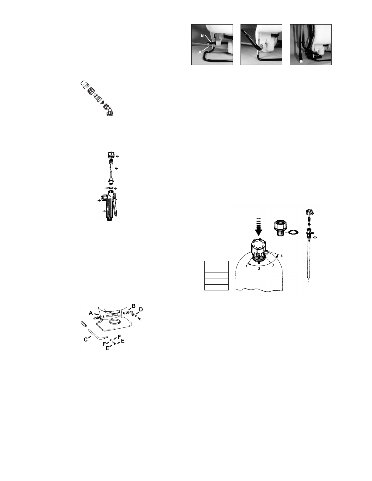
Solo 425 Classic Installation and operation manual

OPERATOR’S MANUAL & PARTS LIST 425, 475, 425D, 425LC
WARRANTY
Solo backpack sprayers are covered by Solo’s WARRANTY
(5 years for models 425 & 475, 2 years for Model 425D, 425
LC). Solo manufactured parts which fail due to defective
material or workmanship will be repaired or replaced
without charge. Refer to Warranty sections for consumer
and commercial use, of this Owners Manual, for full details.
MAINTENANCE TIP
Cap gasket is pre-lubricated for improved
sealing. Occasional lubrication is recommended.
SAFETY PRECAUTIONS
1. Before using sprayer with chemicals, fill sprayer with fresh
water to assure that you have it properly assembled;
pressurize and practice spraying.
Also, check for any leaks at this time. When thoroughly
familiar with the sprayer operation, follow normal
operating procedures.
2. Ensure all pressure in the sprayer is relieved by locking
the shut-off valve in the open position.
3. Avoid contact with chemicals.
4. Always wear rubber gloves, safety goggles and
appropriate protective clothing.
5. Work in a well ventilated area.
6. Individuals should be trained in the proper use of this
sprayer, chemical handling procedures, and first aid/
emergency care. Where training is not available,
individuals should study and follow the procedures
detailed in this manual.
If you are missing parts, instructions or have questions, DO NOT take this unit back to the store.
Call 1300 798 022. Solo will send the missing parts/information to you promptly.
STOP
Visit us on the web at www.soloaustralia.com.au Troubleshooting and parts ordering available on-line.
CUSTOMER SERVICE COMMITMENT FROM SOLO’S SERVICE DEPARTMENT: In the event the sprayer you have purchased has missing or damaged parts,
please call 1300 798 022, 9:00am – 5:00pm Mon-Fri. In order to assist your service representative, please have the following information available: sprayer model number,
part description and part number. A parts list is included in your operator’s manual. Solo is committed to your satisfaction and is continuing its efforts to earn your future business.
Chemicals can be harmful to individuals and the environment
if improperly used. In addition, some chemicals are caustic,
corrosive or poisonous and should be avoided. Read
warnings and chemical manufacturers’ instructions. Solo
high density polyethylene sprayers are fitted with Viton®
seals which are resistant to a wide variety of agricultural and
household chemicals; however, care should be exercised
to ensure that sprayer components are clean, functioning
properly, and in a good state of repair before and during use.
If in doubt about a particular chemical, check with the
manufacturer. If you suspect or observe indications that
the material may be unsafe in a Solo sprayer...STOP.
DO NOT USE OR APPLY CHEMICAL. ALWAYS WEAR
RUBBER GLOVES, GOGGLES, AND APPROPRIATE
PROTECTIVE CLOTHING!
Read and follow operating instructions:
• Donotllwith,use,orsprayammablematerials.
• Donotmodifysprayer.
• Neversprayinthedirectionofhumans,animals
or property which might be injured or damaged
by spray formula.
• Donotusedisinfectants,solventsorimpregnatingagents
unless first tested to ensure they are not harmful to the
environment or sprayer.
• Donotuseliquidswithatemperatureabove43°C.
• Wearappropriateprotectiveclothingtopreventcontact
with chemical agents.
• Rinseandcleansprayerthoroughlyafterusing.
Disposal of contaminated rinse should be in accordance
with applicable ordinances. Observe the precautionary
instructions of the chemical manufacturer.
• DO NOT USE ANY ACID (INCLUDING CITRUS), PETRO
CHEMICALS OR CAUSTIC CHEMICALS (including
bleach).
• Rememberthatasprayerwithliquidisasignicantamount
of weight (15kg per 15 litres). Use caution when bending,
leaning or walking. Bend at the knees rather than the waist.
• Duringsprayeroperation,thepressurecylinder(4400240)
containscompressedairandliquid.Compressedairand
liquidunderpressureareinherentlydangerous.Before
making adjustments on sprayers fitted with a pressure
regulating valve body (40 74 323) or control knob
(40 74 344) located on the pressure cylinder or any
other repair or inspection of any sprayer, be sure to
relieve pressure through the shut-off valve and wand.
PISTON DIAPHRAGM

REMOVING THE NOZZLE
Unscrew the nozzle cap (1) from the nozzle body (3). This is best
accomplished while the retaining nut (2) is fastened tightly to the
elbow (5). Next, unscrew the retaining nut (2). Push the nozzle
body (3) out of the retaining nut (2). The filter with gasket (4) will
come out with the body. To reinstall the nozzle, reverse the
above instructions. (Plastic adjustable nozzle used as a example.
Details of all Spray Tip Assemblies are shown on the next page)
ASSEMBLY INSTRUCTIONS FOR WAND
1. Insert wand into shut-off valve as shown.
2. Tighten the screw cap clockwise onto the shut-off valve.
PUMP LEVER INSTALLATION
(MODEL 425D
,
425LC ONLY)
All hardware necessary for pump lever installation is included
with the sprayer. The pump lever (C) should be installed as
follows: place lever handle (C) onto the shaft (A). Align bolt holes
and install the two bolts (E) and washers (F); then tighten.
To install pump lever on the opposite side, remove the stop plate
(D) and washer, install the pump lever as above. The stop plate
(D) should be mounted on the inner bolt hole with the closed end
of the stop plate pointing downward on the opposite side of the
pump shaft.
FOLD-AWAY PUMP HANDLE*
INSTALLATION (FOR 425 & 475 MODELS ONLY)
1. Remove bolt and nut (A) from pump rod (B).
2. Slide handle assembly over the pump rod and align the holes
so that the rear (elbow) portion of the handle points up and
slightly forward and away from the Solo logo. Reinstall bolt
and locknut. Pump handle can be installed on the opposite
side of the sprayer for right hand pumping. (Stop plate will
need to be relocated to the left side.)
3. The handle can be rotated to either down (pumping) or up
(storage) positions.
Note: The handle swings away from the sprayer, then up or down as desired.
The spray wand attaches to the clamps on the handle assembly for storage
(does not apply to the brass wand).
SHOULDER STRAP INSTALLATION
The top of the shoulder straps are pre-attached to the sprayer
by means of a buckle. The lower end of the straps are attached
by fastening the strap hooks to the metal frame between where
frame exits the plastic tank and makes a bend.
REGULATING THE PRESSURE
(FOR 425 & 475 MODELS ONLY)
TheSolobackpacksprayerisequippedwithabuilt-inregulator
to control output pressure. This regulator is operator adjustable.
Make adjustments prior to filling tank. To adjust the regulator,
remove the tank cap and the filter basket. Look inside the spray
tank; you will see the top of the regulator. There are 4 fingers
on the regulator knob. The finger farthest to the left is 1; to the
right is 4. They are numbered 1, 2, 3, 4. 1 = 15 psi, 2 = 30 psi, 3
= 45 psi, 4 = 60 psi. The higher the pressure, the more chemical
applied from the sprayer in a given amount of time, but the
droplets will be smaller with more drift. If the spray pressure must
be changed, excess pressure in the pressure cylinder must be
released back into the tank through the spray tube.
To adjust, push down on the knob and rotate to align the desired
number with the alignment pin. To operate the Deluxe Models at
higher than 60 psi, first release the excess pressure and then
replace the adjustment piece with the optional plug (42 00 215).
FILLING
Mix the spray formula and the proper volume of water in a
separate container. Pour the mix through the filter basket in the
tank opening. This keeps debris from entering sprayer.
Note: To fill the sprayer to its full capacity, set the pressure control valve to the
3 or 4 setting. (425 & 475 models only) Add 10 litres of spray formula mix. Pump the
sprayerhandletoprimethepumpandllthepressurecylinder.Thevolumeofliquid
informulamixtankwillappeartodecreaseasthepressurecylinderislled.Liquid
will flow through the top of the pressure regulator when the cylinder is completely full.
Add the remaining formula mix to the tank.
Remember that it’s not necessary to completely fill the sprayer
tank each time. Mix only the amount needed to get the job done.
Always read and follow manufacturer’s instructions printed on the
product label. This can save money and help prevent crop and
environmental damage.
Screw Cap
Wand
Install Wand
O-ring
Gauge Mount
Shut-off
1. Nozzle
2. Retaining Nut
3. Nozzle body
4. Filter with Gasket
5. Elbow
Setting PSI
1 15
2 30
3 45
4 60
A B
1 2 3

OPERATING FEATURES
Nozzles – Your Solo sprayer is supplied with nozzle arrangements to provide a variety of spray patterns.
Item Application Part
Flat spray nozzle Row treatment 40 742 631
Jet stream nozzle Spot & longer range 40 74 755
Jet stream nozzle and Swirl plate = hollow cone Shrubs and bushes 40 74 755
40 74 756
SPRAYING
Prime the pump with rapid pump strokes. When you feel very firm
resistance,thepressurechamberisllingwithliquid.
With repeated piston strokes, the air in the pressure chamber is
slowly compressed. By pressing the hand lever, the valve opens,
andliquidisforcedthroughthenozzle.Theshut-offvalvehasa
retaining clip which keeps the valve in the “OPEN” position for
continuous operation. Pump using the end of the pump handle,
asitislessfatiguing.Thevolumeofliquiddeliveredvarieswith
the working pressure which should be as high as needed to
ensureanadequatespraypatternforeachindividualapplication.
Note:Shouldthepressuredropveryquickly,drainthetankcompletelyandpump
withoutliquid.Bythisprocedure,theairchamberisrelledwiththerequiredvolume
of air. It is advisable to pump the tank completely empty from time to time.
SPRAY TIP ASSEMBLY
WETTABLE POWDERS & MARKER DYE
Avoid use in piston pump sprayers models 425,425D
& 425LC
.
The Solo models 475 sprayers with a diaphragm pump are
generally resistant to abrasive materials and are
recommended for this purpose.
Note: If you use a wettable powder in your 425 sprayer, be sure it is thoroughly mixed
in the formula solution.
Immediately after use, be sure to remove the piston, clean and
lubricate the Viton®collar with petroleum jelly. Thorough flushing
of sprayer will extend the life of its working parts. If you use
wettable powders in the piston pump sprayer, be sure to inspect
regularly for seepage around the piston and repair accordingly.
Flat spray Hollow Cone spray Brass
Adjustable
nozzle
Jet Stream Plastic
Adjustable
nozzle
1. Flat spray nozzle
2. Filter
3. Jet cap
4. Swirl plate
5. Nozzle cap
6. Nozzle body
7. Brass adj. nozzle*
8. Nozzle retaining nut
*The Brass Adjustable Nozzle and Plastic Adjustable Nozzle are not a standard
supply with the Solo backpack sprayer. Spray tips should be assembled as above for
desired spray pattern.
13
4
22
8 8
8
7*
22
3
8
8
6
2
5
SPRAY TIP ASSEMBLY

CLEANING
• Afterspraying,cleanthetankthoroughly.Ifsomesprayliquid
is left inside, drain tank completely.
• Pumpingcausesairtobetakeninandtheremainingliquid
tobedischarged.Pumpuntilliquidandairarecomingout
through the nozzle.
• Relltankwithafewlitresofcleanwaterandpumpthewater
out as explained above (if necessary, repeat this procedure
several times).
• IftheLanceisremoved,thepumpcanbeushedquickly.
Improper spray distribution is the result of a clogged nozzle,
which is easily removed and cleaned.
• Soapandwatermayalsobeusedtocleantank.
• Donotuseaggressivecleaningagentsorabrasives.
• Followtherecommendationsofthechemicalmanufacturer
for disposal of waste water and chemicals.
• Activatedcharcoalinliquidorotherformmaybeusedto
absorb chemicals in tanks or spills.
NOTE: When cleaning the sprayer after working with hormone weed killers, follow the
instructions of the herbicide producers. Neutralize with activated charcoal. (Example:
add 1g. of activated charcoal to 1 liter of water and leave this detergent in the tank
and the lines approximately for 24 hours.) This is very important if other chemicals
should be sprayed as the residues of the herbicide may damage susceptible plants.
Cleaning after application of products containing carbolineum, if they are not water
soluble,shouldbedonewitha5%sodalyehavingatemperatureof40°C.Rinsewith
plenty of clean water.
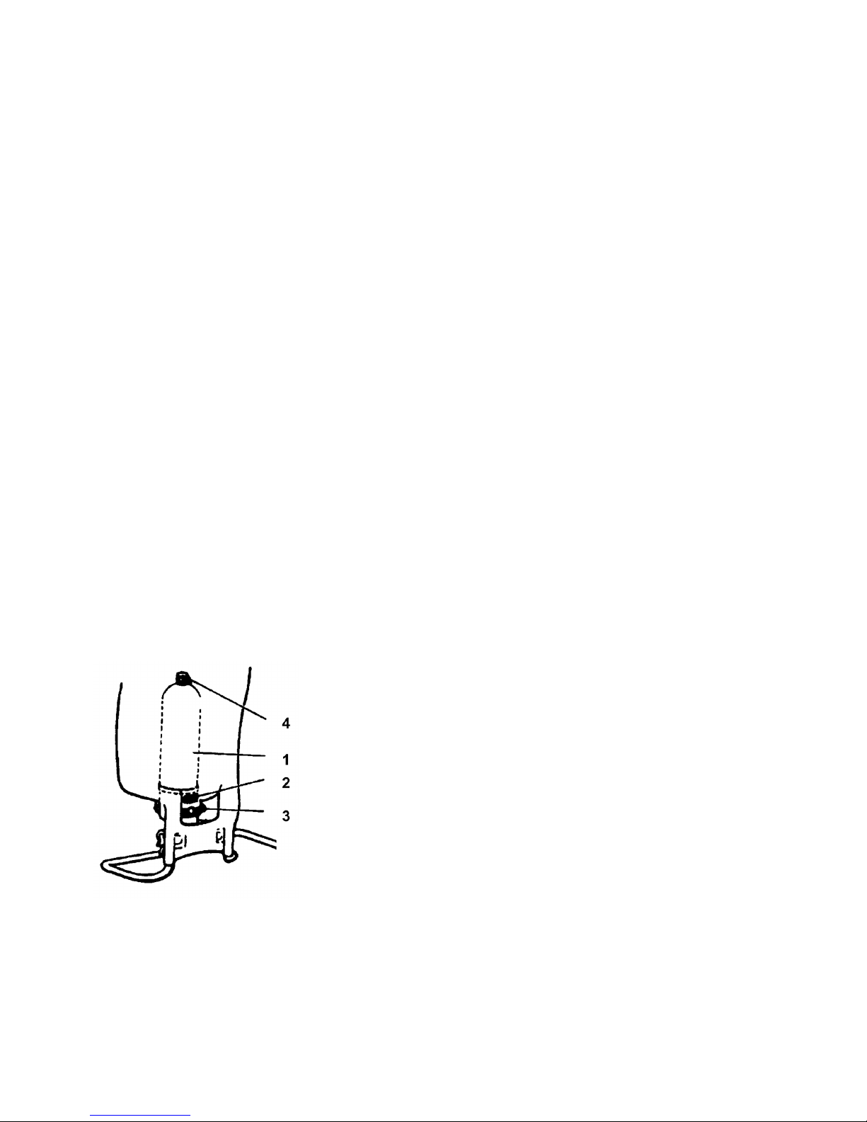
MAINTENANCE AND STORAGE TIPS
To protect the piston, cylinder and Viton®collar, a fine mesh,
stainless steel screen is located on the pressure cylinder inlet.
If you find that your sprayer will not empty the formula tank,
check for a clogged inlet screen (2). The inlet screen is located
at the bottom of the pressure cylinder on the side that faces your
back.
One indication that it needs cleaning is that when you let
go of the pump handle, it “springs” to the down position.
The screen can be cleaned with a small bristle brush or a
discarded toothbrush. See diagram for location of screen.
• Afteroperation,thesprayershouldbestoredawayfrom
direct sunlight to prevent UV damage.
• AfterremovingthepumporwhenmountinganewViton®
collar, treat both the collar and the piston with water resistant
grease.*
• Beforewinter,drainallliquidintank,linesandairchamber.
(See “Cleaning.”) Leave shut-off valve locked in the “open”
position.
• Forservice,visitourwebsitetolocateyournearest
Solo dealer. Always insist on original Solo spare parts.
• Regularlyinspecthose,wand,pump,tankandshut-offvalve
for wear, damage or leaks. Repair promptly.
• Occasionallylubricatecapgasket.*
Avoid excessive wear by:
1. Regular lubrication of Viton®collar, cylinder and piston
with water resistant grease.*
2. Prompt and thorough cleaning and flushing of sprayer.
Soap and water work well.
*Use Petroleum jelly.
SOLO WARRANTY
Solo Australia warrant the product from the date of purchase, for
a period as stated below. The warranty covers manufacturer’s
defects in material or workmanship. The warranty does not
cover malfunctions due to misuse or due to failure to follow the
instructions in this manual. Any alterations to the product are
to be performed by a Solo Australia approved service agent.
Any repairs performed by non approved personnel may void the
warranty.
To make a claim, contact Clayton Engineering, 26 French Ave,
Brendale, Q, 4500 on phone 1300 798 022 or email sales@
claytonengineering.com.au.You will be asked to provide proof
of purchase and then will be instructed on the procedure for
repairing or replacement of the product under warranty. All costs
incurred for repair or replace, and additional claims can be
discussed at this stage.
This warranty is provided in addition to other rights and remedies
you have under law: Our goods come with guarantees that
cannot be excluded under the Australian Consumer Law. You
are entitled to a replacement or refund for a major failure and
for compensation for any other reasonably foreseeable loss or
damage.You are also entitled to have the goods repaired or
replacedifthegoodsfailtobeofacceptablequalityandthe
failure does not amount to a major failure.
CONSUMER WARRANTY
Solo equipment purchased forconsumer use is covered by this
Warranty for a period of 5 years (Models 425 & 475) and 2 years
(Model 425D
& 425LC
).
COMMERCIAL WARRANTY
Solo equipment purchased for commercial use is covered by
this Warranty for a period of 2 years (Models 425 & 475) and
6 months (Model 425D
& 425LC
).
ITEMS NOT COVERED BY WARRANTY
Provisions of the Warranty will not apply to the following:
Normalservicerequirementsarisingduringthewarrantyperiod,
such as cleaning, normal wear, lubrication, filter, spray tips, etc.
Normal service work over and above the repair or replacement of
defective parts.
Any failure that results from an accident, customer abuse, normal
wear, neglect or failure to operate the product in accordance
with the instructions provided in the operator’s manual or
provided with the product. When an alteration or modification
has been performed on a Solo product, Solo is responsible
only for products as originally furnished by Solo, provided the
alterations or modifications do not adversely affect the product’s
operation, performance or durability. Parts or accessories that
are incompatible with the product are not approved by Solo.
Full disclosure of Solo’s Warranty is available from your local
Solo dealer or SOLO Australia.
1. Pressure Cylinder
2. Inlet Screen
3. Pump Clamp
4. Pressure Control Valve
(425 & 475 Models Only)

ACCESSORIES
The following accessories are not standard. Order them from your SOLO dealer.
Pressure Control Gauge (49 00 356)
Displays spraying pressure so operator can maintain desired pressure level.
Brass Adjustable Spray Nozzle (49 00 207)
Affords operator a full range of sprays from fine to jet stream.
Drift Guard (49 00 430)
Helps control application of formula under breezy conditions.
4-Nozzle Spray Boom (49 00 299)
Mounted on the back part of the sprayer frame or attached to brass spray lance with
flat spray nozzles for area treatment (total width 125cm; distance between nozzles
40.5cm).
Mounting Kit (49 00 517)
2-Nozzle Spray Boom (49 00 514)
Handheld spray boom mounts on end of spray wand (total width 84cm;
distance between nozzles 61cm). Includes 2 flat spray nozzles.
Twin Nozzle (49 00 477)
This is a multi-purpose nozzle that attaches to the end of the spray wand for double
row application.
Brass Spray Wand (49 00 528)
The spray wand is 150cm long and replaces the standard spray tube for treating
trees up to heights of 5 meters. Additional extension tube available in 50cm length
(49 00 513).
Shoulder Saver Harness (43 00 343)
Heavy duty padded straps, padded lumbar support and fully adjustable straps.
In the best interest of continued technological progress, we reserve the right to change design and configuration of any product without
prior or other notice. Therefore, please note that text and illustrations of this manual are not to be considered binding and do not
constitute a basis for legal or other claims.
Note: An order form is provided on the back pages of this manual.

111
110

DESCRIPTION
425, 475, 425D & 425LC SPARE PARTS
1 42 00 215 Plug (item 8 incl.)
2 00 10 165 Bolt
3 00 12 185 Bolt
4 00 30 131 Washer
6 00 12 185 Bolt
8 00 62 258 Gasket
9 00 62 106 O-ring
10 00 62 115 O-ring
11 00 62 291 O-ring
12 00 62 139 O-ring
13 00 62 140 O-ring
14 00 64 234 Hose
15 00 66 388 Hose clamp
16 00 66 394 Clamp
17 40 43 123 Stop plate
18 40 35 111 Pump shaft
20 40 61 257 Valve plate
21 42 00 242 25 Red tank cap (item 48, 98 & 99 incl.)
22 40 74 148 Retaining nut
23 40 74 323 Valve body
24 40 74 350 Sealing piece
25 00 70 260 Compression spring
26 40 74 337 Retaining nut
27 40 74 344 Control knob
28 40 74 410 Bushing
29 40 74 2631 Flat spray jet
30 40 74 756 Swirl plate
31 40 74 283 Jet filter
32 40 74 755 Nozzle Cone
33 49 00 527 Plastic adjustable nozzle (Inc. a & b)
34 40 74 500 Clamp
35 40 74 527 25 Elbow
36 42 00 279 Tank and frame assy., 15 litre.
37 42 00 166 Filter basket
38 43 00 340 Carrying strap (item 73 incl.)
39 44 00 240 Pressure cylinder
40 44 00 1681 Cylinder assy. (item 12, 13, 20 incl.)
41 40 74 409 Connecting rod without stud
42 40 74 262 25 Lever
43 40 73 558 25 Piston
44 44 00 189 Viton®collar
45 48 00 170-P Shut-off valve, assy.
46 48 00 173 25 Pump lever (item 75 incl.)
47 49 00 391 Spray tube
48 40 61 345 Gasket
49 00 31 356 Washer
50 49 00 454 Fold-away handle (item 58 incl.)
51 40 74 680 Protective cover
52 00 10 110 Bolt
53 00 20 101 Hex. nut
54 40 74 408 Connecting rod with stud
55 40 74 412 Buckle
56 00 20 119 Nut
57 00 12 192 Bolt
POS. NO. ORDER NO. DESCRIPTION
58 40 74 996 Clip
59 49 00 207 Brass adjustable nozzle (Inc. a & b)
60 40 73 411 Housing (diaphragm)
61 40 73 410 Flange
63 44 00 222 Valve assy. (item 12 & 20 incl.)
64a 00 18 257 Screw
65 40 74 256 Diaphragm plate
66 40 74 245 Diaphragm
67 40 74 255 Connecting rod
68 40 31 130 Wrist pin
69 40 74 234 “R” connecting bracket
70 40 74 243 25 “L” connecting bracket
72 00 10 141 Bolt
73 40 74 833 25 Hook
93 40 74 922 Filter
97 40 74 295 Pin
98 40 61 464 Vent plate
99 40 74 123 Vent cap
100 40 74 329 Lock clip
101 40 74 336 Retaining nut
102 40 74 335 Lever
103 00 62 271 O-ring
106 00 62 140 O-ring
425, 475, 425D, 425LC
ACCESSORIES
33 & A 49 00 527 Plastic Adjustable Nozzle
59 & A 49 00 207 Brass Adjustable Nozzle
A 06 10 408-P Elbow & Nozzle Set
80 & A 49 00 477 Double Spray Nozzle
F 49 00 230-P PVC Spray Wand 50cm + Nozzle
F 49 00 513 PVC Extension Wand 50cm
F 49 00 449 Carbon Tree Lance 120cm
F 49 00 457 Carbon Telescopic Wand 60-120cm
F 49 00 445 Carbon Telescopic Wand 120-230cm
F 49 00 450 Flexible Spray Tube
F 49 00 519 Brass Spray Wand 50cm
F 49 00 428 Brass Spray Wand 75cm
F 49 00 528 Brass Tree Lance 150cm
F 49 00 478 Brass Telescopic Wand 57-100cm
E 49 00 514 2–Nozzle Mini Boom
E 49 00 299 4-Nozzle Spray Boom
E 49 00 517 Mounting Kit for 4-nozzle boom
76 & B 49 00 430 Drifter Guard - Large
B 49 00 626 Drifter Guard - Small
C 43 00 343 Heavy Duty Harness
90 49 00 356 Pressure Gauge for Hand Piece
45 48 00 170-P Hand Piece Assembly
93 27 00 316 Ball Valve Filter
— 49 00 600 Sprayer Cleaner 500ml
425, 475
,
425D
& 425LC
REPAIR KIT
110 44 00 203 Pump Assembly – Piston
111 44 00 221 Pump Assembly – Diaphram
— 06 10 407-K 425/425D/425LC Repair Kit
— 06 10 406-K 475 Repair Kit
7 06 10 402-K Hand Piece Repair Kit 425/475/425LC
7 06 10 402D Hand Piece Repair Kit 425D
POS. NO. ORDER NO.

INSTALLATION INSTRUCTIONS
PISTON PUMP REPAIR KIT (06 10 407-K)
Note: Always wear rubber gloves, safety goggles and
appropriate protective clothing when repairing a sprayer.
Workinawell-ventilatedarea.Priortorepair,ushunit
withwaterbylling,thensprayingthewaterintoan
appropriate container or area. Ensure that all pressure
is released by locking the shut-off valve in the open
position.Oncearepairiscompleted,lltheunitwith
clean water, pressurize, and check for leaks. If the
sprayer leaks, DO NOT USE. Repair leaks and recheck.
Tools needed for kit installation
6mm Allen Head Wrench, Flat Screwdriver, 11mm Wrench or
Crescent Wrench, Long Nose Pliers, Hammer, 13mm Socket or
Wrench, T-25 Torx Screwdriver, Grease or Petroleum Jelly, 2X4
Piece of wood 45.72cm long
1. Using a 13mm socket wrench remove the handle bolts,
and set aside. Lay unit on its back with pump assembly
facing you. See figure 1. Loosen hose clamp (E). Pull off
sprayer hose. Caution:Theremaybeliquidinsidethe
hose and pressure cylinder even when the tank is empty.
Wear protective gloves. Next, remove the nut and bolt from
protective cap, and remove cap (C). Loosen stop plate (A)
but do not remove. Rotate the pump shaft to access the two
lever bolts in the center (B). Using a 6mm allen head wrench,
remove them. Pull the piston (F) out of the piston cylinder (D).
2. To remove the piston cylinder assembly, turn the cylinder
counter clockwise when viewing from the bottom. Figure 2.
Caution: The piston cylinder has sharp edges.
3. Check the inside of the piston and cylinder for scratches.
If the piston or cylinder are scratched, replace.
4. To remove connecting rods from the piston and lever, insert a
flat tip screwdriver between the two connecting rods and twist.
5. With the new piston, place the two connecting rods over the
studs on the inside of the piston. Place the lever studs into
the connecting rods and snap together with your fingers.
6. To replace the Viton®collar, push it off the top of the piston
with your thumb. Figure 6. Install the new collar on the piston
onto the form fitted sides.
7. Remove the valve plate and O-rings from the outside of
the piston cylinder. Install the new valve plate and the two
O-rings making sure the O-rings seat in the grooves. Finally,
inside the piston cylinder you will find a second valve plate.
Using needle nose pliers, pull out the red or orange pin and
remove the valve plate. Install a new valve plate and firmly
reseat the retaining pin using needle nose pliers. Do not push
pin hard up against valve plate.
8. If necessary remove the pressure cylinder by unscrewing
thepressureregulatorcontrol,ifequipped.Removethelarge
clamp at the bottom of the cylinder. Use a block of wood and
hit forcefully with a hammer, driving the assembly through the
bottom of the tank.
9. Next, assemble the piston cylinder. First grease the O-ring on
the piston cylinder, being careful not to get any on the valve
plate, and then place the piston cylinder into the pressure
cylinder. Screw the piston cylinder clockwise until it is tight
and the bottom O-ring is no longer seen. When properly
seated the notch on the piston cylinder (G) will line up with
the indent on the pressure cylinder (H).
10. Apply a light coat of grease to the inside of the piston cylinder
wall and on the Viton®collar, and then re-install the piston
into the piston cylinder. Figure 12. To insert the piston, tilt at a
slight angle with the leading edge of the Viton®collar placed
over the slot. When seated, install the 6mm Allen Head bolts
through lever base into shaft.
Replace the protective cap and tighten the nut and bolt.
Reinstall the handle. Re-tighten the stop plate, making sure
the bolt goes through the rear hole. Replace the hose and
black hose clamp making sure it is firmly secured.
Re-tighten the stop plate, making sure the bolt goes
through the rear hole. Replace the hose and black hose
clamp making sure it is firmly secured.
Figure 1. Figure 2.
Figure 3. Figure 4.
Figure 5. Figure 6.
Figure 7. Figure 8.
Figure 9. Figure10.
Figure 11. Figure 12.

INSTALLATION INSTRUCTIONS
DIAPHRAGM PUMP REPAIR KIT (06 10 406-K)
Note: Always wear rubber gloves, safety goggles and
appropriate protective clothing when repairing a sprayer.
Workinawellventilatedarea.Priortorepair,ushunit
withwaterbylling,thensprayingthewaterintoan
appropriate container or area. Ensure that all pressure
is released by locking the shut-off valve in the open
position.Oncearepairiscompleted,lltheunitwith
clean water, pressurize, and check for leaks. If the
sprayer leaks, DO NOT USE. Repair leaks and recheck.
Tools needed for kit installation: 6mm Allen Head Wrench, Flat
Screwdriver, 11mm Wrench or Crescent Wrench, Long Nose
Pliers, Hammer, 13mm Socket or Wrench, T-25 Torx Screwdriver,
Grease or Petroleum Jelly, 2X4 Piece of wood 45.72cm long
1. Using a 13mm socket wrench, remove handle bolts and
loosen the stop plate (A) and remove the two allen head
screws (B) that hold the connecting pieces to the pump rod.
2. With unit laying on its back with pump assembly facing you,
remove the pump rod (C). Loosen hose clamp and remove
pressure hose (D). Next, loosen the clamp at the base of the
sprayer (E). Figure 2.
3. Push the pressure cylinder approximately 2.54cm out of the
bottom of the tank. Then turn the pump assy. 180°degrees.
Note: Wooden block may be used to tap the pump assembly through
bottom of tank.
Removepressureregulatingvalve,ifequippedbefore
removal of cylinder.
4. Next remove the 12 torx screws that hold the flange in place.
The flange and diaphragm can then be removed. Figure 3.
Note: For clarity the pressure cylinder is shown removed from the tank.
5. To replace the diaphragm, remove the connecting rod
retaining screw (G) from the plunger and lever (F).
Replace the diaphragm and reassemble. See Figure 4.
6. The valve assy. (H) is removed using a locally made tool.
Remove red valve plate retaining pin using needle nose
pliers, then insert tool into slots. See Figure 5. Use a
screwdriver to rotate tool counter clockwise.
7. Once the valve assembly is removed, the valve plates and
O-rings can be replaced. The bottom valve plate is secured
into place with a red retaining pin. Push pin into place using
needle nose pliers. Figure 6.
8. The pump housing (I) is separated from the pressure cylinder
(J) by pulling it off. Figure 7. The O-ring can then be replaced.
9. When reassembling the pump housing to the pressure
cylinder,besurethesquaretabonthepumphousing(K)is
aligned in the notch. See arrows (L) on the pressure cylinder
in Figure 8. Be careful not to pinch or nick the O-ring.
Note: Grease O-rings for re-assembly. Screw the valve assembly
into the cylinder.
10. Place diaphragm assembly (O) onto the pump housing (M).
Place the flange (N) over the diaphragm. Reinstall the 12 torx
screws around the outside diameter of the flange.
11. Push pressure cylinder into the tank being careful not to
pinch the large O-ring (P).
Note: Wooden block may also be used for installation of the pressure cylinder.
12. Tighten pump clamp securely (E). Install pump rod (C).
Reinstall the connecting pieces and allen head screws (B).
Reinstall the stop plate (A) making sure that the bolt goes
through the rear hole. Reinstall the hose and hose clamp
making.
Figure 1. Figure 2.
Figure 5. Figure 6.
Figure 7. Figure 8.
Figure 9. Figure 10.
Figure 11.
Figure 3. Figure 4.
F

NOZZLE TIP SPECIFICATION
Description Order number
Spray Volume Pressure
Angle Applications
1/min. gal/min. atu atm psi
Flat Spray Nozzle 40 74 2631
Red
0.88
1.25
1.53
.23
.33
.40
1.0
2.0
3.0
15
29
44
120°
120°
120°
area and row treatment
Flat Spray Nozzle
40 74 501
Yellow
0.65
0.80
0.92
0.172
0.211
0.243
2.0
3.0
4.0
29
44
59
80°
80°
80°
Adjustable Nozzle
Brass
Plastic
49 00 207
49 00525
1.53
0.76
0.40
0.20
2.8
2.8
40
40
Straight
stream
Hollow
Cone
tree spraying
(adjustable spraying pattern)
Hollow Cone Nozzle
1mmorice
40 74 755*
Black
0.4
0.55
0.10
0.15
1.0
2.0
15
29
shrubs, bushes
Hollow Cone Nozzle
1.4mmorice
40 74 758
Grey
0.64
0.91
1.11
0.17
0.24
0.29
1.0
2.0
3.0
15
29
44
50°
65°
65°
Hollow Cone Nozzle
1.8mmorice
40 74 726
Blue
0.88
1.25
1.53
0.23
0.33
0.40
1.0
2.0
3.0
15
29
44
55°
70°
72°
No-drift Nozzle
AN 1.0
40 74 385
Yellow
0.28
0.38
0.46
0.07
0.10
0.12
0.4
0.7
1.0
6
10
15
100°
100°
100°
mainly for herbicides
a low pressure
No-drift Nozzle
AN 2.0
40 74 386
Red
0.55
0.76
0.91
0.15
0.20
0.24
0.4
0.7
1.0
6
10
15
100°
100°
100°
No-drift Nozzle
AN 2.5
40 74 514
Brown
0.72
0.95
1.14
0.19
0.25
0.30
0.4
0.7
1.0
6
10
15
110°
110°
110°
No-drift Nozzle
AN 5
40 74 513
Blue
1.80
1.90
2.28
0.48
0.50
0.60
0.4
0.7
1.0
6
10
15
120°
120°
120°
•Standardequipment

Order parts and accessories from your Solo dealer.
If there is no local dealer, use this form to order from Solo.
Part No. Item Names/Description Retail Price Qty. Total
Nozzles
49 00 527 Plastic Adjustable Nozzle $7.95
49 00 207 Brass Adjustable Nozzle $12.95
06 10 408-P Elbow & Nozzle Set $29.50
49 00 477 Double Spray Nozzle $32.95
Extension tubes and spray wands
49 00 230-P PVC Spray Wand 50cm + Nozzle $29.95
49 00 513 PVC Extension Wand 50cm $22.95
49 00 449 Carbon Tree Lance 120cm $49.50
49 00 457 Carbon Telescopic Wand 60-120cm $76.50
49 00 445 Carbon Telescopic Wand 120-230cm $89.95
49 00 450 Flexible Spray Tube $22.95
49 00 519 Brass Spray Wand 50cm $29.95
49 00 428 Brass Spray Wand 75cm $29.50
49 00 528 Brass Tree Lance 150cm $39.50
49 00 478 Brass Telescopic Wand 57-100cm $39.50
Spray booms
49 00 514 2–Nozzle Mini Boom $49.50
49 00 299 4-Nozzle Spray Boom – mounts on rear of sprayer (total width 49 3/4”;
distance between nozzles 16”). Includes 4 flat spray nozzles. $79.50
49 00 517 Mounting Kit for 4-nozzle boom $42.50
Specialty items
49 00 430 Drift Guard – Large $28.50
49 00 626 Drift Guard – Small $9.95
43 00 343 Heavy Duty Harness $59.50
49 00 356 Pressure Gauge for Hand Piece $29.50
48 00 170-P Hand Piece Assembly $29.50
27 00 316 Ball Valve Filter $14.95
SUBTOTAL $
ORDER FORM
Prices and technical specifications are subject to change without notice.

ORDER FORM
Part No. Item Names/Description Retail Price Qty. Total
Repair Kits
44 00 203 Pump Assembly – Piston $75.00
44 00 221 Pump Assembly – Diaphram $75.00
06 10 407-K 425/425D/425LC Repair Kit $36.50
06 10 406-K 475 Repair Kit $29.50
06 10 402-K Hand Piece Repair Kit 425/475/425LC $12.50
06 10 402D Hand Piece Repair Kit 425D $6.95
Miscellaneous
49 00 600 Sprayer Cleaner 500ml $12.95
page 11 TOTAL $
page 12 TOTAL $
TOTAL $
SHIPPING CHARGE $10.00
GRAND TOTAL $
Goods will be despatched by post within 2 working days.
Mail or Fax to: Solo Australia, 24 Healey Road, Dandenong South, VIC 3175
Phone: 1300 798 022 • Fax: 03 9706 9533
Pleasedonotsendcashwiththisorder.MakechequepayabletoClaytonInvestmentsPtyLtd.
Form of Payment: Credit Card Cheque
Credit Card Number Expiration Date
Signature Phone Number
We cannot process your credit card purchase without a signature and expiration date.
Email:
PLEASE PRINT:
Name
Address
City State P/Code
✁
Other manuals for 425 Classic
11
This manual suits for next models
3
Table of contents
Other Solo Paint Sprayer manuals
Popular Paint Sprayer manuals by other brands

Parkside
Parkside PFSA 20-Li A1 Translation of the original instructions

Chapin
Chapin PROSERIES Series use and care manual

Graco
Graco Xtreme 309329 Operation manual

Labnet
Labnet I5311-DS instruction manual

Fountainhead
Fountainhead PumpZero use and care manual

Ransburg
Ransburg Vector AA90 Cascade Service manual