Solo 378 Installation and operation manual

WARRANTY:
US937812 (9-19)
Operator’s Manual & Parts List
Contractor Industrial Sprayers:
378 and 388
If you are missing parts, or have questions, DO NOT take this unit back to the store. Call
1-800-SOLO-INC. Solo will send the missing parts/information to you promptly.
Solo model 378 and 388 sprayers are covered by Solo’s 1-YEAR LIMITED WARRANTY. Solo manufactured parts which
fail due to defective material or workmanship will be repaired or replaced without charge. See page 3 for full details.
SAFETY PRECAUTIONS:
•Solo's Contractor Industrial Sprayers are manufactured for specific chemical applications. Failures to
use these sprayers for the purposes and with the chemicals intended could be harmful to the operator
and cause the sprayer to fail.
•Before adding chemicals, fill the unit with clean water, pressurize and check for proper assembly and
operation. CHECK PROPER OPERATION OF PRESSURE RELIEF VALVEPRIOR TO EACH USE!!
•Do not exceed 45 psi pressure.
•Observe the recommendations of the chemical manufacturer.
•Prior to removing any part of the sprayer pull the pressure relief valve to release any pressure in the tank.
•Wear rubber gloves, safety goggles and appropriate protective clothing.
•After pumping be sure handle is in the locked down position.
•Individuals should be trained in the proper use of this sprayer. Where training is not available,
individuals should study and follow the procedures detailed in this manual.
WARNING:
Chemicals can be harmful to individuals and the environment if improperly used. In addition, some chemicals are caustic, corrosive, or
poisonous and should be avoided. Read warnings and chemical manufacturer’s instructions. Solo high density polyethylene sprayers
are fitted with chemically resistant seals which are matched to the specific chemicals used in the Contractor-Industrial trades; however,
care should be exercised to ensure that sprayer components are clean, functioning properly, and in a good state of repair before and
during use. If in doubt about a particular chemical, check with manufacturer. If you suspect or observe indications that the material
may be unsafe in a Solo sprayer... STOP! Do Not Use or Apply Chemical. ALWAYSWEAR RUBBER GLOVES, SAFETY GOGGLES
AND APPROPRIATE PROTECTIVECLOTHING.
•Read and follow operating instructions.
•Do not fill sprayer over maximum fill mark. Releasing pressure in an overfill condition can cause harmful venting of sprayercontents.
•Relieve pressure only with sprayer upright and while standing on the side of the sprayer opposite the pressure relief valve. Venting
of sprayer contents can occur if liquid is over bottom of relief valve.
•CAUTION: Toprevent injury from ejected pump assembly and/or solution, never stand with face or body over the top of the tank
when pumping, or loosening pump.
•Do not modify sprayer or pressure relief valve.
•Never spray in the direction of humans, animals or property which might be injured or
damaged by spray formula.
•Do not use liquids with a temperature above 120°F (45°C).
•Remember that a sprayer with liquid is a significant amount of weight (8 lbs. per
gallon). Use caution when bending, leaning or walking. Bend only at the knees and
support yourself as required to ensure personal safety.
•Do not inflate sprayer without liquid in the tank.
•Do not climb on ladders or other unsteady or potentially unsafe structures when
operating your sprayer.
O-Ring
Optional Pressure
Gauge Mounts Here
Screw Cap
Wand
Install Wand Here
ASSEMBLY INSTRUCTIONS FOR WAND
1. Ensure that the O-ring is on the non-threaded end of the wand.
2. Insert the non-threaded end of the wand into the open end of the shut-off valve.
3. Tighten the screw cap.
Shut-Off Valve
CUSTOMER SERVICE COMMITMENT FROM SOLO’S SERVICE DEPARTMENT
In the event the sprayer you have purchased has missing or damaged parts, please call 1-800-765-6462, 9:00 AM—5:00 PM EST.
In order to assist your service representative, please have the following information available: sprayer model number, part description
and part number. A parts list is included in your operator’s manual.
Solo is committed to your satisfaction and is continuing its efforts to earn your future business.
STOP!
Visit us on the web at www.us.solo.global
Troubleshooting and parts ordering available online.

2
USING THE ADJUSTABLE NOZZLE
To change the spraying pattern, first make sure the retaining nut
(2) is screwed tight to the elbow (5). If it is not tight, the nozzle
cap (1) and nozzle body (3) will
CLEANING:
•Carefully clean sprayer after every use.
•Pour or spray all remaining chemical out of sprayer.
•Pour a small amount of water for water soluble chemicals, or
rotate inside the retaining nut and
the nozzle will not adjust. For a
straight stream pattern, rotate the
nozzle cap outward. For a hollow
cone pattern, rotate the nozzle cap
inward towards the retaining nut.
If it becomes difficult to rotate the
nozzle cap, remove the nozzle cap
from the nozzle body and lubricate
the O-ring on the nozzle body with
a non-water-soluble grease*.
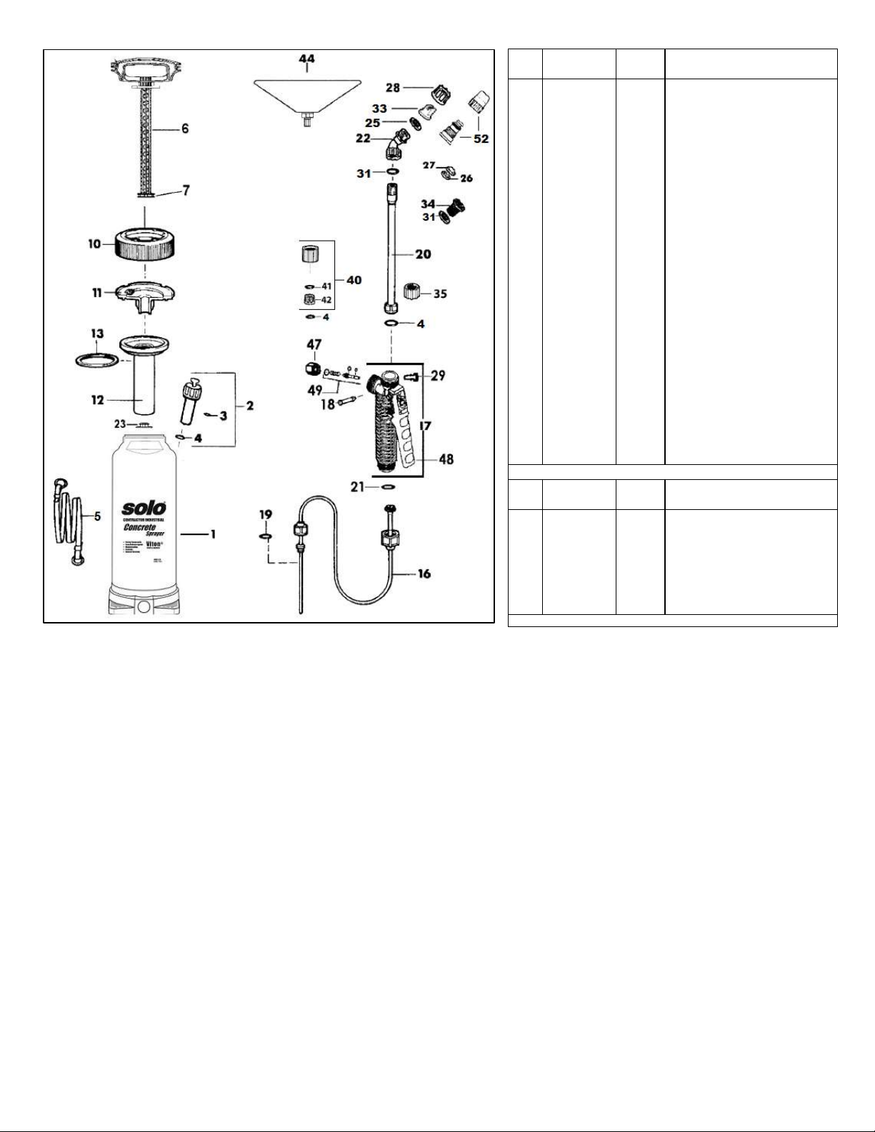
1. Nozzle cap
2. Retaining nut
3. Nozzle body
4. Filter with gasket
5. Elbow
mineral spirits for oil-based chemicals, into the tank.
•Pressurize and spray through system until all liquid is gone.
•Repeat process with warm soapy water.
•Repeat process with warm clear water.
•Use an absorbent cloth to dry all internal surfaces.
•Follow the recommendations of the chemical manufacturer for
disposing of waste water and chemicals.
•Do not use aggressive or abrasive cleaning agents.
REMOVING ADJUSTABLE NOZZLE
Unscrew the nozzle cap (1) from the nozzle body (3). This
is best accomplished while the retaining nut (2) is securely
fastened to the elbow (5). Next, unscrew the retaining nut (2).
Push the nozzle body (3) out of the retaining nut (2). Tore-
install the nozzle, reverse the above instructions.
OPERATION:
•Before using sprayer with chemicals, fill sprayer with fresh
water to assure that you have it properly assembled;
pressurize and then practice spraying. When thoroughly
familiar with sprayer operation, follow normal operating
procedures.
•Turn pump handle counter clockwise to remove pump.
•Fill tank with premixed formula up to desired level. (Do not
exceed maximum fill mark.) Observe recommendations of
chemical manufacturer.
•Tighten cap and pump assembly for a good seal.
•Pump to a maximum 45 psi or 3 bar pressure. The valve
stem on the pressure relief valve will rise up to vent excess
pressure over 45 psi.
•Start or stop spraying by squeezing or releasing the lever on
the shut-off valve. The spray pressure can be monitored with
an optional pressure gauge.
•Prior to every removal of pump, release pressure first by
pulling up on the pressure relief valve stem.
MAINTENANCE:
•Prior to storage, empty, clean and dry sprayer.
•Always store the sprayer in a dry area, protected from
freezing, heat and sunlight.
•Lubricate O-ring in pressure relief valve with non-
water-soluble grease (Silicone grease for model 388)
on a regular basis.
Disassembly: Unscrew pressure relief valve from tank
and pull the valve body out of the screw cap. Clean,
lubricate, and replace.
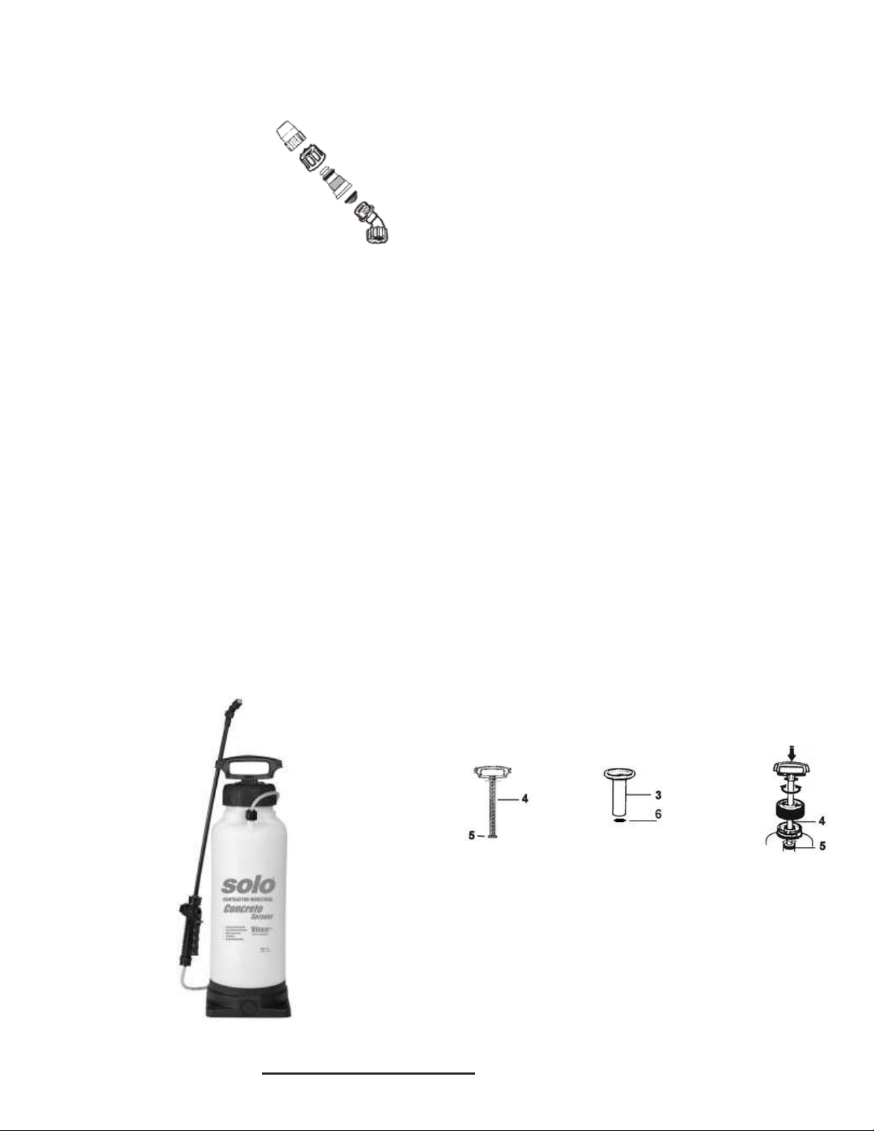
•Pump Maintenance: Pump pressure sealing is accomplished
with an O-ring (5) on the pump piston (4) which moves
within the cylinder (3). Periodically this O-ring should be
greased with a non-water-soluble grease (Silicone Grease
for model 388). If worn, it should be replaced. A small
umbrella valve (6) at the bottom of the cylinder prevents the
formula from entering the cylinder. Keep these parts clean
and replace if worn.
Disassembly: Unscrew pump assembly from tank.
Carefully remove umbrella valve (6) from the bottom of
cylinder (3). While holding cylinder firmly with one hand
and the handle of the pump piston (4) firmly in the other,
with the piston fully inserted in the cylinder, pull back on
the piston quickly and forcefully. To re-assemble, place
the piston assembly back into cylinder, place heel of
hands on opposite sides of the tank cap, while keeping
cylinder in place with fingers, tap bottom of cylinder
against a flat padded surface. Assembly will lock into
place.
•Tank Cap: A small amount of non-water-soluble grease
(Silicone Grease for model 388) on tank cap threads
and the gasket eases tightening and loosening.
•Regular Inspection: Inspect and replace worn or damaged
parts promptly. Pay particular attention to tank cap gasket,
pressure relief valve and seal, inflation valve (if fitted),
umbrella valve, O-rings and seals throughout sprayer. Regular
lubrication of O-rings and seals is recommended. (Silicone
Grease for model 388)
* Solo Model 378 –Use Solo Superior Grease or petroleum jelly.
*Solo Model 388 –Use a Silicone based lubricant.
6

3
378 PARTS BREAKDOWN * Solo Model 378 –Use Solo Superior Grease or petroleum jelly.
Prices and technical specifications are subject to change without notice.
SOLO LIMITED WARRANTY
Solo Incorporated guarantees the original purchaser of Solo equipment, that any failure of Solo manufactured parts
due to defects in material and workmanship occurring during the applicable warranty period will be repaired or
replaced without charge for parts or labor, except for those items not covered by warranty.
CONSUMER LIMITED WARRANTY: Solo equipment purchased for consumer use is covered by this Limited Warranty for a
period of ONE (1) YEAR.
COMMERCIAL LIMITED WARRANTY: Solo equipment purchased for commercial use is covered by this Limited Warranty for
a period of ONE (1) YEAR.
OPERATOR’S OBLIGATION AND RESPONSIBILITY: proof of purchase must be provided by the owner in order to obtain
warranty service. Should any failure covered by this Limited Warranty occur, deliver or ship the Solo products or parts to an
authorized Solo service center. Freight, packing and insurance costs, if any, will be borne by the owner. Follow normal
maintenance service to include applicable lubrication*, operation and storage of the product as explained in the operator's
manual.
ITEMS NOT COVERED BY WARRANTY: provisions of the Limited Warranty will not apply to the following: Any indirect or
consequential damages that may result from the failure or malfunction of the Solo product. Normal service requirements arising
during the warranty period, such as cleaning, normal wear, lubrication,filter,spray tips, etc. Normalservice work over and above
the repair or replacement of defective parts. Any failure that results from an accident, customer abuse, normal wear, neglect or
failure to operate the product in accordance with the instructions provided in the operator’s manual or provided with the product.
When an alteration or modification has been performed on a Solo product, Solo is responsible only for products as originally
furnished by Solo, provided the alterations or modifications do not adversely affect the product’s operation, performance or
durability. Parts or accessories that are incompatible with the product are not approved for use by Solo. Full disclosure of Solo’s
Limited Warranty is available from your local Solo dealer or Solo Incorporated, 5100 Chestnut Avenue, Newport News, Virginia
23605. This Limited Warranty gives you specific legal rights and you may also have other rights which vary by state.
P os. Orde r F or D e crip tio n
No. No. Model
1 14763 378 Tank with base, 3 gallon
2 4800188 Pressure relief valve assy.
30062248 ✷O-ring
40062356 ✷O-ring
54300245 Carrying strap
6407383517 Pump pistion
7 0062149 ✷O-ring
10 4073111 Tank cap, black
11 407438717 Cylinder support (requiers 2)
12 4073834 Cylinder
13 4061346 ✷Gasket, cap
16 4900515 Pressure hose assy. (incl. 19 & 21)
17 4800170 Shut-off valve assy.
18 4074295 Pin, retaining
19 0062148 ✷O-ring
20 4900230 Wand assy. (incl. 4 & 35)
21 0062358 O-ring
22 4074527 Elbow
23 0094309 ✷Umbrella valve
25 0062357 O-ring
26 4074756 Swirl plate
27 4074758 Jet cap nozzle
28 4074148 Retaining nut
29 4074329 Lock clip
31 0062359 O-ring
33 10F110 Flat fan nozzle (1gpm)
-4074263 Flat fan nozzle (.4gpm)
35 4074337 Retaining nut
47 4074336 Retaining nut
48 4074335 Lever
49 0610402-K Shut-off valve repair kit
52 4900527 Plastic adj. nozzle
- 17-559-1 Inflation valve, metal
P os. Orde r F or D e crip tio n
No. No. Model
✷4900407-K 378 Sprayer repair kit
34 2700316 No drip check valve
40 4900622 Pressure Gauge assy.
41 0062249 O-ring
42 4074338 Retaining nut
44 4900430 Drift guard
-4900207 Brass adj. nozzle
- 0065210 Brass flat fan nozzle (.2gpm)
-4400258 378 Complete pump (incl. 6,7,10-13,23)
Accessories
✷Included in Sprayer repair kit 4900407-K

4
388 PARTS BREAKDOWN *Solo Model 388 –Use a Silicone based lubricant.
Prices and technical specifications are subject to change without notice.
WARNING: Handling the brass parts of this product will expose you to lead, a chemical known by the State of
California to cause cancer and birth defects or other reproductive harm. Wash hands after handling. For more information,
go to www.P65Warnings.ca.gov.
Note: Always wear rubber gloves, safety goggles and appropriate protective clothing when repairing a sprayer.
Once a repair is completed, fill the unit with clean water, pressurize, and check for leaks. If the sprayer leaks, DO
NOT USE. Repair leaks and re-check.
P os. Orde r F o r D e crip tio n
No. No. Model
1 14763 388 Tank with base, 3 gallon
2 4800186 Pressure relief valve assy.
30062365 ✷O-ring
40062363 ✷O-ring
54300245 Carrying strap
6407383517 Pump pistion
70062369 ✷O-ring
10 4073111 Tank cap, black
11 407438717 Cylinder support (requiers 2)
12 4073834 Cylinder
13 4061347 ✷Gasket, cap
16 4900571 388 Pressure hose assy. (incl. 19 & 21)
17 4800245 Shut-off valve assy.
18 4074295 Pin, retaining
19 0062371 ✷O-ring
20 4900421 Brass wand assy. (incl. 4 &35)
21 0062364 ✷O-ring
22 4074527 Elbow
23 0094352 ✷Umbrella valve
25 CI-TP8005 Brass flat fan nozzle (.5gpm)
26 CI-TX-26 Brass hollow cone nozzle (.4gpm)
27 CI-TX-12 Brass hollow cone nozzle (.2gpm)
28 4074148 Retaining nut
29 4074329 Lock clip
31 0062368 ✷O-ring
34 2700316 No drip check valve
35 4074337 Retaining nut
47 4074336 Retaining nut
48 4074335 Lever
52 4900527 Plastic adj. nozzle
- 17-559-1 Inflation valve, metal
P os. Orde r F o r D e crip tio n
No. No. Model
✷4900406-K 388 Sprayer repair kit
40 4900622 Pressure Gauge assy.
41 0062249 O-ring
42 4074338 Retaining nut
44 4900430 Drift guard
-4900207 Brass adj. nozzle
- 0065210 Brass flat fan nozzle (.2gpm)
-4400259 388 Complete pump (incl. 6,7,10-13,23)
Accessorie s
✷Included in Sprayer repair kit 4900406-K
✷✷ Included in Shut-off valve assy. 4800245
This manual suits for next models
1
Other Solo Paint Sprayer manuals

Solo
Solo 456 User manual

Solo
Solo 425 Classic User manual

Solo
Solo 460 Li User manual

Solo
Solo 425 Comfort User manual

Solo
Solo 460 Li User manual

Solo
Solo 201 User manual

Solo
Solo 462 User manual

Solo
Solo 478-EN Installation and operation manual

Solo
Solo 201 User manual

Solo
Solo 425 Classic Installation and operation manual
Popular Paint Sprayer manuals by other brands

Black & Decker
Black & Decker BDPH200B instruction manual

Carlisle
Carlisle MS Elite 805700 Service manual

Eastwood
Eastwood Elite Concours CC500 instructions

Graco
Graco FinishPro 290 Operation

Silvan Selecta
Silvan Selecta Oktopus 500L Operator's manual

Earlex
Earlex SPRAY STATION HV3500 Operating instructions manual