manuals.online logo
Brands
  1. Home
  2. •
  3. Brands
  4. •
  5. Sony
  6. •
  7. Control Panel
  8. •
  9. Sony BKDS-7025 Instruction Manual

Sony BKDS-7025 Instruction Manual

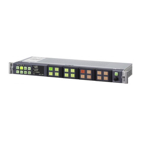
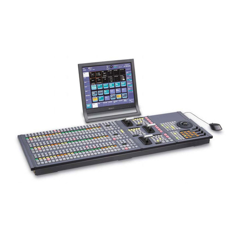
BKDS-7025
SWITCHER CONTROL PANEL
OPERATION AND MAINTENANCE GUIDE
1st Edition
Serial No. 10001 and Higher
警告
電気製品は、安全のための注意事項
を守らないと、火災や人身事故にな
ることがあります。
•ご使用にあたっては、デジタルビデオスイッチャー
DVS-7200のプロセッサー本体に付属のオペレー
ションマニュアルの「安全のために」をよくお読み
ください。
•本機は電源スイッチを備えていません。
設置の際は、本機の近くの容易に接近できる屋内配
線内に専用ブレーカーまたはスイッチを設けるか、
または本機の使用中でも容易に抜き差しできるコン
セントに電源コードを接続してください。
万一、異常が起きた場合は
専用ブレーカーまたはスイッチをOFFにするか、電
源コードを抜いてください。
WARNING
To prevent fire or shock hazard, do not expose the unit to rain
or moisture.
To avoid electrical shock, do not open the cabinet. Refer
servicing to qualified personnel only.
VORSICHT
Um Feuergefahr und die Gefahr eines elektrischen Schlages
zu vermeiden, darf das Gerät weder Regen noch
Feuchtigkeit ausgesetzt werden.
Um einen elektrischen Schlag zu vermeiden, darf das
Gehäuse nicht geöffnet werden. Überlassen Sie
Wartungsarbeiten stets nur einem Fachmann.
For the customers in the USA
This equipment has been tested and found to comply with
the limits for a Class A digital device, pursuant to Part 15 of
the FCC Rules. These limits are designed to provide
reasonable protection against harmful interference when the
equipment is operated in a commercial environment. This
equipment generates, uses, and can radiate radio frequency
energy and, if not installed and used in accordance with the
instruction manual, may cause harmful interference to radio
communications. Operation of this equipment in a
residential area is likely to cause harmful interference in
which case the user will be required to correct the
interference at his own expense.
You are cautioned that any changes or modifications not
expressly approved in this manual could void your authority
to operate this equipment.
This device requires shielded interface cables to comply with
FCC emission limits.
This symbol is intended to alert the user to the
presence of important operating and
maintenance (servicing) instructions in the
literature accompanying the appliance.
WARNING: THIS WARNING IS APPLICABLE FOR USA
ONLY.
If used in USA, use the UL LISTED power cord specified
below.
DO NOT USE ANY OTHER POWER CORD.
Plug Cap Parallel blade with ground pin
(NEMA 5-15P Configuration)
Cord Type SJT, three 16 or 18 AWG wires
Length Less than 2.5 m (8 ft 3 in)
Rating Minimum 10 A, 125 V
Using this unit at a voltage other than 120V may require the
use of a different line cord or attachment plug, or both. To
reduce the risk of fire or electric shock, refer servicing to
qualified service personnel.
Für Kunden in Deutschland
Dieses Produkt kann im kommerziellen und in begrenztem
Maße auch im industriellen Bereich eingesetzt werden. Dies
ist eine Einrichtung, welche die Funk-Entstörung nach
Klasse B besitzt.
For the customers in the United Kingdom
WARNING
THIS APPARATUS MUST BE EARTHED.
IMPORTANT
The wires in this mains lead are coloured in accordance with
the following code:
Green-and-yellow: Earth
Blue: Neutral
Brown: Live
As the colours of the wires in the mains lead of this apparatus
may not correspond with the coloured markings identifying
the terminals in your plug proceed as follows:
The wire which is coloured green-and-yellow must be
connected to the terminal in the plug which is marked by the
letter E or by the safety earth symbol Yor coloured green or
green-and-yellow.
The wire which is coloured blue must be connected to the
terminal which is marked with the letter N or coloured black.
The wire which is coloured brown must be connected to the
terminal which is marked with the letter L or coloured red.
WARNING
This unit has no power switch.
When installing the unit, incorporate a readily accessible
disconnect device in the fixed wiring, or connect the power
cord to a socket-outlet which must be provided near the unit
and easily accessible.
If a fault should occur during operation of the unit, operate
the disconnect device to switch the power supply off, or
disconnect the power cord.
WARNUNG
Dieses Gerät hat keinen Netzschalter.
Beim Einbau des Geräts ist daher im Festkabel ein leicht
zugänglicher Unterbrecher einzufügen, oder das Netzkabel
muß mit einer in der Nähe des Geräts befindlichen, leicht
zugänglichen Wandsteckdose verbunden werden.
Wenn während des Betriebs eine Funktionsstörung auftritt,
ist der Unterbrecher zu betätigen bzw. das Netzkabel
abzuziehen, damit die Stromversorgung zum Gerät
unterbrochen wird.
概要
BKDS-7025はデジタルビデオスイッチャーDVS-7200のコントロール
パネルです。別売りの以下のコントロールパネルを組み込むことがで
きます。
•キーフレームコントロールパネルユニットBKDS-7030
•DMEコントロールパネルユニットBKDS-7031
•メモリーリコールコントロールパネルユニットBKDS-7033
取り扱い操作、設置に関する情報について
本機の操作方法については、オペレーションソフトウェアBZS-7050に
付属のUser’sGuideをご覧ください。
また、本機の接続については、DVS-7200のプロセッサー本体に付属
のOperationManualをご覧ください。
なお、本機の設置については、その作業を誤ると、火災・感電やその
他の事故により、けがをしたり周辺の物品に損害を与えることがあり
ます。危険を避けるため、設置作業はサービストレーニングを受けた
技術者にご依頼ください。
本機を設置する技術者へ
設置については、DVS-7200に付属のInstallationManualをご覧く
ださい。
仕様
一般
電源 AC100〜240V±10%、50/60Hz
消費電流 最大1.0A
温度範囲 0〜40℃(動作保証)
10〜35℃(性能保証)
−20〜+60℃(保存)
外形寸法(幅/高さ/奥行き)
本体:1,290×142×532mm
(ディスプレイパネル装着時:1,290×350×
573mm)
ディスプレイパネル:499×45×197mm
質量 36kg
入/出力コネクター
SWITCHER RS-422A規格準拠、D-sub9ピン
DME RS-422A規格準拠、D-sub9ピン
REMOTE1 RS-422A規格準拠、D-sub9ピン
REMOTE2 RS-422A規格準拠、D-sub9ピン
REMOTE3 RS-422A規格準拠、D-sub9ピン
REMOTE4 RS-422A規格準拠、D-sub9ピン
REMOTE5 RS-422A規格準拠、D-sub9ピン
TERMINAL1 RS-232C規格準拠、D-sub9ピン
TERMINAL2 RS-232C規格準拠、D-sub9ピン
DISPLAYPANEL D-sub25ピン
OPTIONPANEL D-sub25ピン
GPI D-sub25ピン
•TTL入力×8
•リレー接点出力
(AC/DC、最大30V、0.1A)×4
•オープンコレクター出力×4
付属品
D-sub25ピンケーブル、5m(1)
キートップ引き抜き工具(1)
ディスプレイ取り付け台(2)
スイッチチップ(15)
ネジ+B4×6(8)
オペレーションアンドメンテナンスガイド(1)
仕様および外観は、改良のため予告なく変更することがありますが、
ご了承ください。
Printed in Japan
1997.07.13
© 1997
Image & Sound Communication Company
Published by Engineering Services Dept.
Sony Corporation
BKDS-7025 (SY,和,英)
3-860-691-01(1)
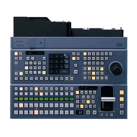
Overview
The BKDS-7025 is a control panel for the DVS-7200
Digital Video Switcher. The following optional
control panels may be installed in this control panel:
•BKDS-7030 Key Frame Control Panel Unit
•BKDS-7031 DME Control Panel Unit
•BKDS-7033 Memory Recall Control Panel Unit
Instructions about Operation and
Installation
For operating instructions, refer to the User’s Guide
supplied with the BZS-7060 Operation Software, and
for instructions about connections, the Operation
Manual supplied with the DVS-7200 Digital Video
Switcher.
Note that if this unit is installed incorrectly, personal
injury or damage to peripheral items may occur due to
fire, shock, or other accidental circumstances. To
avoid such risks, installation should be performed by
trained service technicians.
To technicians installing the unit
Please refer to the Installation Manual supplied with
the DVS-7200 for installation instructions.
Specifications
General
Power requirements
100 to 240 V AC ±10%, 50/60 Hz
Current consumption
1.0 A maximum
Temperature range
Operation guaranteed
0 to 40˚C (32 to 104˚F)
Performance guaranteed
10 to 35˚C (50 to 95˚F)
Storage –20 to +60˚C
(–4 to +140˚F)
Dimensions (w/h/d, excluding projections)
Mainframe: 1,290 ×142 ×532mm (507/8×55/8
×21 inches)
(when assembled with display panel)
1,290 ×350 ×573mm (507/8×
137/8×225/8 inches)
Display panel: 499 ×45 ×197mm
(193/4×113/16 ×77/8 inches)
Mass 36 kg (79 lb 5 oz)
Input/output connectors
SWITCHER Complies with RS-422A standard,
D-sub 9-pin
DME Complies with RS-422A standard,
D-sub 9-pin
REMOTE 1, REMOTE 2, REMOTE 3, REMOTE 4,
REMOTE 5 Comply with RS-422A standard,
D-sub 9-pin
TERMINAL 1, TERMINAL 2
Comply with RS-232C standard,
D-sub 9-pin
DISPLAY PANELD-sub 25-pin
OPTION PANEL D-sub 25-pin
GPI D-sub 25-pin
•8 inputs, TTL
•4 inputs, relay contact
(AC/DC, 30 V max., 0.1 A)
•4 outputs, open collector
Accessories supplied
D-sub 25-pin cable, 5m (16 ft) (1)
Key top removing tool (1)
Display panel attachments (2)
Switch chips (15)
Screws, +B4 ×6 (8)
Operation and Maintenance Guide (1)
Design and specifications are subject to change
without notice.

Other Sony Control Panel manuals

Sony CCP-9000-C User manual

Sony

Sony CCP-9000-C User manual

Sony ICP-X7000 User manual

Sony

Sony ICP-X7000 User manual

Sony ICP-X7000 User manual

Sony

Sony ICP-X7000 User manual

Sony RCP-TX7 User manual

Sony

Sony RCP-TX7 User manual

Sony CCP-8000 Series User manual

Sony

Sony CCP-8000 Series User manual

Sony MVS-8000 User manual

Sony

Sony MVS-8000 User manual

Sony RCP-1500 User manual

Sony

Sony RCP-1500 User manual

Sony ICP-X1116 User manual

Sony

Sony ICP-X1116 User manual

Sony SRP-X700P User manual

Sony

Sony SRP-X700P User manual

Sony RCP-730 User manual

Sony

Sony RCP-730 User manual

Sony RCP-TX7 User manual

Sony

Sony RCP-TX7 User manual

Sony RCP-750 User manual

Sony

Sony RCP-750 User manual

Sony MSU-1000 User manual

Sony

Sony MSU-1000 User manual

Sony ICP-6520 User manual

Sony

Sony ICP-6520 User manual

Sony BKDM-3020 User manual

Sony

Sony BKDM-3020 User manual

Sony DMW-C1 User manual

Sony

Sony DMW-C1 User manual

Sony RM-X7BT User manual

Sony

Sony RM-X7BT User manual

Sony RCP-TX7 User manual

Sony

Sony RCP-TX7 User manual

Sony UCP-8060E User manual

Sony

Sony UCP-8060E User manual

Sony BKP-5973 User manual

Sony

Sony BKP-5973 User manual

Sony RCP-3100 User manual

Sony

Sony RCP-3100 User manual

Sony BKMA-506 User manual

Sony

Sony BKMA-506 User manual

Sony DME-3000 User manual

Sony

Sony DME-3000 User manual

Sony BKS-R6010 User manual

Sony

Sony BKS-R6010 User manual

Popular Control Panel manuals by other brands

MORLEY-IAS ZXa Commissioning manual

MORLEY-IAS

MORLEY-IAS ZXa Commissioning manual

Soundoff Signal ENGSCP7141 quick start guide

Soundoff Signal

Soundoff Signal ENGSCP7141 quick start guide

Fracarro DEFENDER64 quick guide

Fracarro

Fracarro DEFENDER64 quick guide

GST GST-FT40N Installation and operation manual

GST

GST GST-FT40N Installation and operation manual

Eclipse ACC970 instruction manual

Eclipse

Eclipse ACC970 instruction manual

Satel VERSA IP Installer manual

Satel

Satel VERSA IP Installer manual

NAPCO Gemini GEM-P3200 Programming instructions

NAPCO

NAPCO Gemini GEM-P3200 Programming instructions

Kramer RC-5B2 installation instructions

Kramer

Kramer RC-5B2 installation instructions

Coloronix SCC3 Manual guide

Coloronix

Coloronix SCC3 Manual guide

VDH LNG EXT RS_OS Vimar Eikon 3M Z installation manual

VDH

VDH LNG EXT RS_OS Vimar Eikon 3M Z installation manual

Riello 20081467 manual

Riello

Riello 20081467 manual

RHINO SMS8 instructions

RHINO

RHINO SMS8 instructions

Fenwal EX 200 Installation, operation and maintenance manual

Fenwal

Fenwal EX 200 Installation, operation and maintenance manual

Braeburn Economy Series Installer's guide

Braeburn

Braeburn Economy Series Installer's guide

C & K Systems Securit 802 Features

C & K Systems

C & K Systems Securit 802 Features

Green Brook 12VFC Installation & operating instructions

Green Brook

Green Brook 12VFC Installation & operating instructions

ALL-FILL B-SV-600 user manual

ALL-FILL

ALL-FILL B-SV-600 user manual

SIGMA TEK ETV 0833-3 operating manual

SIGMA TEK

SIGMA TEK ETV 0833-3 operating manual

manuals.online logo
manuals.online logoBrands
  • About & Mission
  • Contact us
  • Privacy Policy
  • Terms and Conditions

Copyright 2025 Manuals.Online. All Rights Reserved.