SORG Loop Service manual

Service Record LoopSORG 1 of 44
2019-08-15 Besondere Menschen, besondere Lösungen.
ENG
Unique people, unique solutions.
LoopSORG
Service Record LoopSORG
Service Record
In the following all individual adjustments of the wheelchair are
described. These adjustments require tools and specialised
knowledge. Please leave the adjustments to a qualied rehab
consultant.

2 of 44 Service Record LoopSORG 2019-08-15
Imprint
SORG Rollstuhltechnik GmbH+Co.KG
Benzstraße 3-5
68794 Oberhausen-Rheinhausen / Germany
Tel. +49 7254-9279-0
Fax +49 7254-9279-10
E-Mail [email protected]
Web www.sorgrollstuhltechnik.de
Revision status
2019-08-15
Technical status
Technical changes and misprints reserved. The
pictures in this Instructions for use can dier
from the actual equipment components. How-
ever, a corresponding conduction is possible.
Copyright
All texts, pictures and graphics underlie co-
pyright protection. All rights, including co-
pying, publishing, editing and translating,
remain reserved. © by SORG Rollstuhltech-
nik GmbH+Co. KG Benzstraße 3-5, 68794
Oberhausen-Rheinhausen / Germany.
Our terms and conditions can be found
on our order forms and at www.sorgrollstuhl-
technik.de/impressum.

Service Record LoopSORG 3 of 44
2019-08-15
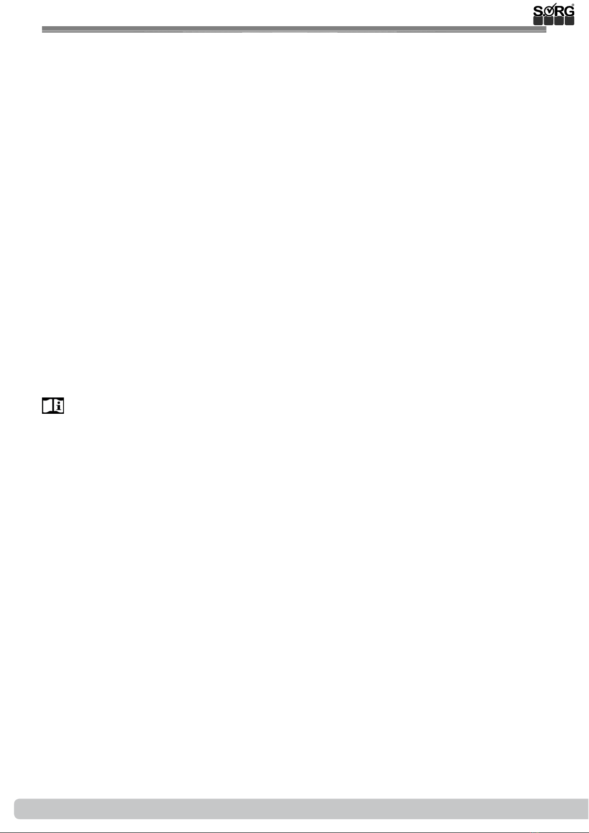
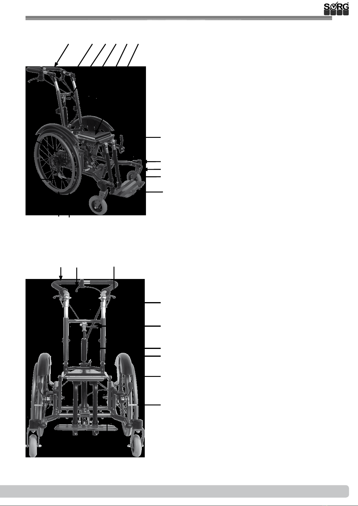
1 Seat shell base frame overview 5
2 General information 6
2.1 General indications 6
2.2 Documentation indications 6
2.3 Required torques and tools 6
2.4 Explanation of symbols 7
2.5 General safety instructions 8
3 Assembly Group 9
3.1 Assembly Group Wheels 9
3.1.1 Position rear wheel 9
3.1.2 Displacing the wheels without a
camber adapter (20",22",24") 9
3.1.3 Displacing the wheels with a
camber adapter (20",22",24") 10
3.1.4 12"/16" wheels 10
3.1.5 Camber 11
3.1.6 Wheel base extension for 20" + 22"12
3.1.7 Casters 13
3.2 Assembly Group Frame 14
3.2.1 Frame arch for closed frames 14
3.2.2 Widening the frame 15
3.2.3 Additional crossbar 16
3.3 Assembly Group Seat 17
3.3.1 Adjusting the tilting direction 17
3.3.2
Displacing the seat plate horizontally
18
3.3.3 Displacing the seat plate vertically 19
3.3.4 Position wedge adapter 19
3.3.5 Release lever-seat wedge 20
3.3.6 Position push bar 20
3.3.7 Double gas spring 21
3.4 Assembly Group Back 25
3.4.1 Setting back depth 25
3.4.2 Setting height of the push bar 25
3.4.3 Setting back angle 25
3.4.4 Adjustment of back guide 26
3.4.5 Conversion from back angle
setting to back angle adjustment 27
3.4.6 Changing the basic setting of the
push height 27
3.5 Assembly Group Leg Supports 28
3.5.1 Positioning the leg supports 28
3.5.2 Leg supports: standard or angle
adjustable 29
3.5.3
Leg supports which swing to the side
30
3.5.4 Leg support can be elevated with
a physiological turning point 31
3.5.5 Multidirectional leg support 33
3.6 Assembly Group Brakes 34
3.6.1 Trum brake 34
3.6.2 Knee lever brake 36
3.7 Assembly Group Frame 37
3.7.1 Anti-tipper 37
3.7.2 Tipping lever 37
3.7.3 Outdoor Front End 38
4 Repairs and maintenance 39
4.1 Repairs 39
4.2 Spare parts 39
4.3 Maintenance 39
4.4 Disinfection 39
4.5 Storage 39
4.6 Reinstatement 40
4.7 Disposal 40
4.8 Maintenance/ Inspection 40
5 Technical specications 42
5.1 Data and measurements 42
5.2 Meaning of labels 43
5.3 Declaration of conformity 43
Table of content

4 of 44 Service Record LoopSORG 2019-08-15

Service Record LoopSORG 5 of 44
2019-08-15
1 Seat shell base frame overview
1push handle
2eccentric tensioner for angle adjustment of
the push handle
3gas pressure spring
4handle for height adjustment of the
push handle
5wheel cover
6wedge and wedge adapter
7brake lever
8caster housing
9caster fork
10 caster
11 Foot plate
12 rear wheel
13 handrim
14 anti-tipper
15 axle plate
16 push handle
17 release lever for seat tilt
18 control lever for drum brake
19 rccentric tensioner for angle adjustment of
the push handle
20 control lever for angle adjustment of the
back
21 gas pressure spring to adjust the back angle
22 wheel cover
23 handrim
24 brake pressure pin of the cable brake
25 bar to widen the frame
26 foot plate
12356
7
8
9
10
11
1213
4
16 17 18
19
21
22
23
24
2526
14
15
20

6 of 44 Service Record LoopSORG 2019-08-15
2 General information
2.1 General indications
In the following all individual settings, adjustments and repairs as well as the yearly inspection of
the wheelchair are described. These adjustments require tools and specialised knowledge. Ple-
ase leave the adjustments to a qualied rehab consultant.
Should questions or suggestions come up then please contact your medical supply store or our
team (+49 7254 9279-0).
2.2 Documentation indications
Please note:
• Information about before sale can be found in the instructions for use
• Infomation for the user can be found in the instructions for use
• For maintenance instructions see: Chapter 4 (Repair & Maintenance)
2.3 Required torques and tools
For the following screws needed torque:
• M5: 5 Nm;
• M6: 7 Nm;
• M6 (axle plate) 10 Nm
• M8: 20 Nm;
• M10 (nut): 25 Nm; (caster)
• quick release axle tting 40 Nm
Needed tools:
• torque wrench (5-50 Nm)
• open end wrench
• ex ratchet handle with socket wrench inserts
• hexagon screw driver
• Phillips screw driver
• at head screw driver
• plastic mallet
• side cutter
• threadlocker (uid)
• bicycle inner tube repair kit
• work bench/jaw vise with rubber pads

Service Record LoopSORG 7 of 44
2019-08-15
2 General information
2.4 Explanation of symbols
ATTENTION! Warnings for perso-
nal Safety aspects that are of the
utmost importance.
CORRECT safety adjustment/ use
WRONG adjustment/ use
NOT ALLOWED
References to additional/conti-
nuing reading.
Setting or adjusting the angle
open/ close
Turn clockwise
Turn counter-clockwise
steps to be done at the same
time
steps to be done after each other
steps to be done on both sides
Use
(A); (B)
1. 1.
1. 2.
;
2x
push/ pull/ insert / move/
Push in specic direction
important detail
correct or proper use/setting
incorrect or improper use/setting
reference from text to detail
point of view
view from top
view from the side
view from the bottom
view from the front
view from the back
fasten parts
remove parts

8 of 44 Service Record LoopSORG 2019-08-15
2 General information
2.5 General safety instructions
Before each use be sure to check:
• frame, back tubes, attachments and accessories for visible damage, bends, cracks or mis-
sing/loose scews,
• wheels/quick release axles for rm t,
• sucient tire pressure, tire tread,
• functionality of the brakes,
• rm t of the angle adjustment elements/ eccentric clamps,
• rm t of the seat plate/ the back/ the foot plate,
• functionality of the anti-tipper/ seat and back straps,
• if all previously disassembled parts are re-inserted or rmly locked.
There is a risk of injuries (e. g. such as bruising) on all rotating or folding parts, including
adjustments, repairs and transport.
All wheelchair parts are to be handled with care. Do not throw or drop removable parts.
Before repairs or adjustments are made, clean/didinfect the wheelchair and secure it from
tipping over and/or falling down.
Only use original spare parts.
Safety nuts may only be used once. Lossened safety nuts must be replaced by new ones.
Only the regular maintenance of all safety-relevant parts on the wheelchair by a qualied
rehab workshop protects against damage and maintains our manufacturer's warranty.
Combination with products from other manufacturers
The wheelchair may only be combined with the electrical auxiliary drives apporved by the
manufacturer. Restrictions or adaptations as well as the attachment itself must be done by the
supplier of the additional system or the authorized specialist dealer.
Please check the conditions with the manufacturerer of the audiliary drives.
In combination of wheelchair and electric auxiliary drive, certain strains can occur which
can lead to damage to the wheelchair. Slowly approach obstacles and carefully overcome
them so that little force is applied to the caster, driving wheel and wheelchair as a whole.

Service Record LoopSORG 9 of 44
2019-08-15
3.1.1 Position rear wheel
3.1 Assembly Group Wheels
Check the tilt stability of Loop while fully tilted and with the patient, after alle positioning
adjustments of the rear wheels have been made and, if necessary, modify the position.
(1)We mount:
• 24” wheels in row (A),
• 22” wheels in row (B),
• 20” wheels in row (C),
• the adapters for 12”/16” wheels are
mounted in row (D).
Position 1 is the most passive (most stable), po-
sition 5 is the most active (most wobbly). The
wheels are factory-set in position 2. In this po-
sition, you receive a horizontal frame position
with corresponding caster. Other constellations
are possible. The horizontal frame position can
be reached through the adjustment of the cast-
ers.
(A)
(B)
(C)
(D)
1
2
3
4
5
(1)
3.1.2 Displacing the wheels without a camber adapter (20",22",24")
(A)
(B)
(2)
• (2) Remove the wheels,
• remove the hexagon nut (A) of the
quick-release axle tting (B),
• place the tting (B) in the new hole,
• put the hexagon nut (A) back on, tighten
it and
• place the wheels back on.
Correct the position of the knee lever
brake and be sure that it functions properly.

10 of 44 Service Record LoopSORG 2019-08-15
(1)
(A)
(C)
(D)
(E)
(B)
3.1.3 Displacing the wheels with a camber adapter (20",22",24")
• (1) Remove the wheels,
• remove the hexagon nut (A) of the
quick-release axle tting (B),
• remove the nut (C) from the brake arm
(D) including the inner shell,
• remove both camber adapters (E) and
place them in front of the new position.
• Fixate both camber adapters (E) with the
tting (B) and the shell in the new posi-
tion,
• replace the hexagon nut (A) and tighten
it,
• replace and tighten the nut (C) from the
spacer.
The Camber adapters must always be
mounted opposite. At 0°: inner surface=
thick end facing up.
Correct the position of the knee lever
and be sure that it functions properly.
3.1 Assembly Group Wheels
3.1.4 12"/16" wheels
Changing to 12”/16” wheels subsequently:
• (2) Remove the big wheels including the
brake pad, tting and drum brake arm,
• mount the adapter (A) for the 12”/16”
wheels with the screws (B) in the bottom
hole row (C)
• mount the screw (D) with the delivered
discs in the proper hole.
• Mount the quick-release axle tting (E)
with the brake pad and the drum brake
arm (F) analogously as described above
and
• put the 12”/16” wheels on.
Be sure that the drum brake functions
properly and if necessary establish its func-
tionality (see drum brake).
Whe using a knee lever brake, this must be displaced (see knee lever brake). Correct the
position and be sure that if functions properly.
To change the camber to 0°, please proceed as described.
(B)
(C)
(D)
(E)
(F)
(A)
(2)

Service Record LoopSORG 11 of 44
2019-08-15
3.1.5 Camber
3.1 Assembly Group Wheels
To change the camber with a wheel base extension, please proceed as described here.
(2)
(A)(C)
(D)
(E)
(B)
Changing the camber subsequently:
• (2) remove the rear wheels,
• remove the hexagon nut (A) of the
quick-release axle tting (B),
• remove the nut (C) from the drum brake
arm including the inner surface shell.
• Place both camber adaptors (D+E) in
front of the position wanted: (D) thick
end down; (E) thick end up-
• Fixate both with the tting (B) and the
shell from the drum brake spacer in the
new position,
• replace the hexagon nut (A) and tighten
it,
• replace the nut (C) of the drum brake
arm and tighten it.
Be sure that the drum brake functions
properly and if necessary, establish its func-
tionality (see drum brake).
Correct the position of the knee lever
brake an be sure that it functions properly
(see knee lever brake).

12 of 44 Service Record LoopSORG 2019-08-15
3.1.6 Wheel base extension for 20" + 22"
To prepare the extension of the wheelbase:
remove the wheels completely on both sides
incl. brake body, tting etc.
remove the wheel guard completely,
if necessary remove the anti-tipper completely.
To extend the wheelbase
• (1) mount the wheelbase extension (A)
and the connecting plate (B) with the
screws (C),
• Mount the quick-release axle tting (D)
in the corresponding hole and
• Adjust the drum brake counterholder
(E) in the corresponding hole.
To move the clothes guard:
• (1) Move the clothes guard (F) back
and secure it with the corresponding
screws (G).
To adjust the clothing protection:
• (2) Replace the wheels and adjust the
clothes guard on the existing holes (A)
and slots (B).
To move the knee lever brake:
• (3) Replace the standard brake adapter
with the brake adapter for wheelbase
extensions (A).
• Adjust the knee lever brakes (B)
Check the functionality of the drum bra-
ke and restore it if necessary.
Correct the position of the knee lever
brake and then check its functionality.
To change the camber to 0 ° please proceed as
described there.
3.1 Assembly Group Wheels
(1)
(E)
(B)
(G)
(A)
(F)
(D)
(C)
(A)
(B)
(2)
(A)
(B)
(3)

Service Record LoopSORG 13 of 44
2019-08-15
3.1.7 Casters
3.1 Assembly Group Wheels
If you would like to add a frame arch so that the
frame is closed in the front and more resilient:
• (2) Remove the caster adapters from
both sides (A) including the half shells
(B),
• put the frame arch (C) on and attach it
from the top with the screws (D),
• move the caster adapters (A) out of
the old holes (E+F) into the new holes
(F+G),
• mount the adapters (A) including half
shells (B) with the screws (H) in the new
position and adjust as described above
the casters in an absolute vertical posi-
tion.
Correct the position of the knee lever
brake and be sure that if functions properly
(see knee lever brake)
After every change made on the casters
the steering head tendency must be newly
adjusted.
(1)
(B)
(C)
(A)

14 of 44 Service Record LoopSORG 2019-08-15
3.2.1 Frame arch for closed frames
3.2 Assembly Group Frame
For retrotting the frame bow for a frame
closed at the front, proceed as follows on both
sides of the frame:
• (1) Remove on both sides the steering
wheel adapter (3A) incl. Half-shells
(3B),
• if necessary, remove the knee lever
brakes
• and remove the caps at the end of the
frame tubes (A) and (B).
• (2) Secure the supplied sleeve (C) with
the screw (D) in the hole (E) provided.
• Insert the frame into the bottom frame
tube (C) with the bottom frame tube
(F).
• Screw the frame bow at the top with the
(G) screw to the sleeve (C).
• Check the tightness of the ttings
(D+G).
• (3) Move the steering wheel adapters
(A) and half shells (B) from the old
holes (E+F) into the new holes (F+G),
• Mount the adapters (A) of the half-
shells (B) with the screws (H) in the new
position (F+G)
• and adjust as described
• Possibly. you must re-assemble and
adjust the toggle brakes
Every change made on the seat and/ or
the tilting, the tilt behavior of the Loop must
be newly tested and practiced with a pas-
senger and the help of an experienced and
strong person.
(A) (B)
(C)(D)(E) (F)
(G)
(A)
(E) (F) (G)
(H)
(B)
(1)
(2)
(3)

Service Record LoopSORG 15 of 44
2019-08-15
3.2.2 Widening the frame
3.2 Assembly Group Frame
To widen the frame:
• (1+2) remove both wheels,
• remove the screwing (A) from the cross-
bars (B) completely on one side,
• (2) remove the screwing (C) from the
seat board including the shell (D) com-
pletely.
• Displace both crossbars (1B) in the nec-
essary size along the prepared holes on
the crossbar adapters 1 or 2 cm by put-
ting the screws (1A) loosely back in.
• Place one or two shells (2E) on the outer
side (1 shell=1 cm, 2 shells=2 cm),
• place the screwing (2C) back through
the shell.
• Tighten all screw connections (1A and
2C).
• Precede the same with the screw con-
nections (1A and 2C) on the other side.
Please regard the next chapter if your LoopSORG
has an additional crossbar.
Both crossbars must be displaced in the
same distance on both sides. An asymmetri-
cal assembly is dangerous and not allowed.
(1)
(2)
(A)
(C)
(C) (B)
(D)
(E)

16 of 44 Service Record LoopSORG 2019-08-15
3.2.3 Additional crossbar
To xate the additional crossbar under the seat:
• (1) remove both wheels,
• then remove the screw connections,
completely on one side, of the bottom
crossbar as described above,
• on the same side, remove the screw con-
nections (A) for the seat board,
• place the crossbar adapter (B) for the
top crossbar (C) in and screw it onto the
frame pipe with the screw (D).
• Place the top crossbar (C) in the wanted
hole of the crossbar adapter (B),
• with the screws (E), screw them together
in the same hole as the bottom crossbar,
• place or displace the shells from the seat
screwing (A) as described above,
• put the screws (A) back into the seat
board and tighten them rmly.
• Precede the same way on the opposite
side.
The crossbars must be displaced in the
same distance on both sides. An asymmetri-
cal assembly is dangerous and not allowed.
3.2 Assembly Group Frame
(1)
(B)
(D)
(C)
(E)
(A)

Service Record LoopSORG 17 of 44
2019-08-15
3.3.1 Adjusting the tilting direction
3.3 Assembly Group Seat
(1) The tilting direction is determined by the
position of the gas spring at the bottom of the
carrier (A) and on top on the holders under
the seat board (B) as well as by the horizontal
(C) and vertical (D) position of the seat.
We mount standardly as follows:
For tilting from -5° to +35°:
• (2) with frame size 1 and 2,
• (3) with frame size 3.
For tilting from +2,5° to +40°:
• (4) with frame size 1 and 2,
• (5) with frame size 3.
After every change made on the seat
and/ or the tilting, the tilt behaviour of the
Loop must be newly tested and practised
with a passenger and the help of an experi-
enced and strong person.
(1)
(A)
(B)
(C)
(D)
(2) (3)
(4) (5)

18 of 44 Service Record LoopSORG 2019-08-15
3.3.2 Displacing the seat plate horizontally
3.3 Assembly Group Seat
In order to displace the seat plate by 2 cm with
the same tilting direction (only possible with
frame sizes 2 and 3):
• (1) remove the screws (A) from the seat
plate (B) on both sides including the in-
ner shells completely.
• (2) Remove the screws (F and D) from
the gas spring (E) completely,
• move the seat plate (1B) to the alterna-
tive position,
• replace the shells,
• replace the screws (1A) through the shell
• and retighten the screw connections
(1A).
• Place the gas spring (2E) in the alterna-
tive position (2F and 2D),
• replace the screw
• and tighten it.
After every change made on the seat
and/ or the tilting, the tilt behaviour of the
loop must be newly tested and practised
with a passenger and the help of an experi-
enced and strong person.
If the LoopSORG equipped with two gas springs
then please precede the same.
(1)
(2)
(A)
(D)(F)
(E)
(B)
(C)

Service Record LoopSORG 19 of 44
2019-08-15
In order to displace the seat plate by 2 cm with
the same tilting direction:
• (3) loosen both screws (C) from the
guide clip on both sides and
• remove both screws from the screw con-
nection (A) of the seat unit including the
half shells (B) on both sides completely.
• (4) Remove the screw connections of the
gas spring (F) including the shells com-
pletely.
• (3) Move the seat unit with the carriers
(D) to the desired measurements in the
holes (E) (each hole is ± 2 cm),
• (4) Displace the gas spring in the holes
(G) (each hole is ± 2 cm) in the same
measurement.
• Place the screws (3A) with the half shells
(3B) in the new position and tighten
them rmly.
• Place the screws (4F) with the shells in
the connection of the gas spring and
tighten them rmly.
After every change made on the seat
and/or the tilting, the tilt behaviour of the
loop must be newly tested and practised
with a passanger and the help of an experi-
enced and strong person.
If you do not displace the seat unit and
the gas spring parallel, a dierent tilting
direction and a dierent seat adjustment will
result.
3.3.3 Displacing the seat plate vertically
3.3 Assembly Group Seat
(1)
(2)
(A)
(C)
(D)
(E)
(B)
(G)
(F)
3.3.4 Position wedge adapter
You can adjust the seat position as described
in the chapter before, horizontally and vertical-
ly through the seat plate. In addition, you can
change the position of the wedge adapter.
In order to change the position of the wedge
adapter:
• (3) loosen all four screws (A),
• push the wedge in the wanted position
• and retighten all four screws (A).
After every change made on the seat
and/ or the tilting, the tilt behaviour of the
loop must be newly tested and practised
with a passanger and the help of an experi-
enced and strong person.
(3)
(A)

20 of 44 Service Record LoopSORG 2019-08-15
3.3.5 Release lever-seat wedge
3.3 Assembly Group Seat
(1) The red release lever (A) of the wedge
adapter should stick out of the seat plate
about 1 cm.
To change the position:
• (2) loosen both screws (B),
• guide the release lever in the wanted po-
sition and
• retighten the screws (B).
With certain tilt adjustments “collisions” be-
tween gas spring and release lever can occur.
In this case, be sure that the gas spring has
enough room when the max. tilt angle is in use;
see chapter tilting
(2) (A)
(B)
3.3.6 Position push bar
(A)
(C)
(B)
(2)
~ 1 cm
If, for example, you have a great structure depth
of the seat shell on the back, the structure depth
can be compensated through the position of
the push handles.
For this:
• (2) loosen the four screws (A) of the
push bar adapter (B),
• push the ends of the pipes from the
push bar in the wanted position, forward
or backward
• and retighten all four screws (A).
After, it is important that you check the
tilt behaviour of the loop with full strain
(with a passanger) and the help of an experi-
enced and strong person.
If necessary, the centre of gravity must be
changed (wheelbase extension) and the po-
siton of the anti-tipper must be renewed.
Table of contents
Other SORG Wheelchair manuals

SORG
SORG Dynamis MV 793 User manual

SORG
SORG Siro II User manual

SORG
SORG Loop 802 Service manual

SORG
SORG Loop 802 User manual

SORG
SORG Dynamis TSD User manual

SORG
SORG Vector User manual

SORG
SORG Tilty vario Service manual

SORG
SORG Jump beta User manual

SORG
SORG kika User manual

SORG
SORG Airon 792 User manual

SORG
SORG Vector Service manual

SORG
SORG Airon Service manual

SORG
SORG MIO MOVE User manual

SORG
SORG Mio Move 604 User manual

SORG
SORG Mio Carbon Service manual

SORG
SORG Tilty vario Service manual

SORG
SORG Vector Service manual

SORG
SORG LoopSORG 802 User manual

SORG
SORG Loop RS User manual

SORG
SORG Jump alpha User manual