service record Airon 9 von 36
2021-06-10
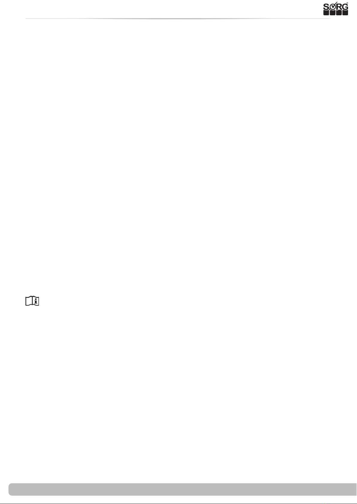
3.1 Wheels assembly
3.1.3 Rear seat height, seat inclination
(A)
(1)
(2)
(B)
(A)
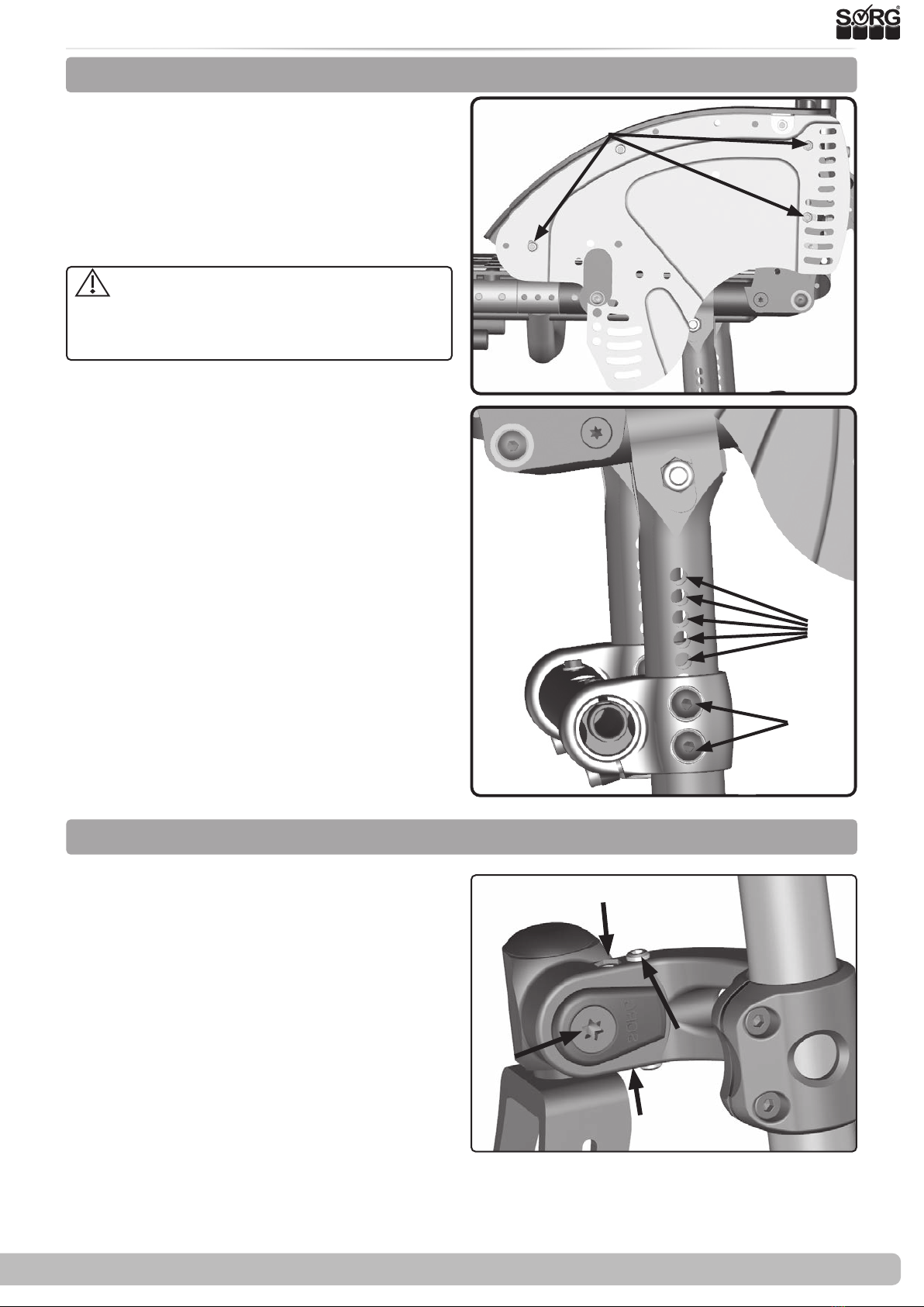
3.1.4 Positioning the steering angle
(3)
(B)
(C)
After every change to the drive wheel,
the functionality of the parking brakes must
be checked and the caster wheels and the
wheel track must be readjusted.
As a rule, the seat height at the back is selec-
ted approx. 2-3 cm lower than the seat height
in front in order to achieve a safe and comfor-
table sitting position with good distribution
of the seat pressure and to avoid "slipping
forward". However, other settings can also be
useful in individual cases.
• (1) Remove the drive wheels,
• remove the side panels / clothes guards
with the screws (1A) (simply remove the
plug-in side panels),
• (2) Remove the screw connection and
the threaded sleeves on the clamping
ange (2A),
• move the clamping ange to the desi-
red holes (2B)
• attach the screws and threaded sleeves
and tighten all screws again.
• Mount the side parts and put the drive
wheels back into the quick-release axle.
The clamping anges must be attached at the
same height on both sides. The lateral dis-
tance between the top tires and the side panel
should be as small as possible, but at least 10
mm.
An incorrectly set steering axis angle can lead to caster wheel utter and when cornering (due to
the wheel caster) to obstructive "uphill and downhill driving".
The steering axis angle must be readjusted after
each change to the rear and front seat height.
For adjusting the steering angle:
(A)
(A)
• Loosen the screws (3A) + (3C)
• Unscrew the threaded pins (3B) suci-
ently to be able to readjust the steering
head angle.
• Tighten the screws (3A) and (3C) so
that the steering head can just be mo-
ved and set the steering head angle to
90 °.
• Carefully screw in one of the threa-
ded pins (3B) until the rst resistance.
Then tighten the second set screw (3B)
against it.