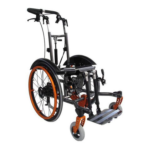
SORG Loop 802 User manual

User Manual
1
User Manual
Loop
Type 802
SORG

LoopSORG
2
IMPRINT
SORG Rollstuhltechnik GmbH+Co.KG
Benzstraße 3-5
D-68794 Oberhausen-Rheinhausen
Germany
Tel. +49 7254-9279-0
Fax +49 7254-9279-10
E-mail info@sorgrollstuhltechnik.de
Web www.sorgrollstuhltechnik.de
REVISION STATUS
Revision from September 15, 2015
TECHNICAL STATUS
Technical changes and misprints reserved. The pictures in
this user manual can – depending on the individual equip-
ment – differ from the actual equipment components. How-
ever, a corresponding conduction is possible.
rehaKIND
We are a member of rehaKIND e.V.
International association
child and adolescent rehabilitation
COPYRIGHT
© by SORG Rollstuhltechnik GmbH + Co. KG Benzstraße
3-5, 68794 Oberhausen-Rheinhausen.
All texts and pictures in this user manual underlie the
international copyright protection and are not allowed to be
published without our consent – not even in excerpts!
CERTIFICATION
We are certied according to the Quality Management
System ISO 90001:2008 under the certicate no. 12 100
20070 at TÜV SÜD.

User Manual
3
REVISION STATUS 2
TECHNICAL STATUS 2
rehaKIND 2
COPYRIGHT 2
CERTIFICATION 2
Wheelchair Overview 4
1 Preamble 5
1.1 General Information 5
1.2 Signs and Symbols 5
1.3 Indication 5
1.4 Counter Indications 5
1.5 Specification Loop 5
1.6 Application 6
1.7 Reception 6
1.8 Documentation 6
1.9 Service and Maintenance 6
1.10 Accessory and attachment drives 7
2 Safety Instructions 7
2.1 General Indications 7
2.2 Handling 8
2.2.1 Getting in and out 8
2.2.2 Starting and slowing down 8
2.2.3 Risk of tipping and flipping over 8
2.2.4 Up and downhill 8
2.3 Grabbing objects 9
2.4 Overcoming obstacles 10
2.5 Wheel lock 10
2.6 Anti-tipper 11
2.7 Casters 11
2.8 Loading and transporting 11
2.8.1 Transport in public transportation 12
2.8.2 Transport in other vehicles 12
2.9 Other Risks 12
3. Handling 13
3.1 Wheels 13
3.1.1 Quick-Release Axle Wheels 13
3.1.2 Drum brake wheels 14
3.2 casters 14
3.3 Special hand rims 15
3.3.1 Knob hand rims 15
3.3.2 Hand rim covers /
Maxgrepp hand rims 15
3.4 Back 16
3.4.1 Tilting 16
3.4.2 Positioning the back angle 16
3.4.3 Adjusting the back angle 16
3.4.4 Push handle height adjustment 17
3.4.5 Adjusting the push height 17
3.4.6 Push handle angle adjustment 17
3.4.7 Folding the back part down 18
3.4.8 Back guide for the seat shell 18
3.5 Leg Support 19
3.5.1 Standard leg support
with a continuous or divided footrest 19
3.5.2 Leg support can be elevated
with a continuous or divided footrest 19
3.5.3 Multidirectional leg support
with a divided footrest 19
3.5.4 Leg support: detachable and
swings to the side, continuous or
divided footrest 20
3.5.5 Leg support: detachable, can be
elevated and folded to the side 20
3.5.6 Locking 20
3.6 Brakes 21
3.6.1 Drum brake as driving brake 21
3.6.2 Drum brake as wheel lock 21
3.6.3 Knee lever brake (wheel lock) 21
3.6.4 Locking the wheel lock 22
3.6.5 Reverse gear stop 22
3.6.6 Anti-tipper 22
3.7 Seat Shell 23
3.7.1 Putting on/Securing 23
3.7.2 Removing/Unlocking 23
3.7.3 shortening/extending the
release lever 23
3.8 Outdoor Front End
(push aid for outside) 24
3.9 Baggage Holder 24
4. Repairs and Maintenance 25
4.1. Repairs 25
4.2 Spare parts 25
4.3 Disposal 25
4.4 Tire Change 25
4.5 Maintenance 26
4.5.1 Cleaning and Care 26
4.5.2 Disinfection 27
4.5.3 Reinstatement 27
4.6 Service/Inspection 27
4.6.1 Check list 27
4.6.2 Check list yearly inspection 28
4.6.3 Service List 28
4.7 Technical Data 30
4.7.1 Measurements and Dimensions 30
4.7.2 Label Meanings 30
4.7.3 Measurements LoopSORG 30
4.8 Documentation Yearly Inspection 31
Table of contents

LoopSORG
4
Wheelchair Overview
1. height adjustable push bail
2. control lever for drum brake
3. eccentric clamp to adjust the angle of the push
bail
4. gas spring to adjust the angle of the back
5. star knob screw to adjust the height of the push
bail
6. wheel cover
7. wedge and wedge adapter
8. brake lever of wheel lock and knee lever brake
9. brake pressing bolt of the wheel lock
10. length adjustable tube of the leg support
11. caster adapter
12. caster fork
13. caster fork
14. footrest
15. gas spring for seat tilting
16. rear wheel
17. handrim
18. anti tipper caster
19. lever for the anti tipper
20. hub of the low-friction drum brake wheel
21. hole plate
1. height adjustable push bail
2. release lever for seat tilting
3. control lever for drum brake
4. eccentric clamp to adjust the angle of the push
bail
5. control lever to adjust the angle of the back
6. star knob screw to adjust the height of the push
bail
7. gas spring to adjust the angle of the back
8. wheel cover
9. locking pin to remove the gas spring
10. handrim
11. brake pressing bolt of the wheel lock
12. caster adapter
13. caster fork
14. caster
15. suspension element to widen the frame
16. footrest (foldable backwards)
17. universal adapter to connect seat shell wedge
18. gas spring for seat tilting
1 2 3 467
8
9
10
11
12
13
14
151617
5
1 2 3
4
7
8
9
10
11
12
13
1516
17
18
18
19
20
21
14
5
6
overview LoopSORG

User Manual
5
1 Preamble
1.1 General information
The wheelchair has been built, adjusted and given to
you operable according to your individual instructions.
A qualied Technician will make any changes
necessary, should modication be needed during use.
As any other aid, a wheelchair is a technical device
that can hold risks if not properly used. This brochure
is to help you familiarize yourself with the wheelchair
and its functions.
ATTENTION
Read the following instructions and manuals
carefully.
User manual
Info-brochure Crash Test ISO 7176-19
ATTENTION
If the user of the wheelchair is a child or a person
with limited competence, the parents or authorized
supervisor have to make sure that they have fully
understood the handling of the wheelchair before it
is rst used.
If you have any questions your medical supply store
or our competent team is glad to assist you (+49
07254/92790).
This user manual is directed to both you and
your rehab technician. It contains instructions on
the correct adjustments of Loop to your physical
situation.
1.2 Signs and symbols
ATTENTION
This is how individual-related safety aspects of
utmost importance are indicated.
�INDICATION
This is how possible indications of utmost
importance are labelled.
INFORMATION
This is how INFORMATION on mounting and
adjustment work is labelled.
READ
This refers to other chapters within the brochure or to
additional material.
BOLD PRINT
Text in bold print highlights important passages or
remarks.
1.3 Indication
Loop is indicated
• in the pediatric and geriatric area for all
therapy forms for changing position and
positioning of immobile and mobile persons
• in house and stationary area for up righting
the patients from a lying position to an upright
sitting position and to preserve and/or rebuild
other functions,
• to stimulate and strengthen the whole
metabolism, the nervous system and/or the
whole cardiovascular system
• to preserve, rebuild and to activate the whole
muscle tone or individual muscle groups
• to reactivate after a severe concussion
• to build and to strengthen the whole bone
structure
• to slow the process of progressive scoliosis
• to regulate all forms of dyskinesia ( e.g.
missing/limited head control)
• by all dystrophic or atrophic muscle changes
• by all forms of Paresis and/or neuromuscular
sicknesses
1.4 Counter indications
ATTENTION
The active and/or passive use of Loop must
be explicitly cleared by the handling doctor or
therapist under the following circumstances and/or
symptoms:
• User without intact skin,
• with severe tonicity deregulation.
�INDICATION
We are not liable for health problems and/or other
damages on persons or objects that occurred
from using the Loop, despite the above described
conditions.
1.5 Specification Loop
Loop is a seat shell base frame that grows with your
child, which is adjustable for children, adolescents
and adults with the following details:
• 3 frame sizes with four frame widths each (each
frame width is adjustable by a max. of 4
cm),
• Frame size 1 frame width 30-42 cm in 4 cm
intervals (usable width = frame width + 4 cm)
suitable at a seat depth of 32 cm,
• Frame size 2 frame width 34-46 cm in 4 cm
intervals (usable width = frame width + 4 cm)
suitable at a seat depth of 38cm,
• Frame size 3 frame width 38-50 cm in 4 cm
intervals (usable width = frame width + 4 cm)
suitable at a seat depth of 44cm,
• Back height an optional 43 or 58 cm,
• Back unit is adjustable a min. of 6 cm
LoopSORG
6
1.7 Reception
PLEASE NOTE
DELIVERY
Each wheelchair is mounted, tested for functionality
and correctness in our works and packaged into
special cardboard boxes by our shipping experts.
FORWARDING COMPANY
For liability reasons we have to ask you to check the
wheelchair immediately after receiving it and in the
presence of the deliverer (forwarding company) for
possible damages that may have occurred during
transportation.
TRANSPORTAION DAMAGES
In case of damage, please proceed as follows:
• write a short record of the damage and review
of events, if possible include pictures clearly
showing the damage,
• get the personal information of the bearer
(driver’s license etc.),
• inform us immediately.
�INDICATION
Do not sign the notice of receipt from the forwarding
company before thoroughly checking the wheelchair
for defects.
�INDICATIION
According to the valid law, damages reported late
can neither be asserted to us nor to the forwarding
company.
1.8 Documentation
�INDICATION
Keep this user manual in a safe place. Have all work/
repairs done on your wheelchair documented by the
medical supply store in the maintenance plan. If
applicable, hand it back to your benefactor along
with the wheelchair.
�INDICATION
In the event of the wheelchair being reused, the
service book is an important source of information
for you benefactor. It provides evidence of regular
inspections which might be relevant in the event of
warranty claim.
ATTENTION
For safety reasons have all repairs done and
documented solely by a qualied specialized trade.
1.9 Service and Maintenance
READ
According to § 33 subparagraph 1, clause 4,
[German] SGB V, the responsibility of maintenance,
repairs and replacement lies with the benefactor.
After agreement with your benefactor, be sure to
• Tilting is optionally adjusted from -5° to +35° or
+2,5° to +40° (without modication tools),
• a later tting with a second gas pressure
spring is already prepared,
• The back of the seat shell is optionally,
continuously adjustable with a gas pressure
spring or mechanical in about 7,5° intervals,
• a numerous amount of leg supports, e.g.
pivotable outward and completely removable
or in a physical rotation angle pivotable
upward and removable or freely set and three
dimensionally pivotable upward
• Leg support afliation can be adjusted forwards
a min. of 6 cm,
• modication of grip-tire-wheels to 12” wheels
or opposite is possible at anytime, even
afterwards,
• optional open or closed frame in the front.
1.6 Application
ATTENTION
The wheelchair serves solely to actively or passively
transport the person to whom the wheelchair has
been adjusted for by a qualied specialized trade.
It can be used on rm ground without any restrictions
indoors and outdoors. With suitable equipment (e.g.
outdoor front end) the wheelchair can also be used on
surfaces such as sand, cobblestones, gravel etc.
ATTENTION
The allowed load capacity (including seat shell) is
not to be exceeded.
ATTENTION
The wheelchair cannot be used in extremely wet
surroundings (shower, sauna etc.) or salt water nor
can it have excessive contact with moisture.
ATTENTION
The wheelchair must not be used as means of
transportation for goods, objects and the like.
INFORMATION
Regular maintenance and care (after chapter 4)
is necessary for the guaranteed service life of the
wheelchair.

User Manual
7
have all safety relevant inspections, maintenance
work and if necessary repairs conducted in order to
make the wheelchair functional.
ATTENTION
Be careful with all moveable parts since there is a
RISK of crushing ngers and other body parts.
ATTENTION
The regular inspection of all safety relevant parts
on the wheelchair by a qualied rehab workshop is
the only way to prevent damages and maintain our
liability.
ATTENTION
Only original parts are to be used for all service and
maintenance work.
INFORMATION
Proceed according to the maintenance plan in chapter
4 of this user manual.
1.10 Accessory and attachment drives
ATTENTION
The addition of these accessory and attachment
drives is done by either the manufacturer or the
sanitary house and solely in their responsibility.
INFORMATION
Ask the manufacturer for the respective requirements.
2 Safety Instructions
2.1 General indications
ATTENTION
The risk of injuries occurs on all rotatable and
turning parts. This also goes for adjustment and
repair work.
READ
Before use read this user manual thoroughly
ATTENTION
The wheelchair can only be used according to its
specications. Any other use or misuse can contain
serious risks for you and your surroundings. Also
the guarantee or product liability can be terminated
in case of misuse.
Slowly familiarize yourself with the wheelchair at the
rst use and after adjustment work has been done.
First practice on level grounds with the help of an
experienced person. Only then are you allowed to try
uphill and downhill with the help of an experienced
person.
From putting on and taking off the accessories the
measurements of the wheelchair, its weight, the
handling and the tilting changes.
Even with a back tilt >90° the wheelchair can still tip
backwards on a at surface. This also applies, to a
special degree, to a tilted seating position.
ATTENTION
The wheelchair can ONLY BE USED, in a TILTED
POSITION and/or a BACK TILT >90°, when the ANTI-
TIPPER IS ACTIVATED.
ATTENTION
All building alterations on your wheelchair must be
coordinated and made by the manufacturer or your
rehab technician.
ATTENTION
Do not make any adjustments, repairs and/or do
maintenance work yourself. Contact your qualied
medical store.
READ
Consider the indications for maintenance and
inspection on your wheelchair at the end of the
operating instructions.

LoopSORG
8
2.2 Handling
2.2.1 Getting in and out
ATTENTION
(1) Getting in and out can only occur on a at
surface and with ACTIVATED WHEEL LOCK. Activate
the tilt safety for each transfer and always turn the
casters forwards in order to enhance the stability.
ATTENTION
(2+3) NEVER use the footrest/s to get in and out.
Please fold (when possible) the footrest/s to the
side or to the back in order to get closer to the
wheelchair.
�INDICATION
(3) For some children it is asked for, therapeutically,
that they get in and out on their own by using the
footrest. In this case consider the following:
turn casters forward,
secure the wheelchair from rolling away,
activate tilt safety,
be ready to give assistance.
2.2.2 Starting and slowing down
ATTENTION
Avoid jerky starts. The wheelchair could tip
backwards. When possible, lean your upper body
forward when starting. With children we always
recommend to use the tilt safety whenever possible.
ATTENTION
In order to brake on a hill, an essentially higher
amount of strength is needed. Only go slow enough
on hills that the wheelchair can be brought to a full
stop at anytime.
ATTENTION
Hand rims heat from friction. If necessary, use
leather gloves as used for cycling but NEVER wool
gloves.
2.2.3 Risk of tipping and flipping over
ATTENTION
Danger of tipping and ipping from:
(1) all kinds of height differences of the
ground surface,
(2) stairs (never manage alone),
(3) participating in public trafc under the
inuence of medication, drugs, alcohol,
etc.,
incline and/or emphasis of different things
on the back,
(4) leaning out of the wheelchair,
(5) driving or longitudinal grooves(always
cross streetcar rails etc. at a 90° an-
gle),
driving with a tilted seat,
driving up or down hill with a tilted seat or a
back angle >90°.
2.2.4 Up and downhill
(5)
(1)
(3)
(2)
(4)
(1) (2)
(3)

User Manual
9
ATTENTION
Keep in mind the higher strain in order to drive/
push or brake going up or down a hill.
ATTENTION
Before EACH use make sure to check the reliable
effectiveness of the drum brake (and if available
the wheel lock).
ATTENTION
The seat and back unit must be in a vertical 90°
position when driving up and down hill.
ATTENTION
(1) If possible, the user should tilt his upper body
when driving up or down hill in the direction of the
hill.
ATTENTION
Only go up ramps or hills with an incline or descent
greater than 6% with assistance.
ATTENTION
NEVER go on ramps or hills WITHOUT the anti-tipper
activated.
ATTENTION
(2) NEVER drive on inclines, descents or curbs
sideways to the road, you may tip over.
2.3 Grabbing objects
Grabbing objects requires much practice and
experience. Slowly familiarize yourself, with the help
of an experienced and strong person, with this action.
(3) In order to grab objects from the side/in front of
the wheelchair
• secure the wheelchair from rolling away,
• do not lean too far out of the wheelchair,
• hold on (if possible) with your free hand,
• when possible, try not to put all your weight in
the direction of where you are reaching.
(4) If you have to lean forward out of the wheelchair,
NEVER STRAIN THE LEG REST, RISK OF FLIPPING
OVER!
• For a better position turn the casters forward
by driving back a little bit,
• put both feet (if possible) on the ground,
preferably as far from you as possible,
• secure yourself (if possible) with your free
hand, preferably far back,
• try to put your weight in the direction of where
you are reaching as little as possible.
�INDICATION
Generally, using a reacher is safer.
ATTENTION
Do not grab objects behind the wheelchair reaching
over the back of the chair, RISK OF FLIPPING OVER.
Turn the wheelchair around and go towards the
object from the front or the side.
(1)
(2) (4)
(3)

LoopSORG
10
2.4 Overcoming obstacles
A WHEELCHAIR IS NOT FOR CARRYING. For this
reason avoid stairs! Whenever possible, ramps
or elevators should be used to overcome height
differences.
ATTENTION
BE SURE THAT THE ECCENTRIC CLAMP OF THE
ANGLE ADJUSTABLE PUSH HANDLES ARE CLOSED
TIGHTLY AND OPERATIVE.
ATTENTION
NEVER CARRY THE WHEELCHAIR BY THE SEAT
SHELL, THE LEG SUPPORT AND/OR THE FOOT
REST/S.
ATTENTION
(1) NEVER overcome stairs etc. with the wheelchair
ALONE.
ATTENTION
(2+3) Only overcome stairs with the help of two
experienced people. For this, the anti-tipper must
be deactivated. Be sure that the wheelchair is only
held by metal parts which are bolted securely to
the frame.
ATTENTION
Do not under any circumstance use escalators,
not even with a carer. Shopping malls and public
buildings with escalators always have elevators as
well.
ATTENTION
Do not drive towards, for example, curbsides
without braking, RISK OF TIPPING OVER!
ATTENTION
(4) In order to overcome height differences or when
using an elevator and lifting platform you generally
have to deactivate the anti-tipper. You could
become restricted in maneuverability.
(5) In order to overcome curbsides your carer should
slightly tilt you backwards, lift both casters over the
threshold and then, with the rear wheels, carefully
push the wheelchair over the edge. The anti-tipper
must be deactivated.
When driving off of the curb please proceed
correspondingly, but consider:
ATTENTION
For this, the casters must stay in the air until the
rear wheels are over the threshold. DO NOT put the
casters down rst, RISK OF FLIPPING OVER.
2.5 Wheel lock
ATTENTION
THE KNEE LEVER BRAKES ARE ONLY THERE TO PUT
THE WHEELS IN A RESTING POSITION. THEY ARE
NOT DESIGNED TO SLOW THE WHEELCHAIR DOWN
WHILE DRIVING.
With a service brake, for example a drum brake,
controlled braking is possible.
ATTENTION
Before each (longer) drive make sure to check
• the correct tire pressure (information is
on the outer tire)
• and if need be, the brake pressing bolt.
(4)(3)
(5)
(1) (2)

User Manual
11
ATTENTION
Cable controls are high-maintenance! The clamp
screws on the Bowden cable need to be checked on
a regular basis and retuned if necessary.
Check the functionality of the brakes regularly! The
wheelchair with passenger (highest loading) must
safely stand still with pulled brake on a ramp with
7° (=12,3%) descent.
ATTENTION
Dirt, wetness, ice, snow, mud etc. can impair the
brake force of the wheel lock.
ATTENTION
Do not make repairs on the wheel lock yourself.
Ask your rehab technician.
2.6 Anti-tipper
ATTENTION
We recommend inexperienced and young users to
use the anti-tipper whenever possible.
ATTENTION
Deactivate the anti-tipper when overcoming height
differences by elevators or lifting platforms.
(1+2) In order to activate the anti-tipper, secure the
wheelchair from rolling away, push the foot lever (A) of
the anti-tipper down and turn it 180° on its own axis
until it snaps back into the guide slot.
2.7 Casters
ATTENTION
Casters which are not correctly adjusted or driving
too fast, especially downhill, can cause the casters
to dangerously ap back and forth.
�INDICATION
Clean the axes and the axle holder regularly,
removing lint and dirt.
INFORMATION
After every change on the rear wheels the casters
must be newly adjusted. Let this be done by an
experienced rehab technician.
�INDICATION
When transferring in and out of the wheelchair turn
the casters forward for greater stability by slightly
moving the wheelchair backwards.
2.8 Loading and transporting
For the transport of you wheelchair in a car please
consider the following points:
• If necessary ip the anti-tipper inwards.
• If necessary remove the push handle/s or
handle bars.
• If possible remove the hollow molded back
and fold the back down.
• If possible fold the wheelchair and close it
securely with the folding xture strap.
• Unlock the wheel lock and remove the rear
wheels.
• Secure the wheelchair with tension belts in
the vehicle.
• The tension belts can only be secured on xed
frame parts. Foot rests, side guards, back or
seat adapters are not suitable for this.
• Secure all removed parts of the wheelchair in
the vehicle so that they cannot hurt anyone in
case of sudden braking.
ATTENTION
There is a risk of getting hurt from loose, ying
objects such as leg supports, seat shells, wheels,
sticks, bags etc.
Inform yourself by your car salesman about safely
securing the wheelchair with lashing eyes or other
suitable safety measures in your vehicle before
transporting the wheelchair.
(1)
(A)

LoopSORG
12
2.8.1 Transport in public transportation
In every public transportation, a spot must be
provided to place the wheelchair according to the EG-
guideline 2001/85/EG.
ATTENTION
The spot in public transportation is only arranged
for EMPTY wheelchairs.
ATTENTION
Place the wheelchair in the provided area opposite
the driving direction so that the backrest and a side
guard rest securely on the edge of the provided
area.
• The wheelchair is not allowed to shift in case
of an accident.
• Close the wheel lock.
• During the drive leave the wheelchair and seat
yourself in the provided seat next to the spot
for your wheelchair.
• If available, use the seat belt!
Let someone help you get in and out of the public
transportation,
• so that you don’t get stuck in the crack be-
tween the door and the sidewalk,
• so that you don’t panic,
• so that your claim for the marked seat possi-
bly gets more emphasis,
• so that you can be helped getting into the
seat and tying down the wheelchair.
2.8.2 Transport in other vehicles
Wheelchairs can never reach the stabile features of a
rmly mounted car seat because of their purpose and
light build.
ATTENTION
Thus, we recommend you to NOT use the
wheelchair as a seat while transporting in a
vehicle.
READ
Read our info-brochure “Crash Test ISO 7176-19”.
Here, the potential dangers and regulations of the
ISO 7176-19 are described.
ATTENTION
Only wheelchairs that have successfully passed a
dynamic crash test according to ISO 7176-19 are
allowed to be used as a seat in a vehicle.
Our successfully tested wheelchairs are provided with
this international symbol on the type sign
and are additionally marked on our order form with
our “crash test button”.
If necessary, inform
yourself by your
retailer or under www.
sorgrollstuhltechnik.de, if
your model is approved as
a seat in a vehicle.
2.9 Other risks
�INDICATION
Avoid direct sunrays.
Dark parts on the
wheelchair can heat
quickly and can possibly
cause burns.
ATTENTION
FIRE RISK from the
textile parts (seat shell covering or plastic parts).
Keep sources of ignition away from the wheelchair.
�INDICATION
For sensitive skin we recommend to wear gloves as
used for cycling (nger stalls with a leather inner
surface----but NEVER wool gloves)
ATTENTION
RISK OF HAND INJURY from turning parts. Do not
grab in between the spokes of the rear wheel or
between the rear wheel and the knee lever brake.
ATTENTION
Do not use the wheelchair in damp rooms or drive
in salt water with it. Important parts may corrode
and not work properly anymore, whereby the driving
qualities or the lifespan of the wheelchair are
negatively inuenced.

User Manual
13
3. Handling
3.1 Wheels
3.1.1 Quick-release axle wheels
All of our rear and 12” wheels are equipped with
quick-release axles for fast removal.
(1+2) To release or apply the quick-release axle, push
the lock button (A) in the middle of the wheel hub.
After applying, the lock ball (3) must be completely
in sight at the end of the quick-release axle and the
wheels should not be able to be removed.
Be sure to regard the following points:
• Wheels are turning parts and can cause
injuries to ngers.
• After fastening the wheels check the
secure hold of the quick-release axle.
• (3) Check the small lock ball (tension
spring) (A) at the end of the quick-release
axle to be sure it functions properly
• Verify the air pressure of the rear wheel
regularly to ensure functionality!
• Verify the tight position of the spokes
regularly (according to maintenance plan).
ATTENTION
The position of the rear wheel in the axle plate
can only be changed by a qualied retailer. This
inuences the centre of gravity (tilting) and the
proper functioning of the knee lever brake.
Do not place ngers between the rear wheel and
the hand rim. (Grooved wheels with integrated hand
rims make this impossible.)
Take caution by tight passages: You can bruise your
ngers (4) and/or damage the hand rims (5)!
When braking with the hand rims heat occurs
through friction. If need be, wear leather gloves as
used for cycling.
Check the screws and the secure placement of the
hand rims regularly, according to the maintenance
plan.
Check the secure placement of the spokes
regularly, according to the maintenance plan.
Through strong sunbeams the tires can heat up to
over 42° and you could burn yourself.
During the transportation to a mechanic secure the
loose wheels so that they will not harm anybody in
case sudden braking of the vehicle is necessary.
(5)(4)
(2)
(1)
(A)
(A)
(3)

LoopSORG
14
3.1.2 Drum brake wheels
(1) The drum brake wheels can also be removed with
a quick-release axle. To apply or remove, proceed as
described with the rear wheels.
ATTENTION
(2) The drum brake wheels’ brake pads are
extremely sensitive and can lose their functionality
from dirt or scratches on the brake pads.
Remove lint and dirt from the brake pads regularly
with a soft brush.
(3) The drum brake wheels are operated by the carer
over the two levers on the push handles. To slow the
ride down squeeze both levers simultaneously (A).
(4) To secure the wheelchair, pull both levers (A) up
and latch the small lock levers (B) in the grooves (C).
The drum brakes are now blocked.
To unlock the blockage pull both brake levers (A) a
little bit higher to unlock the small lock levers (B).
3.2 casters
(2)
(1)
(4)
(3)
(A)
(A)
(C) (B)

User Manual
15
ATTENTION
After a collision a qualied retailer must
immediately check the wheelchair for possible
damages and if necessary make repairs.
At the rst sign of the casters shaking (especially
during fast drives or on slopes) slow down.
Precede the same with casters with a change set as
with the quick-release axles of the rear wheels.
ATTENTION
When applying the quick-release axle make sure to
check the tight tting!
Caster axles, forks and quick-release axles should
be freed from lint and dirt regularly.
Locking
(1) In order to unlock the casters, pull the locking bolt
(A) forward and turn it 90° so that it clasps in the
lock groove (B).
(2) In order to lock the casters, pull the locking bolt
(A) forward a little more, turn it 90° and let it slide
into the guide slot (C).
At the next turn of the casters the bolts will
automatically clasp into a forward position and lock
them for driving straight ahead.
3.3 Special hand rims
3.3.1 Knob hand rims
ATTENTION INJURY RISK!
Regard that the knob hand rims turn when you are
being pushed!
ATTENTION
Braking with pressure on the hand rims is no longer
possible. This applies especially when driving
downhill. Let an experienced and strong carer
assist you.
3.3.2 Hand rim covers / Maxgrepp hand rims
ATTENTION
All hand rim covers and the Maxgrepp hand rim are
made out of several black synthetic materials and
can heat to over 42° in the sun.
ATTENTION
Under unfavorable circumstances the black
coatings can stretch from heat and can detach
from the hand rim.
(C)
(2)
(1)
(A)
(B)

LoopSORG
16
3.4 Back
ATTENTION
The tilt stability of the Loop depends on the
components of the seat and back:
tilting degree
back angle
push handle
position of the back unit
ATTENTION
The seat and back angle can only be adjusted to
more than 90° on a at, hard surface.
ATTENTION
Do not hang things (such as bags etc.) on the push
handle; especially not in a tilted position and /or a
back angle >90°.
ATTENTION
NEVER CARRY the wheelchair over an obstacle by
the push handle when someone is seated in it.
ATTENTION
Only let your rehab technician adjust the position
of the back tube! After every change, familiarize
yourself, with assistance, again with the back
adjustment and tilting behavior.
3.4.1 Tilting
(1) To release the tilt function, carefully pull the lever
(A) up and squeeze it until the desired position is
reached.
ATTENTION
(1) When loosening the tilt lever (A) the whole
weight of the user is released. ALWAYS activate the
anti-tipper before tilting.
ATTENTION
NEVER OPERATE THE TILT MECHANISM DURING
THE DRIVE
ATTENTION
(2) The tilt lever can only be operated when the
locking pin (B) is securely in its holder (3). At the
end is a locking lug (A) that needs to visually stick
out.
ATTENTION
NEVER leave a user in a tilted seat shell base frame
and/or with a back angel >90° unattended.
3.4.2 Positioning the back angle
(2) for seat shells with secure back angle
Your rehab technician adjusts the back angle on
the back angle of the seat shell in version 1. Do not
change the screwing (A).
3.4.3 Adjusting the back angle
(3) For seat shells with variable back angle
To adjust the back angle (see (4) on the next page)
• secure the wheelchair from rolling away,
• make sure that the seal element (B) is
tightly in the bracket (C) and is locked,
• (3) the locking lug (A) of the seal elements
has to be visually sticking out of the pin on
the opposite side.
• carefully squeeze the lever (A),
• while squeezing the lever, put the back in
the position wanted (A),
• let go of the lever.
ATTENTION
Only change the back angle on a at surface, with
the anti-tipper activated and closed wheel lock.
(2) (A)
(B)
(1)
(3)
(A)
(A)

User Manual
17
3.4.4 Push handle height adjustment
(4) In order to adjust the height
• loosen the star knob screws (D),
• adjust to the desired height and then turn the
star knob screws (D) tightly.
ATTENTION
The push handles are only to be used to PUSH
someone in the chair; NOT TO CARRY THEM:
3.4.5 Adjusting the push height
(5) At delivery the height of the push handle is in the
lowest basic setting for a normal pushing height. You
are able to change the height up to 10 cm higher.
• Remove the star knob screws (A) completely
on both sides (including half shells),
• slide the push handle up far enough so that
the holes (B) become visual in the guide slot
at the bottom end of the section tube.
• place the star knob screws (A) (including
half shells) in both of these holes (B) and
tighten them.
3.4.6 Push handle angle adjustment
In addition to the height adjustment of the push
handle, you can also change the angle.
• (6) Open the eccentric clamps (A) on both
sides of the push handle,
• adjust the handle to the position wanted
• and lock the eccentric clamps (A) again.
ATTENTION
(6) The clamp lever (A) of the eccentric clamps is
attached on the inside of the handle with a self-
locking nut (6)
ATTENTION
(6) Under unfavorable circumstances by turning
the clamp lever (A) the nut (B) can loosen and
get lost. THE PUSH HANDLE IS THEN NO LONGER
OPERATIVE.
ATTENTION
Check the functionality and the completeness of
the eccentric clamp regularly and in short intervals!
(5)
(A)
(B)
(4)
(B) (C)
(A)
(D)
(6)
(B)
(A)

LoopSORG
18
3.4.7 Folding the back part down
(1+2) To fold it down
• place the push handle in the lowest position (
because of the Bowden cables for tilting and
drum brakes),
• press the red button (A) on the plug bolt (B)
and
• holding the button, pull it out of its holder (C).
• Now you can fold the back down towards the
front.
To put the push hands back in
• raise the push handle,
• glide the bolt end (D) back into the holding
(C) and
• place the plug bolt (B), while pushing the red
button (A), back into the holding (C).
• (3) The locking lug of the plug bolt has to be
visibly sticking out of the opposite end of the
holder(C) (see picture 3, chapter 3.4.1).
3.4.8 Back guide for the seat shell
(4+5) In order to set the back guide
• bring the shell back with connection part (A)
in a vertical position,
• place the lever (B) of the back guide element
in the guide rail, by the star knob (F),
• turn the lever (B) on the star knob (F) 90°
until the spring pressure pieces (D) snap into
the guide slots (E).
• To remove, proceed correspondingly
(1)
(B)
(D)
(C)
(A)
(2)
(D)
(C)
(4)
(3)
(A)
(A) (B)
(C)
(C) (E)

User Manual
19
3.5 Leg support
All leg supports are adjusted to your measurements
by your rehab technician. Should there be
modications necessary please contact him.
ATTENTION
AT NO POINT WHEN IN USE SHOULD THE
WHEELCHAIR BE LIFTED OR EVEN CARRIED BY THE
LEG SUPPORTS.
�INDICATION
Adjustment or alignment work should only be done
by your experienced rehab technician.
ATTENTION
Do not get in to the wheelchair over the footrest.
INJURY RISK
3.5.1 Standard leg support with a continuous
or divided footrest
(1+2) To get in or out, ip the footrest backwards in
order to get closer to the seat and lock it if necessary.
As soon as the user is safely seated in the wheelchair
lift their legs, ip the footrest forwards (unlocking it if
necessary) and position their feet.
3.5.2 Leg support can be elevated with a
continuous or divided footrest
(3+4) To get in or out, proceed as above. To elevate
the leg support the open eccentric clamp (A) on both
sides, place the leg support in the wanted position,
lock both clamp levers (A) tightly and place the user’s
legs on top.
To compensate the length open the star knob
screw/s (B), place the footrest in the wanted position
and lock the star knob screw/s tightly.
ATTENTION
Check the eccentric clamp (A) on the angle
adjustment elements regularly, for functionality
and completeness.
3.5.3 Multidirectional leg support with a
divided footrest
(5) With the multidirectional leg support you can
bring each leg in different positions and also change
the measurements of the abduction (screws (C)
underneath the seat). Leave this adjustment to your
rehab technician.
To get in or out please proceed as described in 3.5.1.
To pivot the leg supports upwards please do so as
explained by unlocking the eccentric clamp.
In order to change the length open the star knob
screw (B), set the desired measurements and lock
the screw (B) tightly after.
You can change the position of the footrest with the
same star knob screw and procedure and turn it
forwards, backwards or outwards.
(1) (2)
(3)
(A)
(4)
(A)
(5)
(A)
(B)
(C)

LoopSORG
20
3.5.4 Leg support: detachable and swings to
the side, continuous or divided footrest
In order to get in and out of the wheelchair ip the
footrest/s up to the side, push the locking lever (A)
and fold the leg support 90° to the side, on both
sides.
To detach the whole leg support, pull the outward
ipped part up out of the holding pipe.
To place the leg support back on guide the 90°
outward ipped part back into the holding pipe and
turn it 90° so that it snaps into place in the locking
pin. This is the only way that the locking lever will
close again.
3.5.5 Leg support: detachable, can be eleva-
ted and folded to the
side
In order to get in or
out please proceed as
previously described.
To detach the leg
support, just pull it up
out of the holding pipe.
ATTENTION
When putting back in
be sure that the leg support wing snaps into the
locking pin, which is inside the holding pipe. The
leg support cannot be turned when carrying weight.
In order to elevate the individual leg support parts
loosen the clamp lever (A), adjust to the wanted
measurements and tighten the clamp lever (A).
In order to change the length unlock the star knob
screws (B), adjust to the wanted measurements and
lock the screw tightly (B).
The calf support is adjusted to your measurements by
your rehab technician.
3.5.6 Locking
The leg supports N° (1) to (4) can be locked in a
vertical position at the backside of the footrest.
(9) To loosen the lock:
• pull the latch (A) out of the slot (B)
• and turn it 90°.
Do the opposite in order to lock.
(10) Locking of the leg support N°(6) occurs with
the same procedure but at thelocking part, at the
front left of the footrest. Please proceed in the same
manner.
(7)
(A)
(6)
(A)
(8)
(A)
(B)
(A)
(10)
(A)
(A)
(B) (B)
(9)
Other manuals for Loop 802
1
Table of contents
Other SORG Wheelchair manuals

SORG
SORG Loop RS Service manual

SORG
SORG Tilty vario Service manual

SORG
SORG Tilty vario User manual

SORG
SORG Tilty vario User manual

SORG
SORG Jump alpha User manual

SORG
SORG Mio Carbon Service manual

SORG
SORG Loop 802 Service manual

SORG
SORG Jump alpha Service manual

SORG
SORG Mio Service manual

SORG
SORG Tilty vario User manual