manuals.online logo
Brands
  1. Home
  2. •
  3. Brands
  4. •
  5. Speck
  6. •
  7. Water Pump
  8. •
  9. Speck NP25 User manual

Speck NP25 User manual

D1835 1 0113P
BETRIEBSANLEITUNG
OPERATING INSTRUCTIONS
SPECK-TRIPLEX-PLUNGERPUMPEN NP25
SPECK TRIPLEX PLUNGER PUMPS
Leistungsbereich - Performance
Type
Best.-Nr.
Leistungs-
aufnahme
Überdruck
max.
Drehzahl
max.
Förder-
menge
max.
Wasser
temp.
max.
Plunger
-Ø
Hub
Gewicht
ca.
NPSHR
Code No.
Power
Consump.
Pressure
max.
RPM
max.
Output
max.
Water-
Temp.
max.
Plunger
dia.
Stroke
Weight
approx.
NPSH
Required
kW
bar
min-1
l/min
°C
mm
mm
kg
mWs
NP25/21-300
*
00.6155
12,3
300
1450
20,8
70
18
20
17,4
8,7
NP25/25-250
00.6154
12,4
250
1450
25,0
70
18
24
17,4
9,3
NP25/30-200
00.6153
12,2
200
1450
31,1
70
22
20
17,4
6,4
NP25/38-180
00.6152
13,2
180
1450
37,3
70
22
24
17,4
6,8
NP25/41-170
00.6151
13,5
170
1450
40,4
70
25
20
17,4
8,0
NP25/50-150
00.6150
14,3
150
1450
48,4
70
25
24
17,4
9,3
* bei Aussetzbetrieb bis max. 350 bar.
* for interval operation up to max. 350 bar
NPSH erf. ist gültig für Wasser (spez. Gewicht 1kg/dm
3
, Viskosität
=1°E) bei max. zulässiger Pumpendrehzahl.
Required NPSH refers to water (
specific weight 1kg/dm3
, viscosity 1°E)
at max. permissible pump revolutions.
Inbetriebnahme und Wartung
Operation and Maintenance
Vor Inbetriebnahme Ölstand prüfen und für störungsfreien
Wasserzulauf sorgen.
Check oil level prior to starting and ensure trouble-free water supply.
Bei Frostgefahr
muss das Wasser aus der Pumpe und den
angrenzenden Anlagenteilen (insbesondere auch das UL
-
Ventil) entleert
werden. Zum Entleeren kann der zweite, unbenutzte Druckanschluß ver-
wendet werden. Hierzu kann die Pu
mpe ca. 1-2 Minuten „trocken“ laufen.
If there is a danger of frost
, the water in the pump and
in the pump fittings (particularly the unloader valve) must be emptied.
The second discharge port can also be used and the pump run “dry” for
1
-2 minutes for this purpose.
Ölfüllmenge 0,9 l. Nur Getriebeöl ISO VG 220 GL4 (z.B. Aral Degol
BG220) oder KFZ
- Getriebeöl SAE 90 GL4 verwenden.
Erster Ölwechsel nach 50 Betriebsstunden, danach alle 500 Betriebsstunden,
spätestens jedoch nach 1 Jahr. Achtung bei Betrieb
in feuchten Räumen bzw.
bei hohen Temperaturschwankungen. Bei Kondenswasserbildung im
Getrieberaum (Aufschäumen des Öles) sofort Ölwechsel durchführen.
NPSH
-Wert beachten!
Max. Zulaufdruck 10 bar, max.
Saughöhe -0,3 bar.
Darauf achten, dass
die Saugpulsat
ion ausreichend gedämpft wird –
Resonanz der starren
Wassersäule muss unbedingt vermieden werden.
Oil: Use only 0,9 litres of ISO VG 220 GL4 (e.g. Aral Degol BG220) or
SAE 90 GL4 gear oil.
Initial oil change after 50 operating hours and then every 500 hours,
after 1 year if used less. Caution when operating in damp places or with
high temperature fluctuations. Oil must be changed immediately should
condensate (frothy oil) occur in the gear box.
NPSH values must be observed.
Max. input pressure 10 bar, max.
suction head -0,3 bar.
Make sure that
suction pulsation is sufficiently dampened
–
water column resonance
must be avoided.
Bei Nichtgebrauch der Pumpe können die Dichtungen
(23/23B) verspröden oder aushärten, so dass es bei Inbetriebnahme zu
Wasserleckage kommt.
If the pump is not used for a long period of time, it is
possible the seals (23/23B) could become hard or brittle thus causing
the pump to leak when put into operation.
In diesem Fall sollten die Dichtungen vorsichtshalber alle 4 Jahre
erneuert werden.
If this is the case, we recommend these seals be replaced every 4
years.
Sicherheitsvorschriften
Safety Rules
Es ist ein Sicherheitsventil gemäß den Richtlinien für
Flüssigkeitsstrahler vorzusehen, das so eingestellt ist, dass der
Betriebsdruck um nicht mehr als 10 % überschritten werden kann. Bei
Nichteinhaltung dieser Vorschrift sowie bei Überschreiten der
Temperatur
- und Drehzahlgrenze erlischt jegliche Gewährleistung.
Beim Betrieb der Pumpe muss die angetriebene Wellenseite und Kupplung
durch einen bauseitigen Berührungsschutz abgedeckt sein. Vor
Wartungsarbeiten an Pumpe und Anlage muss sichergestellt werden, dass
Druckleitung und Pumpe drucklos sind! Saugleitung verschließen.
Versehentliches Starten des Antriebsmotors durch geeignete
Maßnahmen vermeiden (Sicherungen herausschrauben).
Vor Inbetriebnahme Pumpe und druckseitige Anlagenteile drucklos
entlüften. Ansaugen und Fördern von Luft oder Luft
-
Wassergemisch
sowie Kavitation unbedingt vermeiden.
Kavitation bzw. Kompression von Gase
n führt zu unkontrollier
-
baren Druckstößen und kann Pumpen
-
und Anlagenteile zerstören
sowie Bedienungspersonal gefährden!
SPECK
-TRIPLEX-
Pumpen sind geeignet zur Förderung von sauberem
Wasser oder anderen nicht aggressiven oder abrassiven Medien mit
ähnlic
hem spezifischen Gewicht wie Wasser.
Werden andere Flüssigkeiten, insbesondere brennbare, explosive und
toxische Medien gefördert, so ist eine Rücksprache mit dem Pumpen-
hersteller hinsichtlich der Materialbeständigkeiten unbedingt erforderlich.
Die Einhaltung der entsprechenden Sicherheitsvorschriften ist durch den
Gerätehersteller bzw. durch den Anwender sicherzustellen.
A safety valve is to be installed in accordance with the guidelines for
liquid spraying units so that the admissible operating pressure
cannot
be exceeded by more than 10%. Pump operation without a safety valve
as well as any excess in temperature or speed limits automatically
voids the warranty.
When the pump is in operation, the drive shaft end and the coupling
must be enclosed by a pro
tective cover or a coupling bell.
Pressure in the discharge line and pump must be at zero before any
maintenance to the pump takes place. Shut off suction line. Disconnect
fuses to ensure that the driving motor does not get switched on
accidently. Make sure that all parts on the pressure side of the unit are
vented before starting the pump. In order to prevent air, or an air
-water
-
mixture being absorbed and to prevent cavitation occurring, the pump
NPSHR (=suction head) and water temperature must be respect
ed.
Cavitation and/or compression of gases lead to uncontrollable
pressure
-
kicks which can ruin pump and unit parts and also be
dangerous to the operator or anyone standing nearby.
SPECK TRIPLEX Plunger Pumps are suitable for pumping clean water
and other
non-aggressive or non-
abrasive media with a specific weight
similar to water.
Before pumping other liquids
-
especially inflammable, explosive
and toxic media
-
the pump manufacturer must be consulted with
regard to the resistance of the pump material. It is the
responsibility of the equipment manufacture and/or operator to
ensure that all pertinent safety regulations are adhered to.
D1835 1 0113P
Instandsetzung
Maintenance
1. Saug-, Druckventile
1. Suction and Discharge Valves
Stopfen (32) mit Ringschlüssel herausschrauben. Das darunter liegen-
de Druck
-
bzw. Saugventil überprüfen. Hierzu Ventile mittels einer
Flachzange herausziehen und zerlegen.
Ventilplatte (28), Ventilsitz (27) und O
-Ringe (31, 33) überprüfen.
Verschlissene Teile ersetzen.
Beim Zusammenbau Einb
auanordnung beachten.
Das Gewinde des Stopfens (32) mit Gewindesicherung bestreichen
und mit 145 Nm (NP25/21 und NP25/25 mit 170Nm) anziehen.
Screw out plugs (32) with a socket wrench. Check exposed suction
and discharge valves by extracting them with a pair of flat pliers and
dismantling them.
Examine valve plate (28), valve seat (27) and O
-rings (31, 33).
Replace worn parts.
Take care to reassemble in correct sequence.
Coat the threads of plug (32) with bonding agent and tighten at 145 Nm
(NP25/21 and NP25/25 at 170 Nm).
2. Dichtungen
2. Sleeves
Innensechskantschrauben (34) lösen und Ventilgehäuse (26) nach
vorne über die Plunger abziehen. Dichtungsaufnahmen (20) aus dem
Ventilgehäuse (26) herausziehen.
Aus dem Ventilgehäuse Leckagerückfuhrring (25), Stützring (24),
Nutring (23) bzw. Nutringdichtsatz (23) herausziehen.
Aus der Dichtungsaufnahme (20) Nutring (23 bzw. 23B) und Stützring
(24) herausnehmen. O
-Ringe (21) überprüfen.
Neue Dichtungen und O
-
Ringe mit Silikonfett oder Mineralöl dünn
schmieren.
Unscrew hexagon socket screws (34) and remove valve casing (26) by
pulling it forwards past the plungers.
Remove seal adaptors (20) from the valve casing (26).
Remove drip
-
return ring (25), support ring (24), grooved seal (23) or
respectively grooved seal
packing (23) from the valve casing.
Take grooved seal (23 or 23B) together with support ring (24) out of
the seal adaptor (20). Check O
-rings (21).
Coat new seals and O
-rings lightly with silicone grease or mineral oil.
Der hochdruckseitig eingebaute Nu
tring (23) bzw.
Nutringdichtsatz (23) muss mittels eine
r Schlupfhülse (15.0888
–
NP25/30
-NP25/50) bzw. (15.0930 – NP25/21) vorsichtig in das Venti
l-
gehäuse (26) montiert werden. Alternativ kann die Dichtung auch mit
einem Schraubendreher vorsichtig in das V
entilgehäuse montiert we
r-
den, hierbei darf auf keinen Fall die Dichtfläche im Ventilgehäuse oder
die Dichtlippe des Nutrings beschädigt werden.
The grooved seal (23) or respectively grooved seal
pack (23) on the high
-pressure side is to be fitted carefu
lly into the
valve
casing (26) using a fitting sleeve (15.0888 – NP25/30-
NP25/50)
or (15.0930
– NP25/21). Alternatively the seal can also be carefully fi
t-
ted into the valve casing using a screwdriver.
Under no circumstanc
es
must the seal surface in the val
ve casing or the seal lip be damaged.
Plunger Oberflächen (16) prüfen. Beschädigte Oberflächen führen zu
hohem Dichtungsverschleiß. Kalkablagerungen o.ä. auf dem Plunger
müssen entfernt werden.
Check surfaces of plunger (16). Damaged surfaces cause accelerated
seal wear. Deposits of all kinds must be removed from the plungers.
Plunger Oberfläche
darf dabei nicht beschädigt werden.
Bei Kalkablagerungen muss darauf geachtet werden, dass die Leckage-
rüc
kfuhrbohrung in (25) und (26) freie Leckagerückfuhr gewährleisten.
Plunger surfaces are not to be damaged. If there are
lime deposits in the pump, care must be taken that the drip
-
return bore
in parts (25) and (26) (see arrows) ensure trouble
-free drip-return.
Bei verschlissenem Plungerrohr (16B) Spannschraube (16D) lösen und mit
Plungerrohr abziehen. Auflagefläche am Plunger (16A) überprüfen und
säubern, Ölabstreifer (16H) überprüfen, neues Plungerrohr aufstecken.
Gewinde der Spannschraube (16D) mit Schraubensicherungsmittel
dünn bestreichen und vorsichtig mit 28Nm anziehen.
If the plunger pipe (16B) is worn, screw out tension screw (16D) and re-
move together with plunger pipe. Check and clean plunger surface (16A)
(see arrow), check oil scraper (1
6H) and mount new plunger pipe.
Cover thread of tension screw (16D) with a thin film of Loctite and tighten
carefully at 28Nm.
Schraubensicherungsmittel auf keinen Fall zwischen
Plungerrohr (16B) und Zentrier
ansatz am Plunger (16A) bringen. Ve
r-
spannen des Plungerrohres durch exzentrisches Anziehen der Spann-
schr
aube bzw. durch Verschmutzung oder Beschädigung der Auflag
e-
fläche kann zum Bruch des Plungerrohres führen.
Glue must never come between the plunger pi
pe (16B)
and the centring
support on the plunger (16A
). The plunger pipe is not
be strained by eccentric tightening of the tension screw or through
damage to the front surface as this can lead to breakage.
3. Antrieb
3. Drive
Bei Ölleckage am Austritt der Plunger (16) müssen Getriebedichtung
(19) und Plunger überprüft und gegebenenfalls ausgetauscht werd
en.
If oil leaks where the plunger (16) protrudes out of the drive, gear seals
(19) and plungers must be examined and replaced if necessary.
Ölablassstopfen (5) herausschrauben und Öl ablassen, Getriebedeckel
(3) entfernen.
Ventilgehäuse (26), Dichtungsgehäuse (21), Dichtungsaufnahmen (20)
sowie Plungerrohre (16B) mit Ölabstreifern (16H) wie unter 1 und 2
beschrieben abbauen.
Schrauben am Pleuel (15) herausschrauben, die hintere Pleuelhälfte
durch Einschrauben einer Pleuelschraube in das mittig angebrachte
Gewinde von der Kurbelwelle und der vorderen Pleuelhälfte trennen,
zueinander gehörige
Pleuelhalbschalen nicht vertauschen.
Schaft des Pleuels möglichst tief in die Kreuzkopfführung schieben.
Schrauben (10) lösen, Lagerdeckel (7 und 8) mit Hilfe eines S
chra
u-
bendrehers heraushebeln.
Kurbelwelle vorsichtig an den Pleueln (15) vorbei herausfädeln, Pleuel
nicht verbiegen. Pleuel und Plunger (16) herausziehen und zerlegen.
Getriebedichtung (19) mittels eines Schraubendrehers heraushebeln.
Plungeroberfläche (1
6A) prüfen ggf. austauschen.
Verschlissene Teile austauschen.
Beim Wiedereinbau zunächst die Getriebedichtung (19) in das
Antriebsgehäuse drücken
und anschließend
Pleuel mit Plunger
einschieben. Kurbelwelle einfädeln
und
danach Lagerdeckel (7,8)
zusammen m
it Kegelrollenlager (12) montieren und
mit Schrauben (10)
befestigen.
Axiales Lagerspiel durch Beilegen von Paßscheiben (8A/8B) unter den
Lagerdeckel (8) so einstellen, dass die Welle ohne spürbares axiales
Spiel leicht drehbar ist.
Remove oil plug (5) and drain oil; remove crankcase cover (3).
Remove valve casing (26), seal casing (21), seal adaptors (20) as well
as plunger pipes (16B) and oil scrapers (16H) as described under point
1 and 2.
Take off screws on conrods (15), separate the back conrod half from
the crankshaft and front conrod half by screwing a screw into the cen-
tre back bore on the conrod.
Be careful not to mix up the conrod halves.
Push conrod shaft as far as possible into the crosshead guide.
Take off screws (10) and remove bearing covers (7+8) with the help of
a screwdriver.
Take out
the
crankshaft carefully threading it through the conrods (15),
making sure not to bend the conrods. Remove and dismantle conrods
and plungers (16) paying attention not to damage the plungers.
Lever out gear s
eal (19) using a screwdriver.
To reinstall, press the gear seal (19) into the drive casing firstly.
Then insert conrods with plungers. Thread in
the
crankshaft. Mount
bearing covers (7, 8) together with the roller bearing (12) and fix with
screws (10).
M
ount bearing cover (8) and adjust clearance
by fitting shims (8A/8B)
under the bearing cover (8) to ensure the crankshaft turns easily
with
very little play.
Anschließend Pleuelhalbschalen montieren, Schrauben (15) mit 11Nm
anziehen. Getriebedeckel (3) mit
O-Ring (4) montieren.
Beim Aufbau des Ventilgehäuses Innensechskantschraube (34) mit 40
Nm anziehen.
Fit the conrod halves and tighten screws (15) at 11 Nm. Mount
crankcase cover (3) together with O
-ring (4).
When refitting
the valve casing, tighten hexag
on socket screws (34) at
40 Nm.
4. Antrieb drehen
4. To Have Crankshaft on Right Side
Werksseitig werden die Pumpen mit Antriebswelle von hinten gesehen
links geliefert. Wird aus Montagegründen die Antriebswelle rechts
benötigt, ist wie folgt zu verfah
ren:
Ventilgehäuse abnehmen, Dichtungsaufnahmen (20) um 180° dr
e
hen,
Ventilgehäuse 180° gedreht aufbauen, Stopfen (5B) und
Ölauffüllstopfen (2) gegeneinander austauschen. Getriebedeckel (3)
180° drehen.
The pumps leave the factory with the shaft end on the left side when
looking at the gear cover. Should the shaft be on the right side due to
easier installation, remove the valve casing, turn seal adaptors (20)
180° round, turn valve casing 180° round and remount. Interchange
plug (5B) and oil filler plug (
2), and turn gear cover 180° round.
SPECK - KOLBENPUMPENFABRIK
Otto Speck GmbH & Co. KG · Postfach 1240 · D-82523 Geretsried
Tel. (08171) 62930 · Telefax (08171) 629399

Other Speck Water Pump manuals

Speck BADUJET Perla User manual

Speck

Speck BADUJET Perla User manual

Speck NP25/11-500RKT User manual

Speck

Speck NP25/11-500RKT User manual

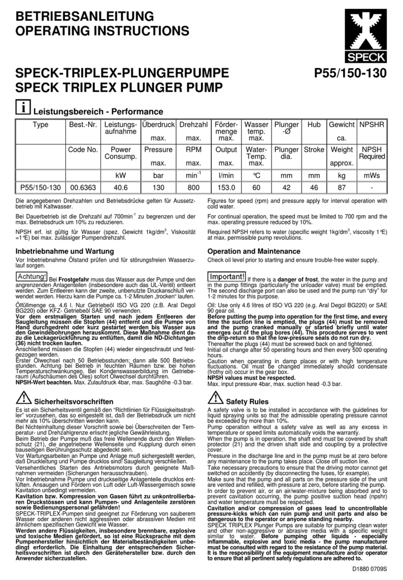
Speck P55/150-130 User manual

Speck

Speck P55/150-130 User manual

Speck P55/150-130G User manual

Speck

Speck P55/150-130G User manual

Speck P52/22-600 User manual

Speck

Speck P52/22-600 User manual

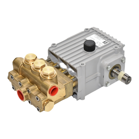
Speck Triplex NP25 Series User manual

Speck

Speck Triplex NP25 Series User manual

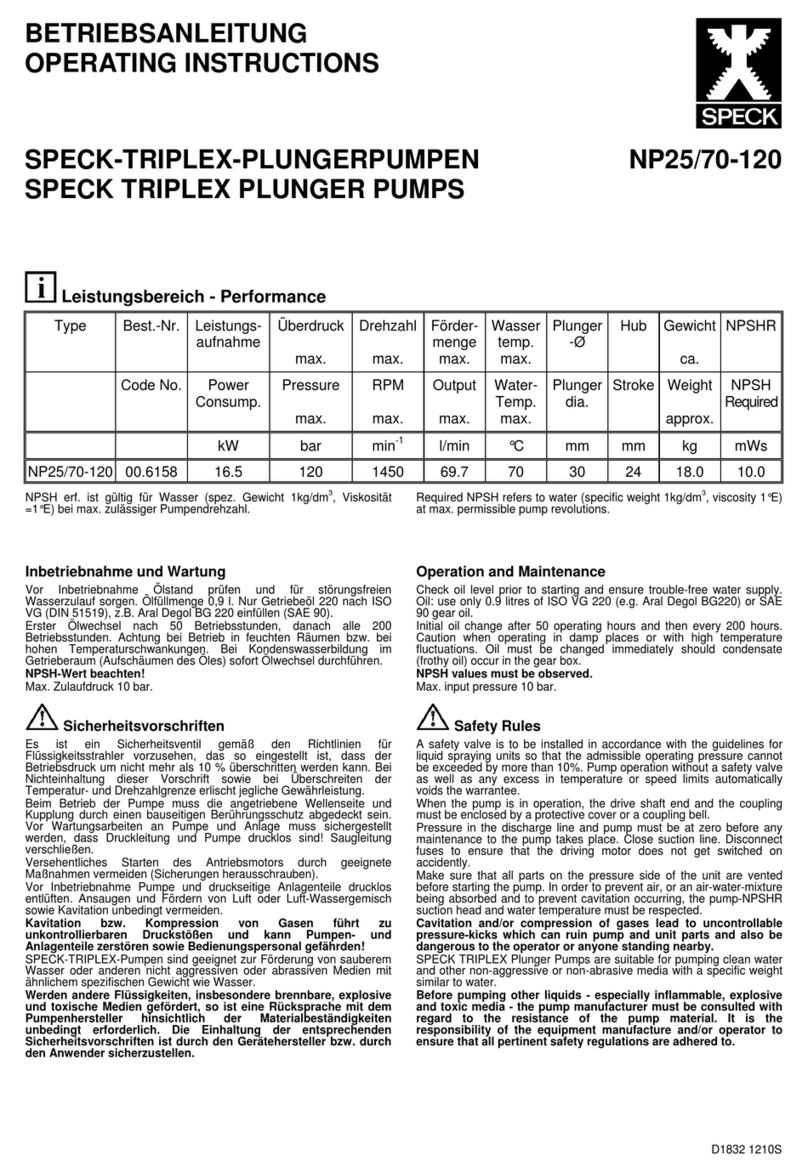
Speck NP25/70-120 User manual

Speck

Speck NP25/70-120 User manual

Speck BS15 Guide

Speck

Speck BS15 Guide

Speck 72 User manual

Speck

Speck 72 User manual

Speck Normblock Multi 65/250 User manual

Speck

Speck Normblock Multi 65/250 User manual

Speck P55/165-100 User manual

Speck

Speck P55/165-100 User manual

Speck P30 User manual

Speck

Speck P30 User manual

Speck P22/15-280 User manual

Speck

Speck P22/15-280 User manual

Speck Triplex P52/40-400MS User manual

Speck

Speck Triplex P52/40-400MS User manual

Speck NP30/90-150 User manual

Speck

Speck NP30/90-150 User manual

Speck BADU 93 Series Parts list manual

Speck

Speck BADU 93 Series Parts list manual

Speck P30/36-150RED User manual

Speck

Speck P30/36-150RED User manual

Speck P52 User manual

Speck

Speck P52 User manual

Speck NP25/70-100 User manual

Speck

Speck NP25/70-100 User manual

Speck Badu Stream II Operation manual

Speck

Speck Badu Stream II Operation manual

Speck P52/30-500MS User manual

Speck

Speck P52/30-500MS User manual

Speck BADU Owner's manual

Speck

Speck BADU Owner's manual

Speck P71/250-100RDK User manual

Speck

Speck P71/250-100RDK User manual

Speck P22/28-100 User manual

Speck

Speck P22/28-100 User manual

Popular Water Pump manuals by other brands

GORMAN-RUPP PUMPS GMC Series Installation, operation and maintenance manual

GORMAN-RUPP PUMPS

GORMAN-RUPP PUMPS GMC Series Installation, operation and maintenance manual

EINHELL HOME GH-SP 2768 Original operating instructions

EINHELL HOME

EINHELL HOME GH-SP 2768 Original operating instructions

Vogt AM Series Service manual

Vogt

Vogt AM Series Service manual

Bluefin SUP Electric iSUP Air Pump instruction manual

Bluefin SUP

Bluefin SUP Electric iSUP Air Pump instruction manual

Wilo Rexa PRO Series Installation and operating instructions

Wilo

Wilo Rexa PRO Series Installation and operating instructions

BUSCH COBRA DS 0080-2000 G instruction manual

BUSCH

BUSCH COBRA DS 0080-2000 G instruction manual

Lincoln FlowMaster C Series manual

Lincoln

Lincoln FlowMaster C Series manual

Tronair 06-5024 Series Operation & service manual

Tronair

Tronair 06-5024 Series Operation & service manual

Becker T 4.16 DV operating instructions

Becker

Becker T 4.16 DV operating instructions

WITA Delta Top 60 Series Installation and operating instructions

WITA

WITA Delta Top 60 Series Installation and operating instructions

ITT Goulds Pumps SRL Installation, operation and maintenance manual

ITT

ITT Goulds Pumps SRL Installation, operation and maintenance manual

Pentair UV3 instruction manual

Pentair

Pentair UV3 instruction manual

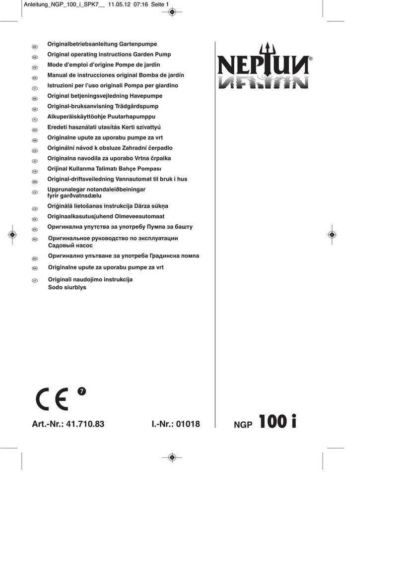
Grundfos Unilift KP 150 Installation and operating instructions

Grundfos

Grundfos Unilift KP 150 Installation and operating instructions

GORMAN-RUPP PUMPS SUPER T T6A60S-4LE2X FT4 Series Installation, operation, and maintenance manual with parts list

GORMAN-RUPP PUMPS

GORMAN-RUPP PUMPS SUPER T T6A60S-4LE2X FT4 Series Installation, operation, and maintenance manual with parts list

Federal Pump BGP Series Installation, operation & maintenance manual

Federal Pump

Federal Pump BGP Series Installation, operation & maintenance manual

Regulus CSE TVMIX ZV G 3/4M Installation and operation manual

Regulus

Regulus CSE TVMIX ZV G 3/4M Installation and operation manual

Aquascape Pro AquaSurge PRO 2000-4000 Instructions & maintenance

Aquascape Pro

Aquascape Pro AquaSurge PRO 2000-4000 Instructions & maintenance

GORMAN-RUPP PUMPS 80 Series Installation, operation and maintenance manual

GORMAN-RUPP PUMPS

GORMAN-RUPP PUMPS 80 Series Installation, operation and maintenance manual

manuals.online logo
manuals.online logoBrands
  • About & Mission
  • Contact us
  • Privacy Policy
  • Terms and Conditions

Copyright 2025 Manuals.Online. All Rights Reserved.