Staubli MA251 User manual

1/12
PV-CZM...
* UL le E343181
MA251 (de_en)
Bedienungsanleitung
MA251 (de_en)
Operating instructions
Crimpzange PV-CZM...
für MC3, MC4 und MC4-EVO 2
Crimping pliers PV-CZM...
for MC3, MC4 and MC4-EVO 2
Inhalt
Sicherheitshinweise....................................................................2
Ausführung für MC3..................................................................3
Ausführung für MC4..................................................................4
Ausführung für MC4-EVO 2 ......................................................5
Crimp-Einsatz auswechseln.......................................................7
— Crimp-Einsatz ausbauen ........................................................7
— Crimp-Einsatz einbauen .........................................................7
Crimpen.....................................................................................8
Crimpqualität .............................................................................9
Notizen ...............................................................................10-12
Content
Safety Instructions......................................................................2
Explanation for MC3..................................................................3
Explanation for MC4..................................................................4
Explanation for MC4-EVO 2 ......................................................5
Exchanging the crimping insert.................................................7
— Removing the crimping insert................................................7
— Fitting the crimping insert......................................................7
Crimping....................................................................................8
Crimping quality ........................................................................9
Notes ..................................................................................10-12

2/12
Sicherheitshinweise Safety Instructions
Die Montage und Installation der Produkte darf ausschliess-
lich durch qualiziertes und erfahrenes Fachpersonal unter
Berücksichtigung aller anwendbaren gesetzlichen Sicher-
heitsbestimmungen und Regelungen erfolgen. Stäubli Electri-
cal Connectors (Stäubli) lehnt jegliche Haftung infolge Nicht-
einhaltung dieser Warnhinweise ab.
The products may be assembled and installed exclusively by
suitably qualied and trained specialists duly observing all ap-
plicable safety regulations.
Stäubli Electrical Connectors (Stäubli) does not accept any li-
ability in the event of failure to observe these warnings.
Benutzen Sie nur die von Stäubli angegebenen Einzelteile und
Werkzeuge. Weichen Sie nicht von den hier beschriebenen
Vorgängen zur Vorbereitung und Montage ab, da sonst bei der
Selbstkonfektionierung weder die Sicherheit noch die Einhal-
tung der technischen Daten gewährleistet ist. Ändern Sie das
Produkt nicht in irgend einer Weise ab.
Use only the components and tools specied by Stäubli. In
case of self-assembly, do not deviate from the preparation
and assembly instructions as stated herein, otherwise Stäubli
cannot give any guarantee as to safety or conformity with the
technical data. Do not modify the product in any way.
Die hier beschriebenen Arbeiten dürfen nicht an
stromführenden oder unter Spannung stehenden
Teilen durchgeführt werden.
The work described here must not be carried out
on live or load-carrying parts.
Der Schutz vor einem elektrischen Schlag muss
durch das Endprodukt (d.h. dem korrekt kongu-
rierten Steckverbinder) gegeben sein und vom An-
wender selbst sichergestellt werden.
Protection from electric shock must be assured by
the end product (i.e. by the correctly assembled
plug connector) and by its user.
Stäubli empehlt aus Sicherheitsgründen dringend,
weder PVC-Kabel noch unverzinnte Kabel vom Typ
H07RN-F zu verwenden.
For safety reasons, Stäubli does strongly recom-
mend not to use PVC cables or untinned cables of
type H07RN-F.
Weitere technische Daten entnehmen Sie bitte dem
Produktkatalog.
For further technical data please see the product
catalogue.
Erklärung der Symbole Explanation of the symbols
Warnung vor gefährlicher elektrischer Spannung Warning of dangerous voltages
Warnung vor einer Gefahrenstelle Warning of a hazard area
Nützlicher Hinweis oder Tipp Useful hint or tip

3 / 12
1
2
3
45
4
Ausführung für MC3 Explanation for MC3
(ill. 1)
Crimpzange PV-CZM-16100A
inkl. zwei auswechselbaren Locators
und zwei auswechselbaren Crimp-
Einsätzen
(ill. 1)
Crimping pliers PV-CZM-16100A
incl. two interchangeable Locators
and two interchangeable crimping
inserts
Crimpbereich: 2,5 / 4 / 6mm2
(14 / 12 / 10AWG)
Bestell-Nr.: 32.6020-16100A
Crimping range: 2,5 / 4 / 6mm2
(14 / 12 / 10AWG)
Order No.: 32.6020-16100A
Einzelteile Individual parts
(ill. 2 + 3)
Auswechselbare Crimp-Einsätze
(ill. 2 + 3)
Interchangeable crimping inserts
Crimpbereich
Crimping range
Ty p
Type
Bestell-Nr.
Order No.
mm2AWG
2,5 / 4 / 6 14 / 12 / 10 PV-ES-CZM-16100 32.6021-16100
4 / 10 PV-ES-CZM-17100 32.6021-17100
(ill. 4)
Auswechselbare Locators
(ill. 4)
Interchangeable locators
Crimpbereich
Crimping range
Ty p
Type
Bestell-Nr.
Order No.
mm2AWG
2,5 / 4 / 6 12/10 PV-LOC-A 32.6039
4 / 10 PV-LOC-A10 32.6049
Diese Locatortypen sind nur für
Ø 3mm.
This locator types are for Ø 3mm only
Pos. Leiterquerschnitt
Cable cross section
geeignet für
suitable for
mm2AWG
4410 PV-SP3/4
PV-BP3/4
510 PV-SP4/10
PV-BP4/10
Pos. Leiterquerschnitt
Cable cross section
geeignet für
suitable for
mm2AWG
12,5 14 PV-SP3/4
PV-BP3/4
2412 PV-SP3/4
PV-BP3/4
36PV-SP3/6
PV-BP3/6

4 / 12
5
12
3
5
4
6
8
7
6
7
8
Ausführung für MC4 Explanation for MC4
(ill. 5)
Crimpzange inkl. Locator PV-LOC und
eingebautem Crimp-Einsatz
(ill. 5)
Crimping pliers incl. locator PV-LOC
and built-in crimping insert
Crimpbereich: 1,5 / 2,5 / 4mm2
(14 / 12AWG)
Typ: PV-CZM-18100
Bestell-Nr.: 32.6020-18100
Crimping range: 1,5 / 2,5 / 4mm2
(14 / 12AWG)
Type: PV-CZM-18100
Order No.: 32.6020-18100
Crimpbereich: 2,5 / 4 / 6mm2
(12 / 10AWG)
Typ: PV-CZM-19100
Bestell-Nr.: 32.6020-19100
Crimping range: 2,5 / 4 / 6mm2
(12 / 10AWG)
Type: PV-CZM-19100
Order No.: 32.6020-19100
Crimpbereich: 4 / 10mm2
Typ: PV-CZM-20100
Bestell-Nr.: 32.6020-20100
Crimping range: 4 / 10mm2
Type: PV-CZM-20100
Order No.: 32.6020-20100
Crimpbereich: 6 / 10mm2
Typ: PV-CZM-21100
Bestell-Nr.: 32.6020-21100
Crimping range: 6 / 10mm2
Type: PV-CZM-21100
Order No.: 32.6020-21100
Crimpbereich: 8 / 12 / 10AWG
Typ: PV-CZM-22100
Bestell-Nr.: 32.6020.22100
Crimping range: 8 / 12 / 10AWG
Type: PV-CZM-22100
Order No.: 32.6020-22100
Einzelteile Individual parts
(ill. 6 + 7 + 8 + 9 + 10)
Auswechselbare Crimp-Einsätze
(ill. 6 + 7 + 8 + 9 + 10)
Interchangeable crimping inserts
Crimpbereich
Crimping range
Ty p
Type
Bestell-Nr.
Order No.
mm2AWG
1,5 / 2,5 / 4 14 / 12 PV-ES-CZM-18100 32.6021-18100
Crimpbereich
Crimping range
Ty p
Type
Bestell-Nr.
Order No.
mm2AWG
2,5 / 4 / 6 12/10 PV-ES-CZM-19100 32.6021-19100
Crimpbereich
Crimping range
Ty p
Type
Bestell-Nr.
Order No.
mm2AWG
4 / 10 PV-ES-CZM-20100 32.6021-20100
Pos. Leiterquerschnitt
Cable cross section
geeignet für
suitable for
mm2AWG
11,5 14 PV-SP4/2.5
PV-BP4/2.5
22,5 PV-SP4/2.5
PV-BP4/2.5
3412 PV-SP4/6
PV-BP4/6
Pos. Leiterquerschnitt
Cable cross section
geeignet für
suitable for
mm2AWG
42,5 PV-SP4/2.5
PV-BP4/2.5
5412 PV-SP4/6
PV-BP4/6
6610 PV-SP4/6
PV-BP4/6
Pos. Leiterquerschnitt
Cable cross section
geeignet für
suitable for
mm2
74PV-SP4/6
PV-BP4/6
810 PV-SP4/10
PV-BP4/10

5/12
9
10
9
11
11
12
13 10
12
Crimpbereich
Crimping range
Ty p
Type
Bestell-Nr.
Order No.
mm2
6 / 10 PV-ES-CZM-21100 32.6021-21100
Crimpbereich
Crimping range
Ty p
Type
Bestell-Nr.
Order No.
AWG
8 / 12 / 10 PV-CZM-22100 32.6020.22100
(ill. 11)
Locator PV-LOC
Bestell-Nr.: 32.6040
Locator PV-LOC-B
Bestell-Nr.: 32.6055
Hinweis:
Beim Einsatz des Crimpwerk-
zeuges PV-CZM-22100 benutzen
Sie bitte den Locator PV-LOC-B.
(ill. 11)
Locator PV-LOC
Order No.: 32.6040
Locator PV-LOC-B
Order No.: 32.6055
Note:
When using the crimping tool
PV-CZM-22100, please use the
locator PV-LOC-B.
Ausführung für MC4-EVO 2 Explanation for MC4-EVO 2
(ill. 12)
Crimpzange inkl. Locator und einge-
bautem Crimpeinsatz
(ill. 12)
Crimping pliers incl. Locator and built
in crimping insert
Crimpbereich: 1,5 / 2,5 / 4mm2
(14 / 12AWG)
Typ: PV-CZM-40100
Bestell-Nr.: 32.6020-40100
Crimping range: 1,5 / 2,5 / 4mm2
(14 / 12AWG)
Type: PV-CZM-40100
Order No.: 32.6020-40100
Crimpbereich: 2,5 / 4 / 6mm2
(14 / 12 / 10AWG)
Typ: PV-CZM-41100
Bestell-Nr.: 32.6020-41100
Crimping range: 2,5 / 4 / 6mm2
(14 / 12 / 10AWG)
Type: PV-CZM-41100
Order No.: 32.6020-41100
Crimpbereich: 4 / 10mm2
(12 / 8AWG)
Typ: PV-CZM-42100
Bestell-Nr.: 32.6020-42100
Crimping range: 4 / 10mm2
(12 / 8AWG)
Type: PV-CZM-42100
Order No.: 32.6020-42100
Pos. Leiterquerschnitt
Cable cross section
geeignet für
suitable for
mm2
96PV-SP4/6
PV-BP4/6
10 10 PV-SP4/10
PV-BP4/10
Pos. Leiterquerschnitt
Cable cross section
geeignet für
suitable for
AWG
11 8PV-SP4/8
PV-BP4/8
12 10 PV-SP4/6
PV-BP4/6
13 12 PV-SP4/6
PV-BP4/6

6 / 12
13
14
15
16
2
1
3
5
4
6
7
8
Einzelteile Individual parts
(ill. 13 + 14 + 15)
Auswechselbare Crimpeinsätze
(ill. 13 + 14 + 15)
Interchangeable crimping inserts
Crimpbereich
Crimping range
Ty p
Type
Bestell-Nr.
Order No.
mm2AWG
1,5 / 2,5 / 4 14 / 12 PV-ES-CZM-40100 32.6021-40100
Crimpbereich
Crimping range
Ty p
Type
Bestell-Nr.
Order No.
mm2AWG
2,5 / 4 / 6 14 / 12 / 10 PV-ES-CZM-41100 32.6021-41100
Crimpbereich
Crimping range
Ty p
Type
Bestell-Nr.
Order No.
mm2AWG
4 / 10 12 / 8 PV-ES-CZM-42100 32.6021-42100
(ill. 16)
Locator PV-LOC-C
Bestell-Nr.: 32.6056
(ill. 16)
Locator PV-LOC-C
Order no.: 32.6056
Pos. Leiterquerschnitt
Cable cross section
geeignet für
suitable for
mm2AWG
11,5 PV-SP4-EVO 2/2,5
PV-BP4-EVO 2/2,5
22,5 14 PV-SP4-EVO 2/2,5
PV-BP4-EVO 2/2,5
3412 PV-SP4-EVO 2/6
PV-BP4-EVO 2/6
Pos. Leiterquerschnitt
Cable cross section
geeignet für
suitable for
mm2AWG
42,5 14 PV-SP4-EVO 2/2,5
PV-BP4-EVO 2/2,5
5412 PV-SP4-EVO 2/6
PV-BP4-EVO 2/6
6610 PV-SP4-EVO 2/6
PV-BP4-EVO 2/6
Pos. Leiterquerschnitt
Cable cross section
geeignet für
suitable for
mm2AWG
7412 PV-SP4-EVO 2/6
PV-BP4-EVO 2/6
810 8PV-SP4-EVO 2/10
PV-BP4-EVO 2/10

7/12
21
22
19
20
17
18
Crimp-Einsatz einbauen Fitting the crimping insert
(ill. 21)
Öffnen Sie die Crimpzange (ganz zu-
sammendrücken und loslassen).
Führen Sie beide Crimp-Einsätze ein.
Die Beschriftung muss auf der glei-
chen Seite sein wie die Beschriftung
der Crimpzange.
Schliessen Sie die Crimpzange und
schrauben Sie beide Crimp-Einsätze
fest.
(ill. 21)
Open the crimping tool (press com-
pletely together and release). Insert
both crimping inserts. The markings
must be on the same side as the
marking on the crimping tool.
Close crimping tool and screw both
crimping inserts tight.
(ill. 22)
Legen Sie den Locator in den Füh-
rungsstift ein.
(ill. 22)
Insert locator into the guide pin.
Crimp-Einsatz auswechseln Exchanging the crimping
inserts
Crimp-Einsatz ausbauen Removing the crimping insert
(ill. 17)
Schliessen Sie die Crimpzange
(ill. 17)
Close the crimping tool
(ill. 18)
Drehen Sie die Schraube S (lang)
und S1 (kurz) heraus. Öffnen Sie die
Crimpzange (ganz zusammendrücken
und loslassen).
(ill. 18)
Unscrew both the long S and the
short S1 screw. Open the crimping
tool (press completely together and
release).
(ill. 19)
Oberen Crimp-Einsatz herausnehmen.
(ill. 19)
Remove the upper crimping insert.
(ill. 20)
Unteren Crimp-Einsatz herausneh-
men.
(ill. 20)
Remove the lower crimping insert.
8 / 12
25
26
23
24
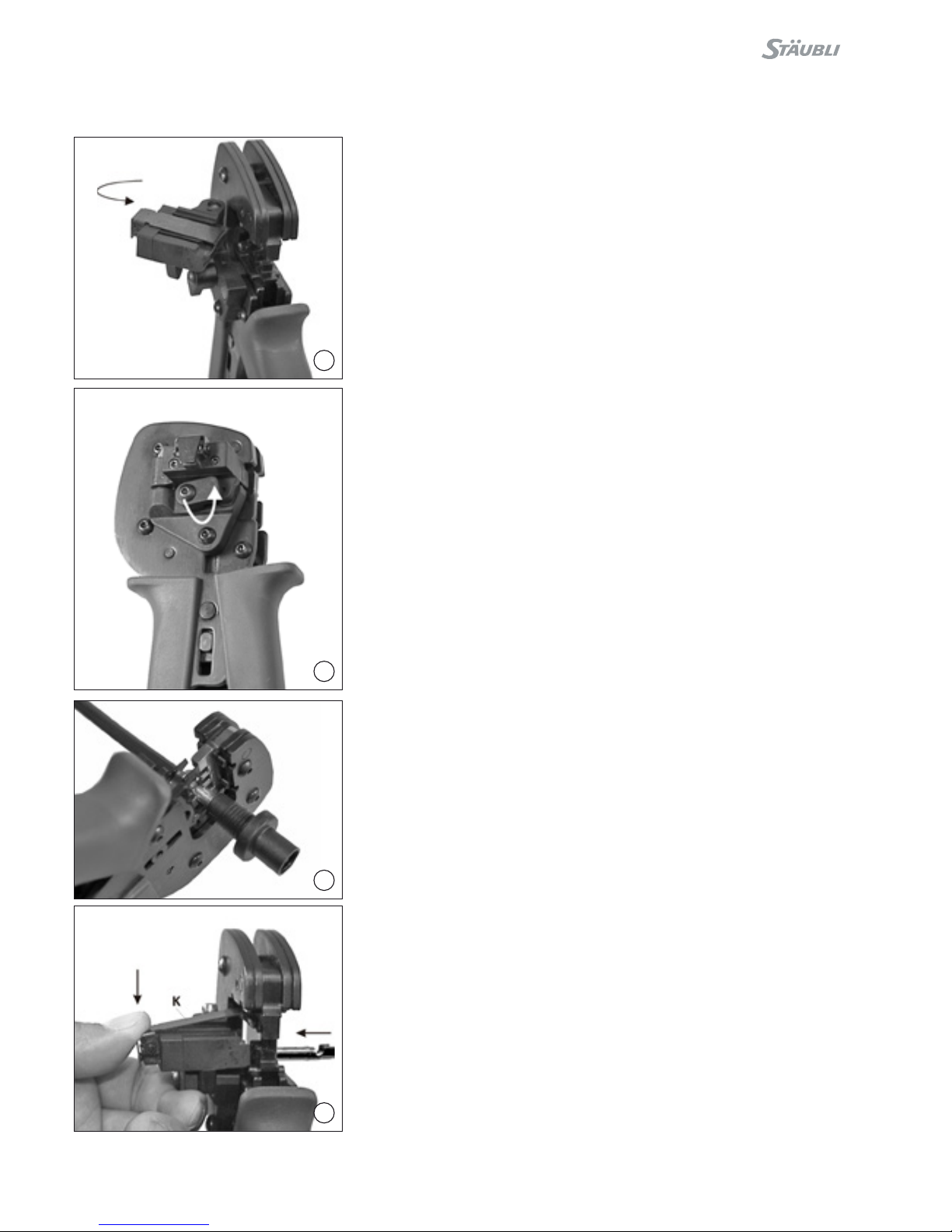
(ill. 23)
Schwenken Sie den Locator um (wird
magnetisch festgehalten).
(ill. 23)
Rotate the locator (held magnetically)
(ill. 24)
Verriegeln Sie den Locator.
(ill. 24)
Lock the locator.
Crimpen Crimping
Beispiel ADBP3/... und ADSP3/... Example for ADBP3/... and
ADSP3/...
(ill. 25)
Entfernen Sie den Locator. Führen Sie
das abisolierte Kabel links ein, bis die
Isolation am Crimp-Einsatz anschlägt.
Legen Sie den Kontakt ein und
schliessen Sie die Crimpzange ganz.
Kontrollieren Sie die Vercrimpung
visuell (siehe ill. 23).
(ill. 25)
Remove the locator. Insert the
stripped cable on the left side until the
insulation comes into contact with the
crimping insert. Close crimping tool
completely.
Check crimp (see ill. 23).
Beispiel KBT4.../KST4... Example for KBT4.../KST4...
(ill. 26)
Öffnen Sie den Klemmbügel K und
halten Sie ihn fest. Legen Sie den Kon-
takt in den passenden Querschnitts-
bereich. Drehen Sie die Crimplaschen
nach oben. Lassen Sie den Klemmbü-
gel K los. Der Kontakt ist xiert.
(ill. 26)
Open and hold clamping clip K. Insert
contact in the appropriate cross-sec-
tion range of the crimping tool. Turn
contact till crimping tabs face the top.
Release clamping clip K. The contact
is secured.

9/12
29
27
28
(ill. 27)
Drücken Sie die Zange leicht zusam-
men, bis die Crimplaschen sicher
innerhalb der Crimp-Matritze liegen.
(ill. 27)
Lightly press the pliers together so
that the crimping tabs lie securely
within the crimping die.
(ill. 28)
Führen Sie das abisolierte Kabel ein,
bis die Leiter am Klemmbügel an-
schlagen. Schliessen Sie die Crimp-
zange ganz.
(ill. 28)
Insert the stripped cable until the
strands touch the clamping bracket.
Completely close the crimping pliers.
Crimpqualität Crimping quality
Mit der Crimphöhe lässt sich die Qua-
lität der Crimpung beurteilen. Typische
Werte für die Kabel FLEX-SOL-XL und
Studer BETAam® entnehmen sie bitte
aus der folgenden Tabelle.
The quality of the crimp can be as-
sessed on the basis of the crimp
height. Typical values for the cables
FLEX-SOL-XL and Studer BETAam®
are shown in the following table.
(ill. 29)
Kontrollieren Sie die Vercrimpung
visuell.
(ill. 29)
Visually check the crimp.
AKabel
Cable
Crimphöhe
Crimp height
mm2mm
1,5 FLEX-SOL-XL
BETAam®1,65
1,65
2,5 FLEX-SOL-XL
BETAam®1,80
1,80
4FLEX-SOL-XL
BETAam®2,15
2,15
6FLEX-SOL-XL
BETAam®2,40
2,40
10 FLEX-SOL-XL 3,02
MC4 / MC4-EVO 2
AKabel
Cable
Crimphöhe
Crimp height
mm2mm
1,5 FLEX-SOL-XL
BETAam®2,20
2,20
2,5 FLEX-SOL-XL
BETAam®2,20
2,20
4FLEX-SOL-XL
BETAam®2,50
2,50
6FLEX-SOL-XL
BETAam®3,12
3,12
10 FLEX-SOL-XL 4,80
MC3

10/12
Notizen / Notes:

11/12
Notizen / Notes:

12/12
Hersteller/Producer:
Stäubli Electrical Connectors AG
Stockbrunnenrain 8
4123 Allschwil/Switzerland
Tel. +41 61 306 55 55
Fax +41 61 306 55 56
www.staubli.com/electrical
© by Stäubli Electrical Connectors AG, Switzerland – MA251 – 01.2017, Index a, Marketing Communications – Änderungen vorbehalten / Subject to alterations
Notizen / Notes:
Other manuals for MA251
7
Table of contents
Other Staubli Power Tools manuals

Staubli
Staubli M-PZ-T2600 User manual

Staubli
Staubli M-PZ-T2600 User manual

Staubli
Staubli MA251 User manual

Staubli
Staubli MA224 User manual

Staubli
Staubli M-PZ13 User manual

Staubli
Staubli M-PZ-T2600 User manual

Staubli
Staubli PV-MS-PLS User manual

Staubli
Staubli PV-MS-PLS User manual

Staubli
Staubli MA251 User manual

Staubli
Staubli MA251 User manual

Staubli
Staubli PV-MS-PLS User manual

Staubli
Staubli MA251 User manual

Staubli
Staubli M-PZ13 User manual

Staubli
Staubli PV-CZM-BS User manual

Staubli
Staubli PV-AZM User manual

Staubli
Staubli M-PZ13 User manual

Staubli
Staubli CTD-M-CZ User manual

Staubli
Staubli MA251 User manual

Staubli
Staubli MA251 User manual


