manuals.online logo
Brands
  1. Home
  2. •
  3. Brands
  4. •
  5. Staubli
  6. •
  7. Power Tools
  8. •
  9. Staubli CTD-M-CZ User manual

Staubli CTD-M-CZ User manual

1 / 4
MES-CZ-CTD1 MES-CZ-CTD1,5 MES-CZ-CTD3
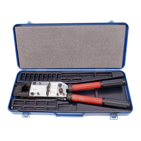
CTD-M-CZ
MA076 (de_en)
Montageanleitung
MA076 (de_en)
Assembly instructions
MA419 (fr_en)
Notice d‘utilisation
MA419 (fr_en)
Operating instructions
Pince à sertir CTD-M-CZ Crimping pliers CTD-M-CZ
Sommaire
Consignes de sécurité �����������������������������������������������������������������2
Fonctionnement����������������������������������������������������������������������� 3-4
Content
Safety Instructions �����������������������������������������������������������������������2
Operating �������������������������������������������������������������������������������� 3-4
Type No. de Cde.
Order No. Description
Section du conducteur
Cable cross section
mm² AWG
CTD-M-CZ 33.3900 Pince à sertir
Crimping pliers
MES-CZ-CTD1 33.3910 Positionneur
Locator
0,14 26
0,25 24
0,5 20
0,75 18
MES-CZ-CTD1,5 33.3911 Positionneur
Locator
0,75 18
1 18
1,5 16
MES-CZ-CTD3 33.3912 Positionneur
Locator
2,5 14
4 12
2 / 4
Consignes de sécurité Safety instructions
Utiliser uniquement les pièces et les outils recommandés par
Stäubli puis suivre scrupuleusement les étapes de préparation et
de montage décrites ci-dessous� Le cas échéant, ni la sécurité ni
le respect des caractéristiques techniques ne sont garantis par
Stäubli� Ne modifier le produit d’aucune manière�
Use only the components and tools specified by Stäubli� In case
of self-assembly, do not deviate from the preparation and assem-
bly instructions as stated herein, otherwise Stäubli cannot give
any guarantee as to safety or conformity with the technical data�
Do not modify the product in any way�
Les connecteurs non fabriqués par Stäubli, parfois qualifiés de
« compatibles Stäubli » par certains fabricants et enfichables avec
des éléments Stäubli, ne répondent pas aux exigences d’une
liaison électrique sûre et stable à long terme� Pour des raisons
de sécurité, ils ne doivent pas être enfichés dans des éléments
Stäubli� Par conséquent, nous déclinons toute responsabilité si
ces connecteurs non approuvés par Stäubli sont utilisés avec
des éléments Stäubli et que des dommages en résultent�
Connectors not originally manufactured by Stäubli which can be
mated with Stäubli elements and in some cases are even de-
scribed as ”Stäubli-compatible” by certain manufacturers do not
conform to the requirements for safe electrical connection with
long-term stability, and for safety reasons must not be plugged
together with Stäubli elements� Stäubli therefore does not ac-
cept any liability for any damages resulting from mating such
connectors (i�e� lacking Stäubli approval) with Stäubli elements�
Stäubli Electrical Connectors (Stäubli) décline toute responsabil-
ité en cas de non-respect de ces consignes�
Stäubli Electrical Connectors (Stäubli) does not accept any
liability in the event of failure to observe these warnings�
IEC 60417-6182
Installation, expertise électrotechnique Installation, electrotechnical expertise
Le montage et l’installation des produits ne doivent être eectués
que par du personnel qualifié et formé en respectant toutes les
dispositions de sécurité et les réglementations légales applica-
bles�
The products may be assembled and installed by electrically
skilled or instructed persons duly observing all applicable safety
regulations�
IEC 60417-6042
Danger, risque d‘électrocution Caution, risk of electric shock
Travailler hors tension
Respecter les cinq règles de sécurité relatives au travail sur des
installations électriques�
Après identification des installations électriques correspondan-
tes, les cinq exigences essentielles suivantes doivent être appli-
quées dans l‘ordre spécifié à moins qu‘il y ait des raisons essen-
tielles pour faire autrement:
■déconnecter complètement;
■sécuriser contre la réalimentation;
■Vérifier l‘absence de tension de service;
■Mettre à la terre et en court-circuit;
■Mettre hors de portée les pièces nues voisines restant sous
tension�
Toute personne participant à ces travaux doit être qualifiée ou
avertie, ou doit être surveillée par une telle personne�
Source: EN 50110-1:2013 (DIN EN 50110-1, VDE 0105-1)
Work in a de-energized state
Follow the five safety rules, when working on electrical installa-
tions�
After the respective electrical installations have been identified,
the following five essential requirements shall be undertaken in
the specified order unless there are essential reasons for doing
otherwise:
■disconnect completely;
■secure against re-connection;
■verify absence of operating voltage;
■carry out grounding and short-circuiting;
■provide protection against adjacent live parts�
Any person engaged in this work activity shall be electrically
skilled or instructed, or shall be supervised by such a person�
Source: EN 50110-1:2013
La protection contre les chocs électriques doit également être
vérifiée pour l‘ensemble des équipements de l‘application finale�
Protection against electric shock shall be checked in the end-use
applications too�
ISO 7000-0434B
Attention Caution
Avant chaque utilisation, vérifier auparavant l’absence de tout dé-
faut externe (et en particulier l’isolation)� En cas de doute concer-
nant la sécurité du matériel, faire appel à un expert ou procéder
au remplacement du connecteur incriminé�
Each time the connector is used, it should previously be inspect-
ed for external defects (particularly the insulation)� If there are any
safety concerns, a specialist must be consulted or the connector
must be replaced�
Remarque ou conseil utile Useful hint or tip
Pour les caractéristiques techniques détaillées, se reporter au
catalogue des produits, www�staubli�com/electrical
For further technical data please see the product catalog,
www�staubli�com/electrical
3 / 4
1
2
(ill. 1)
Sélectionner le positionneur�
■Installer le positionneur dans la pince
■Mettre la vis coulissante en position
■Serrer la vis
(ill. 1)
Select the locator�
■Install the locator in the pliers
■Move the slide screw into position
■Tighten it
Matrice / Die
Echelle / Scale
Plage du sélecteur / Selector range
Vis coulissante / Slide screw
(ill. 2)
Régler le sélecteur
(ill. 2)
Set the selector�
Remarque:
Utiliser l’échelle «M22520/1-01»�
Note:
Use scale “M22520/1-01”!
4 / 4
4
3
Fabricant/Producer:
Stäubli Electrical Connectors AG
Stockbrunnenrain 8
4123 Allschwil/Switzerland
Tel. +41 61 306 55 55
Fax +41 61 306 55 56
mail [email protected]
www.staubli.com/electrical
© by Stäubli Electrical Connectors AG, Switzerland – MA419 – 07.2020, Index a, Marketing Communications – Modifications sous réserve / Subject to alterations
(ill.3)
Insérer le fût à sertir dans la pince� Fermer et fixer�
(ill. 3)
Insert the crimping sleeve into the pliers� Close until fixed�
(ill.4)
■Introduire axialement le conducteur dans le fût à sertir jusqu’en
butée�
(ill. 4)
■Insert the wire in the crimping sleeve as far as possible
Remarque:
(Pour les contacts de Ø nominal de 1mm, 1,5mm et
3mm)� Le conducteur doit être visible dans l’orifice de contrôle
avant et après le sertissage�
Note:
(For contacts with nominal Ø 1mm, 1,5mm and 3mm)�

Inserted wires must be visible through the sight hole, before and
after crimping�
■Fermer complètement la pince�
■La pince se relâche automatiquement�
■Close the pliers completely�
■The pliers release automatically�
Remarque:
Lorsque le processus de sertissage a commencé, il ne peut
pas être interrompu� La pince à sertir ne peut être relâchée
qu’une fois le processus de sertissage terminé�
Note:
Once the crimping process has started, it cannot be in-
terrupted� The crimping pliers can only be released once the
crimping process is complete�
Remarque:
Fermer délicatement la pince pour la verrouiller�
Note:
Slightly close the pliers to lock!
Positionnement de la pince à sertir indent 4/8 (fût
de sertissage fermé):
Positioning of the 4/8 indent crimping pliers
(closed crimp barrel):
L’indent doit être placé entre le bord du fût de sertissage et l’ex-
trémité du regard� Le positionnement optimal consiste à installer
l’indent entre le bord du fût de sertissage et l’ouverture du regard�
The indent must be placed between the edge of the crimp barrel
and the end of the sight hole� The optimal positioning is centered
between the edge of the crimp barrel and the beginning of the
sight hole�
Pour plus d’informations et des consignes de maintenance, voir
également les instructions du fabricant�
For information and maintenance, see also the manufacturer
instructions�

Other Staubli Power Tools manuals

Staubli MA251 User manual

Staubli

Staubli MA251 User manual

Staubli MA251 User manual

Staubli

Staubli MA251 User manual

Staubli MA251 User manual

Staubli

Staubli MA251 User manual

Staubli M-PZ13 User manual

Staubli

Staubli M-PZ13 User manual

Staubli PV-AZM User manual

Staubli

Staubli PV-AZM User manual

Staubli M-PZ-T2600 User manual

Staubli

Staubli M-PZ-T2600 User manual

Staubli M-PZ13 User manual

Staubli

Staubli M-PZ13 User manual

Staubli PV-MS-PLS User manual

Staubli

Staubli PV-MS-PLS User manual

Staubli MA224 User manual

Staubli

Staubli MA224 User manual

Staubli PV-MS-PLS User manual

Staubli

Staubli PV-MS-PLS User manual

Staubli MA251 User manual

Staubli

Staubli MA251 User manual

Staubli M-PZ-T2600 User manual

Staubli

Staubli M-PZ-T2600 User manual

Staubli MA251 User manual

Staubli

Staubli MA251 User manual

Staubli M-PZ13 User manual

Staubli

Staubli M-PZ13 User manual

Staubli MA251 User manual

Staubli

Staubli MA251 User manual

Staubli MA251 User manual

Staubli

Staubli MA251 User manual

Staubli PV-CZM-BS User manual

Staubli

Staubli PV-CZM-BS User manual

Staubli M-PZ-T2600 User manual

Staubli

Staubli M-PZ-T2600 User manual

Staubli PV-MS-PLS User manual

Staubli

Staubli PV-MS-PLS User manual

Popular Power Tools manuals by other brands

Taylor T-2XS manual

Taylor

Taylor T-2XS manual

Baileigh Industrial DP-1400VS Operator's manual

Baileigh Industrial

Baileigh Industrial DP-1400VS Operator's manual

FAR KJ28 operating instructions

FAR

FAR KJ28 operating instructions

SCHUNK PWG-S 40 Assembly and operating manual

SCHUNK

SCHUNK PWG-S 40 Assembly and operating manual

Gedore KL-1000-20 A instruction manual

Gedore

Gedore KL-1000-20 A instruction manual

Makita HR001G instruction manual

Makita

Makita HR001G instruction manual

Parkside PMFW 310 C2 Translation of the original instructions

Parkside

Parkside PMFW 310 C2 Translation of the original instructions

Ferm TDM1027 Original instructions

Ferm

Ferm TDM1027 Original instructions

Micron MC-20 user manual

Micron

Micron MC-20 user manual

REMS Mini-Amigo operating instructions

REMS

REMS Mini-Amigo operating instructions

Titan LX-70 owner's manual

Titan

Titan LX-70 owner's manual

HYPERVIBE G17 PRO owner's manual

HYPERVIBE

HYPERVIBE G17 PRO owner's manual

3M 10800 Instructions and parts list

3M

3M 10800 Instructions and parts list

ITW SuperFlow Safety & Operation Instructions

ITW

ITW SuperFlow Safety & Operation Instructions

Makita 9820-2 instruction manual

Makita

Makita 9820-2 instruction manual

Jet JWJ-8HH Operating instructions and parts manual

Jet

Jet JWJ-8HH Operating instructions and parts manual

Groz S2660 instruction manual

Groz

Groz S2660 instruction manual

Tohnichi MTQL operating instructions

Tohnichi

Tohnichi MTQL operating instructions

manuals.online logo
manuals.online logoBrands
  • About & Mission
  • Contact us
  • Privacy Policy
  • Terms and Conditions

Copyright 2025 Manuals.Online. All Rights Reserved.