Staubli M-PZ13 User manual
1
2 3 4 65
MA000 (de_en)
Montageanleitung
MA000 (de_en)
Assembly instructions
MA224 (es_en)
Instrucciones de uso
MA224 (es_en)
Operating instructions
Alicates de engarce M-PZ13 Crimping pliers M-PZ13
Índice
Instrucciones de seguridad ��������������������������������������������������������2
Comprobación del funcionamiento de los alicates de engarce�5
Material de prueba ��������������������������������������������������������������������5
Content
Safety Instructions����������������������������������������������������������������������2
Function test of the crimping pliers�������������������������������������������5
Test equipment��������������������������������������������������������������������������5
Pos. Tipo
Type
Código
Order No.
Sección del conductor
for conductor cross section
Dimensión de ensayo
Control dimension
X
mm² AWG mm
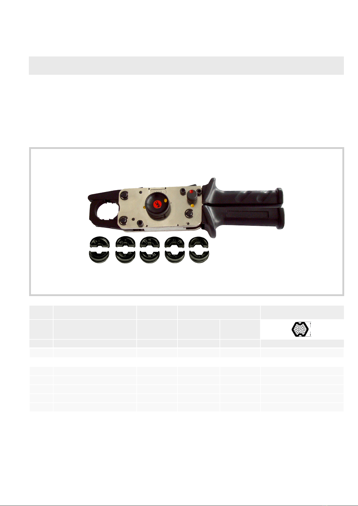
1 M-PZ13 1) 18�3700 -
Casquillos de engarce para M-PZ13 / Crimping dies to M-PZ13
2 MES-PZ-TB5/6 18�3701 6 10 4,3
3 MES-PZ-TB8/10 18�3702 10 2) 8 6,2
4 MES-PZ-TB9/16 18�3703 16 2) 6 7,1
5 MES-PZ-TB11/25 18�3704 25 2) 4 8,3
6 MES-PZ-TB13/35 18�3705 35 2 10,0
1) Alicates de engarce sin casquillos� Se ruega pedir por separado / Crimping pliers without crimping dies� Please order separately
2) No utilizar haces de cables! / Do not use bundled leads!
2 / 8
Instrucciones de seguridad Safety instructions
Solo personal adecuadamente cualificado y especialistas forma-
dos podrán realizar el montaje y la instalación de los productos,
teniendo en cuenta todas las regulaciones y normas de seguri-
dad legales aplicables.
Stäubli Electrical Connectors (Stäubli) no se responsabiliza del
incumplimiento de estas advertencias.
The products may be assembled and installed by electrically
skilled or instructed persons duly observing all applicable safety
regulations.
Stäubli Electrical Connectors (Stäubli) does not accept any liabil-
ity in the event of failure to observe these warnings.
Utilice solo los componentes y las herramientas indicados por
Stäubli. No se desvíe de los procedimientos de preparación y
montaje aquí descritos. En caso de una manipulación inadecua-
da, no se podrá garantizar la seguridad ni la conformidad con los
datos técnicos. No modifique el producto en ningún caso.
Use only the components and tools specified by Stäubli. In case
of self-assembly, do not deviate from the preparation and assem-
bly instructions as stated herein, otherwise Stäubli cannot give
any guarantee as to safety or conformity with the technical data.
Do not modify the product in any way.
Los conectores no fabricados por Stäubli que se pueden conec-
tar con elementos Stäubli, a veces denominados por los fabri-
cantes como “compatibles con Stäubli”, no cumplen con los req-
uisitos para una conexión eléctrica segura y estable a largo plazo,
por lo que, por motivos de seguridad, no pueden conectarse con
elementos Stäubli. Por tanto, Stäubli no se responsabilizará de
los daños causados por la conexión de conectores no autoriza-
dos por Stäubli con elementos Stäubli.
Connectors not originally manufactured by Stäubli which can be
mated with Stäubli elements and in some cases are even de-
scribed as ”Stäubli-compatible” by certain manufacturers do not
conform to the requirements for safe electrical connection with
long-term stability, and for safety reasons must not be plugged
together with Stäubli elements. Stäubli therefore does not ac-
cept any liability for any damages resulting from mating such
connectors (i.e. lacking Stäubli approval) with Stäubli elements.
Caution, risk of electric shock
(IEC 60417-6042)
Trabajos sin tensión
Deben respetarse las cinco reglas de oro de seguridad mientras
se trabaja en instalaciones eléctricas.
Después de haber sido identificadas las correspondientes insta-
laciones eléctricas, se deben aplicar los siguientes cinco requis-
itos esenciales siguientes en el orden especificado, a menos que
existan razones esenciales para hacerlo de otra forme:
- desconectar completamente;
- asegurar contra la posible reconexión;
- verificar la ausencia de tensión de trabajo;
- poner a tierra y en cortocircuito;
- protegerse frente a pares en tensión próximas.
Todo trabajador que participe en estos trabajos debe estar cuali-
ficado o autorizado o debe estar vigilado por un trabajador cual-
ificado o autorizado.
Fuente: EN 50110-1:2013 (DIN EN 50110-1, VDE 0105-1)
Work in a de-energized state.
Follow the five safety rules, when working on electrical
installations.
After the respective electrical installations have been identified, the
followingfiveessentialrequirementsshallbeundertakeninthespec-
ified order unless there are essential reasons for doing otherwise:
- disconnect completely;
- secure against re-connection;
- verify absence of operating voltage;
- carry out earthing and short-circuiting;
- provide protection against adjacent live parts.
Any person engaged in this work activity shall be electrically
skilled or instructed, or shall be supervised by such a person.
Source: EN 50110-1:2013
La protección contra descarga eléctrica debe comprobarse tam-
bién en las aplicaciones finales.
Protection against electric shock shall be checked in the end-use
applications too.
Do not disconnect under load
(IEC 60417-6070)
Permitida la conexión y desconexión bajo carga. Plugging and unplugging when live is permitted.
Caution
(ISO 7000-0434B)
Antes de cada uso debe comprobarse (particularmente el aislan-
te) de que no haya posibles defectos externos. En caso de duda
sobre la seguridad, se debe consultar a un especialista o el
conector debe ser reemplazado.
Each time the connector is used, it should previously be inspect-
ed for external defects (particularly the insulation). If there are any
doubts as to its safety, a specialist must be consulted or the
connector must be replaced.
3 / 8
2
AE
D
C
B
1
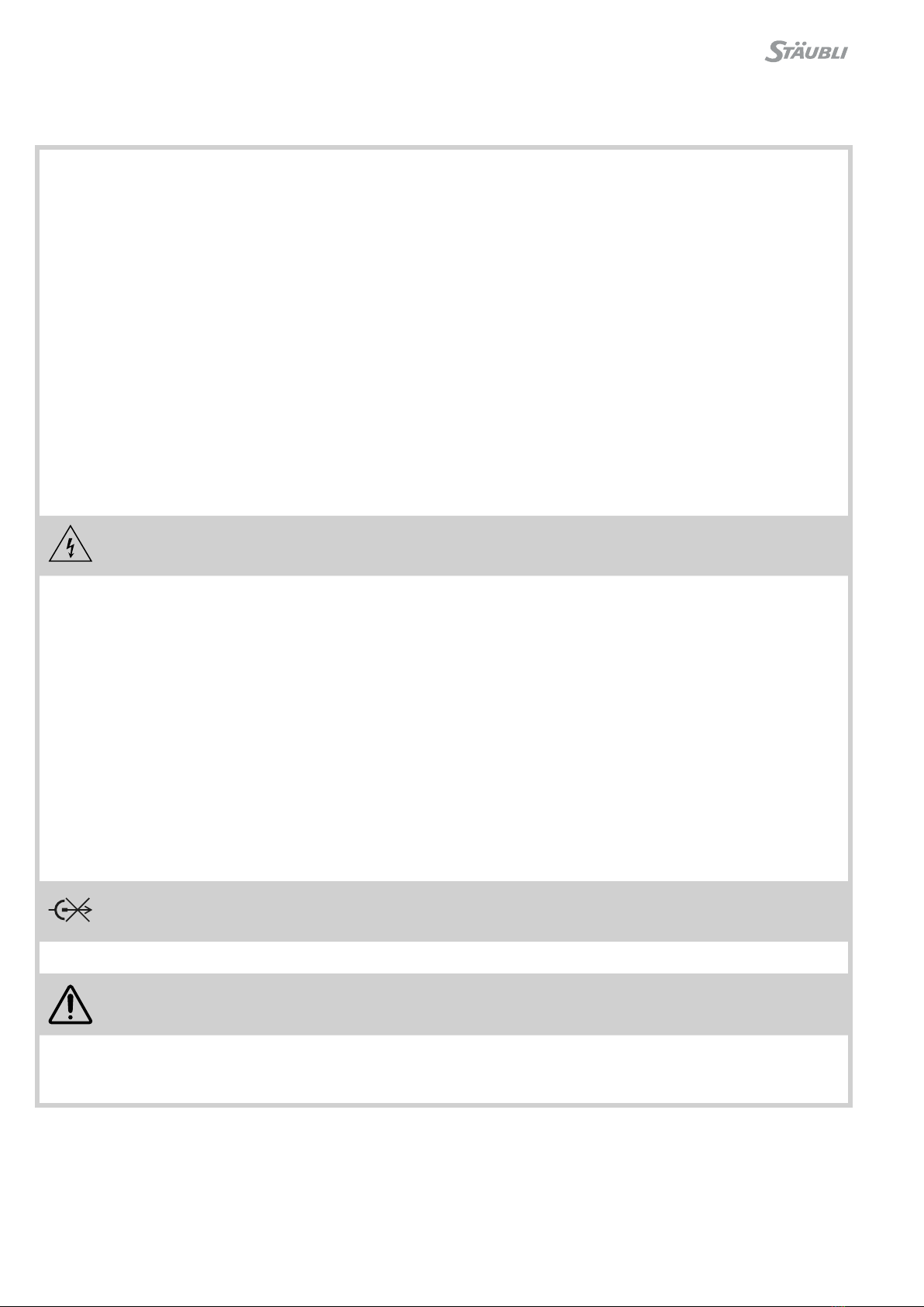
D
(ill. 1)
Liberar la palanca móvil Bgirando el
perno de bloqueo Ahasta alcanzar el
punto amarillo�
(ill. 1)
Release the movable handle Bby
turning the locking knob Ato the yel-
low point �
Nota:
durante esta operación, no
accionar la palanca manual�
Note:
Do not press together the handles�
(ill. 2)
Efectuar la aperturn total de la prensa
accionando el mecanismo de avance
rápido D�
(ill. 2)
Turn the quick feed knob Dto move
press to bottom limit of movement�
La herramienta de engarce es una prensa mecánica manual
con casquillos adaptables e intercambiables para engarzar:
•terminales de cables Cu y de conectores
•terminales tubulares de cables Cu y de conectores
•Casquillos de engarce Cu en conectores enchufables
The crimping tool is a mechanical hand press with interchan-
geable die inserts for crimping
•Copper cable lugs and connectors
•Tubular copper cable and connectors
•Crimp sleeves of connectors
Punto amarillo
Yellow point
Palanca de cierre abatible
Latch
Perno de bloqueo
Locking knob Trinquete de retención
Holding catch
Mecanismo de avance rápido
Quick feed knob
Palanca manual móvil
Movable handle
4 / 8
6
3
4
5
7
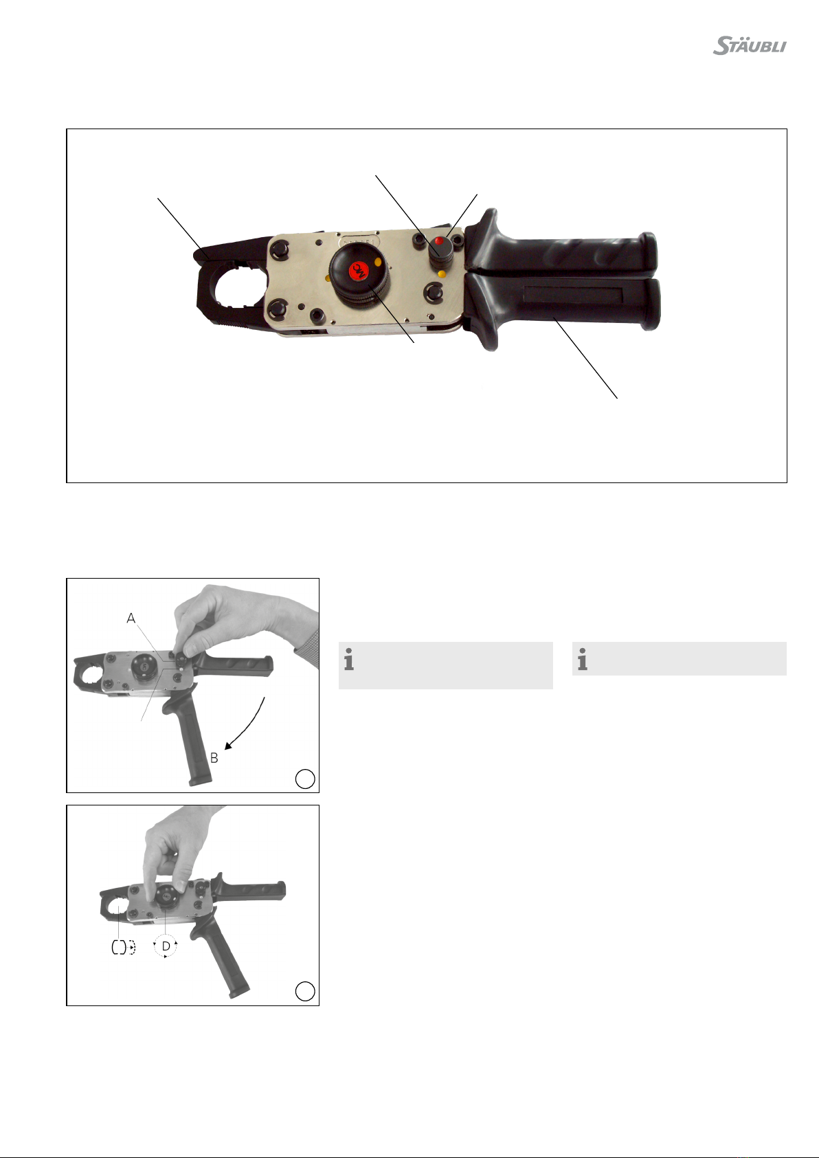
(ill. 3)
Abrir la palanca de cierre abatible C�
(ill. 3)
Open the latch C�
(ill. 4)
Alojar el casquillo de engarce adecua-
do a cada caso (consultar las instruc-
ciones de engarce que se indican en
el manual de montaje)�
(ill. 4)
Insert the appropriate crimping dies�
(Also see references to crimping in the
assembly instructions)�
(ill. 5)
Cerrar la palanca abatible C, colocar
el terminal del cable o del conector
enchufable�
(ill. 5)
Close latch C, insert cable connector,
cable lug or plug connector�
(ill. 6)
Observar la zona de engaste Z�
(ill. 6)
Observe the crimping zone Z�
(ill. 7)
Accionando el mecanismo de avance
rápido D, levantar el punzón del cas-
quillo y jar el conector.
(ill. 7)
Raise the die insert with the quick
feed knob D and x the connector in
place�
Casquillos de engarce
Inserts

5 / 8
9
10
8
11
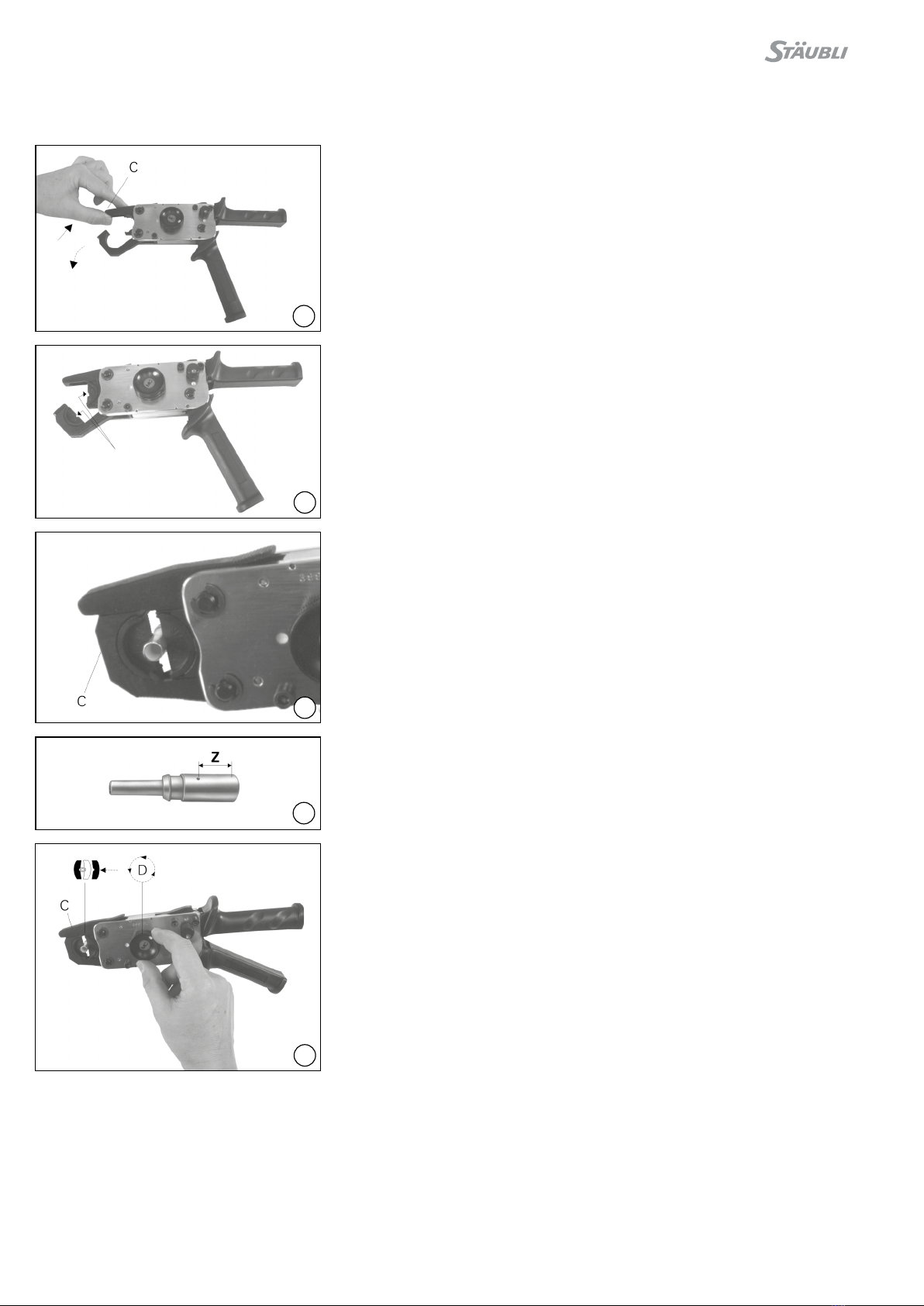
(ill. 8)
Colocar el cable 1) y proceder al engar-
ce accionando la palanca manual� Dos
o tres carreras después de haberse
alcanzado el punto muerto superior se
puede echar hacia atrás la pieza guía
con ayuda del mecanismo de avance
rápido Dy así poder retirar más rápi-
damente la pieza engarzada tal como
se describe en la Fig� 2�
(ill. 8)
Insert cable1) and effect crimping by
actuating the movable handle Bafter
reaching the upper limit of movement,
by means of the quick feed knob D
the guide can be returned to its start-
ing position as described under iIl� 2
to facilitate removal of the crimped
part�
1) Consultar las instrucciones de engarce que se
indican en el manual de montaje�
1) Also see references to crimping in the
assembly instructions�
(ill. 9)
Si se desea interrumpir el proceso de
engarce antes de haber alcanzado el
tope nal (con motivo de un posicio-
namiento erróneo o por equivocarse
de casquillo, por ejemplo), se deberá
proceder del modo siguiente: abatir
totalmente hacia fuera la palanca ma-
nual By sujetarla� Apretar el trinquete
de retención E(soltarlo eventualmente
dando un ligero golpe con un martillo
de plástico)�La palanca de cierre aba-
tible saltará y se abrirá y entonces se
puede echar hacia atrás el mecanismo
de avance rápido D�
(ill. 9)
Should the crimping operation have
to be stopped before completion
(wrong position, incorrect crimping
dies etc�) proceed as following: Fully
open handle B and hold tight� Press
down catch E(if necessary, release by
tapping gently with a plastic hammer)�
The latch springs open� The quick feed
knob Dcan now be turned back�
Nota:
Si el proceso de engarce está
casi terminado, éste ya no se puede
interrumpir y en ese caso, hay que
terminar el proceso antes de poder
abrir los alicates de engarce�
Note:
When the crimping action is
almost nished it cannot be stopped.
The crimp must then be completed
before the tool can be opened�
Comprobación del funcionamiento
de los alicates de engarce Function test of the crimping
pliers
Para cada uso en concreto, deberá
comprobarse que la presión de los
alicates y la profundidad del prensado
correspondiente estén de acuerdo
con la información que proporciona el
fabricante�
The crimping depth of crimping pliers,
adjusted by the manufacturer should
be tested from time to time�
Material de prueba Test equipment
(ill. 10)
Casquillo de prueba, MPS-PZ13
Código 18�3707
Varilla redonda de prueba,
MALU-PZ13,
Código 18�3708
(ill. 10)
Test insert, MPS-PZ13
Order No� 18�3707
Round test rod,
MALU-PZ13
Order No� 18�3708
(ill. 11)
Con los casquillos de prueba se com-
prime rmemente la varilla redondo
de prueba (AL99,5) diámetro 16mm.
La dimensión de 14,15mm. no debe
en ningún caso superar los 14�25� En
el caso de una desviación importante,
enviar los alicates de engarce al fabri-
cante para un nuevo reajuste�
(ill. 11)
Press the round test rod (AL99,5)
Ø 16mm with the test inserts. The
size 14,15mm should not exceed
14,25mm. With other test results, the
crimping pliers should be adjusted by
the manufacturer�
Nota:
Las reparaciones deben ser
solamente realizadas por personal
técnico especializado�
Note:
Repairs must only be performed
by qualied personnel.

6 / 8
Notas / Notes:

7 / 8
Notas / Notes:

8 / 8
Fabricante/Producer:
Stäubli Electrical Connectors AG
Stockbrunnenrain 8
4123 All schwil/Switzerland
Tel. +41 61 306 55 55
Fax +41 61 306 55 56
www.staubli.com/electrical
© by Stäubli Electrical Connectors AG, Switzerland – MA224 – 07.2019, Index c, Marketing Communications – Sujeto a modicaciones / Subject to alterations
Notas / Notes:
Table of contents
Other Staubli Power Tools manuals

Staubli
Staubli PV-AZM User manual

Staubli
Staubli CTD-M-CZ User manual

Staubli
Staubli MA251 User manual

Staubli
Staubli M-PZ-T2600 User manual

Staubli
Staubli MA251 User manual

Staubli
Staubli MA251 User manual

Staubli
Staubli M-PZ13 User manual

Staubli
Staubli M-PZ-T2600 User manual

Staubli
Staubli PV-MS-PLS User manual

Staubli
Staubli PV-MS-PLS User manual

Staubli
Staubli PV-CZM-BS User manual

Staubli
Staubli M-PZ-T2600 User manual

Staubli
Staubli MA251 User manual

Staubli
Staubli PV-MS-PLS User manual

Staubli
Staubli M-PZ13 User manual

Staubli
Staubli MA251 User manual

Staubli
Staubli MA251 User manual

Staubli
Staubli MA251 User manual

Staubli
Staubli MA224 User manual


