Staubli MA251 User manual

1 / 12
PV-CZM...
* UL le E343181
MA251 (fr_en)
Notice d‘utilisation
MA251 (fr_en)
Operating instructions
Pince à sertir PV-CZM...
pour MC3, MC4 et MC4-EVO 2
Crimping pliers PV-CZM...
for MC3, MC4 and MC4-EVO 2
Sommaire
Consignes de sécurité ����������������������������������������������������������������2
Version pour MC3......................................................................3
Version pour MC4......................................................................4
Version pour MC4-EVO 2 ..........................................................5
Changement de la matrice de sertissage ..................................7
— Démontage de la matrice de sertissage................................. 7
— Montage de la matrice de sertissage .....................................7
Sertissage ..................................................................................8
Qualité du sertissage .................................................................9
Notes ..................................................................................10-12
Content
Safety Instructions����������������������������������������������������������������������2
Explanation for MC3..................................................................3
Explanation for MC4..................................................................4
Explanation for MC4-EVO 2 ......................................................5
Exchanging the crimping insert.................................................7
— Removing the crimping insert................................................7
— Fitting the crimping insert......................................................7
Crimping....................................................................................8
Crimping quality ........................................................................9
Notes ..................................................................................10-12

2 / 12
Consignes de sécurité Safety Instructions
Le montage et l’installation des produits ne doivent être ef-
fectués que par du personnel qualié et formé en respectant
toutes les dispositions de sécurité et réglementations légales
applicables.
Stäubli Electrical Connectors (Stäubli) décline toute responsa-
bilité en cas de non-respect de ces consignes.
The products may be assembled and installed exclusively by
suitably qualied and trained specialists duly observing all ap-
plicable safety regulations.
Stäubli Electrical Connectors (Stäubli) does not accept any li-
ability in the event of failure to observe these warnings.
Utiliser uniquement les pièces et outils recommandés par
Stäubli. Suivre scrupuleusement les étapes de préparation et
de montage décrites ici, faute de quoi ni la sécurité ni le res-
pect des caractéristiques techniques ne sont garantis. Ne pas
modier le produit d’une quelconque manière.
Use only the components and tools specied by Stäubli. In
case of self-assembly, do not deviate from the preparation
and assembly instructions as stated herein, otherwise Stäubli
cannot give any guarantee as to safety or conformity with the
technical data. Do not modify the product in any way.
Les travaux décrits ici ne doivent pas être effectués
sur des parties parcourues par un courant ou sous
tension.
The work described here must not be carried out
on live or load-carrying parts.
La protection contre les chocs électriques doit être
assurée par le produit nal et garantie par l’utili-
sateur.
Protection from electric shock must be assured by
the end product (i.e. by the correctly assembled
plug connector) and by its user.
Stäubli déconseille d’utiliser des câbles PVC ou des
câbles non étamés du type H07RN-F.
For safety reasons, Stäubli does strongly recom-
mend not to use PVC cables or untinned cables of
type H07RN-F.
Pour des caractéristiques techniques détaillées, se
reporter au catalogue des produits.
For further technical data please see the product
catalogue.
Explication des symboles Explanation of the symbols
Mise en garde contre une tension électrique dan-
gereuse Warning of dangerous voltages
Mise en garde contre un danger Warning of a hazard area
Remarque ou conseil utile Useful hint or tip
3 / 12
1
2
3
45
4
Pos. Section du câble
Cable cross section
approprié pour
suitable for
mm2AWG
4410 PV-SP3/4
PV-BP3/4
510 PV-SP4/10
PV-BP4/10
Pos. Section du câble
Cable cross section
approprié pour
suitable for
mm2AWG
12,5 14 PV-SP3/4
PV-BP3/4
2412 PV-SP3/4
PV-BP3/4
36PV-SP3/6
PV-BP3/6
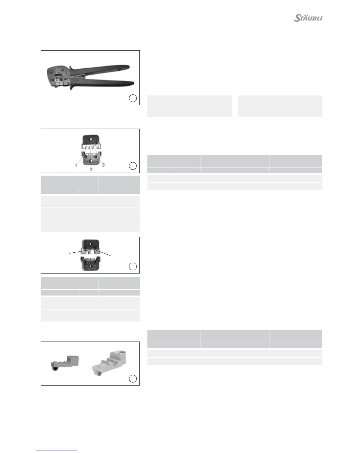
Version pour MC3 Explanation for MC3
(ill. 1)
Pince à sertir PV-CZM-16100A
incluant deux positionneurs interchan-
geables et deux matrices de sertis-
sage interchangeables.
(ill. 1)
Crimping pliers PV-CZM-16100A
incl. two interchangeable Locators
and two interchangeable crimping
inserts
Plage de sertissage: 2,5 / 4 / 6mm2
(14 / 12 / 10AWG)
No. de Cde.: 32.6020-16100A
Crimping range: 2,5 / 4 / 6mm2
(14 / 12 / 10AWG)
Order No.: 32.6020-16100A
Pièces détachées Individual parts
(ill. 2 + 3)
Matrices de sertissage interchangea-
bles.
(ill. 2 + 3)
Interchangeable crimping inserts
Plage de sertissage
Crimping range Type No. de Cde.
Order No.
mm2AWG
2,5 / 4 / 6 14 / 12 / 10 PV-ES-CZM-16100 32.6021-16100
4 / 10 PV-ES-CZM-17100 32.6021-17100
(ill. 4)
Positionneurs interchangeables
(ill. 4)
Interchangeable locators
Plage de sertissage
Crimping range Type No. de Cde.
Order No.
mm2AWG
2,5 / 4 / 6 12 / 10 PV-LOC-A 32.6039
4 / 10 PV-LOC-A10 32.6049
Ces types de positionneurs sont appro-
priés uniquement pour Ø 3mm.
This locator types are for Ø 3mm only
4 / 12
5
12
3
5
4
6
8
7
6
7
8
Version pour MC4 Explanation for MC4
(ill. 5)
Pince à sertir incluant un positionneur
PV-LOC et une matrice de sertissage
intégrée.
(ill. 5)
Crimping pliers incl. locator PV-LOC
and built-in crimping insert
Plage de sertissage: 1,5 / 2,5 / 4mm2
(14 / 12AWG)
Type: PV-CZM-18100
No. de Cde.: 32.6020-18100
Crimping range: 1,5 / 2,5 / 4mm2
(14 / 12AWG)
Type: PV-CZM-18100
Order No.: 32.6020-18100
Plage de sertissage: 2,5 / 4 / 6mm2
(12 / 10AWG)
Type: PV-CZM-19100
No. de Cde.: 32.6020-19100
Crimping range: 2,5 / 4 / 6mm2
(12 / 10AWG)
Type: PV-CZM-19100
Order No.: 32.6020-19100
Plage de sertissage: 4 / 10mm2
Type: PV-CZM-20100
No. de Cde.: 32.6020-20100
Crimping range: 4 / 10mm2
Type: PV-CZM-20100
Order No.: 32.6020-20100
Plage de sertissage: 6 / 10mm2
Type: PV-CZM-21100
No. de Cde.: 32.6020-21100
Crimping range: 6 / 10mm2
Type: PV-CZM-21100
Order No.: 32.6020-21100
Plage de sertissage: 8 / 12 / 10AWG
Type: PV-CZM-22100
No. de Cde.: 32.6020-22100
Crimping range: 8 / 12 / 10AWG
Type: PV-CZM-22100
Order No.: 32.6020-22100
Pièces détachées Individual parts
(ill. 6 + 7 + 8 + 9 + 10)
Matrices de sertissage interchan-
geables.
(ill. 6 + 7 + 8 + 9 + 10)
Interchangeable crimping inserts
Plage de sertissage
Crimping range
Ty p
Type
No. de Cde.
Order No.
mm2AWG
1,5 / 2,5 / 4 14 / 12 PV-ES-CZM-18100 32.6021-18100
Plage de sertissage
Crimping range
Ty p
Type
No. de Cde.
Order No.
mm2AWG
2,5 / 4 / 6 12 / 10 PV-ES-CZM-19100 32.6021-19100
Plage de sertissage
Crimping range
Ty p
Type
No. de Cde.
Order No.
mm2AWG
4 / 10 PV-ES-CZM-20100 32.6021-20100
Pos. Section du câble
Cable cross section
approprié pour
suitable for
mm2AWG
11,5 14 PV-SP4/2.5
PV-BP4/2.5
22,5 PV-SP4/2.5
PV-BP4/2.5
3412 PV-SP4/6
PV-BP4/6
Pos. Section du câble
Cable cross section
approprié pour
suitable for
mm2AWG
42,5 PV-SP4/2.5
PV-BP4/2.5
5412 PV-SP4/6
PV-BP4/6
66 10 PV-SP4/6
PV-BP4/6
Pos. Section du câble
Cable cross section
approprié pour
suitable for
mm2
74PV-SP4/6
PV-BP4/6
810 PV-SP4/10
PV-BP4/10
5 / 12
9
10
9
11
11
12
13 10
12
Plage de sertissage
Crimping range Type No. de Cde.
Order No.
mm2
6 / 10 PV-ES-CZM-21100 32.6021-21100
Plage de sertissage
Crimping range Type No. de Cde.
Order No.
AWG
8 / 12 /10 PV-CZM-22100 32.6020-22100
(ill. 11)
Positionneur PV-LOC
No. de Cde.: 32.6040
Positionneur PV-LOC-B
No. de Cde.: 32.6055
Remarque:
Pour la pince à sertir
PV-CZM-22100 utilisez le position-
neur PV-LOC-B�
(ill. 11)
Locator PV-LOC
Order No.: 32.6040
Locator PV-LOC-B
Order No.: 32.6055
Note:
When using the crimping tool
PV-CZM-22100, please use the
locator PV-LOC-B�
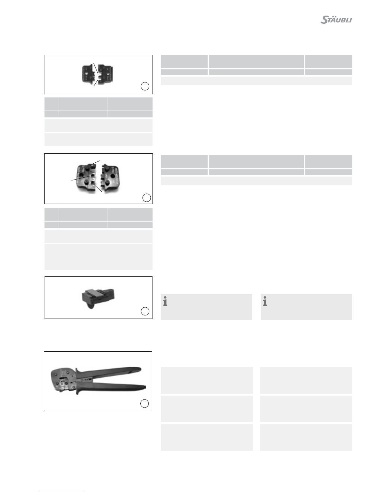
Version pour MC4-EVO 2 Explanation for MC4-EVO 2
(ill. 12)
Pince à sertir incluant un positionneur
et une matrice de sertissage intégrée
(ill. 12)
Crimping pliers incl. Locator and built
in crimping insert
Plage de sertissage: 1,5 / 2,5 / 4mm2
(14 / 12AWG)
Type: PV-CZM-40100
No. de Cde.: 32.6020-40100
Crimping range: 1,5 / 2,5 / 4mm2
(14 / 12AWG)
Type: PV-CZM-40100
Order No.: 32.6020-40100
Plage de sertissage: 2,5 / 4 / 6mm2
(14 / 12 / 10AWG)
Type: PV-CZM-41100
No. de Cde.: 32.6020-41100
Crimping range: 2,5 / 4 / 6mm2
(14 / 12 / 10AWG)
Type: PV-CZM-41100
Order No.: 32.6020-41100
Plage de sertissage: 4 / 10mm2
(12 / 8AWG)
Type: PV-CZM-42100
No. de Cde.: 32.6020-42100
Crimping range: 4 / 10mm2
(12 / 8AWG)
Type: PV-CZM-42100
Order No.: 32.6020-42100
Pos. Section du câble
Cable cross section
approprié pour
suitable for
mm2
96PV-SP4/6
PV-BP4/6
10 10 PV-SP4/10
PV-BP4/10
Pos. Section du câble
Cable cross section
approprié pour
suitable for
AWG
11 8PV-SP4/8
PV-BP4/8
12 10 PV-SP4/6
PV-BP4/6
13 12 PV-SP4/6
PV-BP4/6

6 / 12
13
14
15
16
2
1
3
5
4
6
7
8
Pièces détachées Individual parts
(ill. 13 + 14 + 15)
Matrices de sertissage interchan-
geables
(ill. 13 + 14 + 15)
Interchangeable crimping inserts
Plage de sertissage
Crimping range Type No. de Cde.
Order No.
mm2AWG
1,5 / 2,5 / 4 14 / 12 PV-ES-CZM-40100 32.6021-40100
Plage de sertissage
Crimping range Type No. de Cde.
Order No.
mm2AWG
2,5 / 4 / 6 14 / 12 / 10 PV-ES-CZM-41100 32.6021-41100
Plage de sertissage
Crimping range Type No. de Cde.
Order No.
mm2AWG
4 / 10 12 / 8 PV-ES-CZM-42100 32.6021-42100
(ill. 16)
Positionneur PV-LOC-C
No. de Cde.: 32.6056
(ill. 16)
Locator PV-LOC-C
Order no.: 32.6056
Pos. Section du câble
Cable cross section
approprié pour
suitable for
mm2AWG
11,5 PV-SP4-EVO 2/2,5
PV-BP4-EVO 2/2,5
22,5 14 PV-SP4-EVO 2/2,5
PV-BP4-EVO 2/2,5
3412 PV-SP4-EVO 2/6
PV-BP4-EVO 2/6
Pos. Section du câble
Cable cross section
approprié pour
suitable for
mm2AWG
42,5 14 PV-SP4-EVO 2/2,5
PV-BP4-EVO 2/2,5
5412 PV-SP4-EVO 2/6
PV-BP4-EVO 2/6
66 10 PV-SP4-EVO 2/6
PV-BP4-EVO 2/6
Pos. Section du câble
Cable cross section
approprié pour
suitable for
mm2AWG
7412 PV-SP4-EVO 2/6
PV-BP4-EVO 2/6
810 8PV-SP4-EVO 2/10
PV-BP4-EVO 2/10
2
1
3
6
5
4
7
8

7 / 12
21
22
19
20
17
18
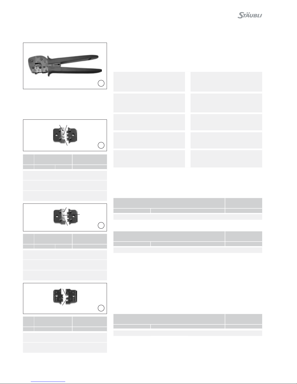
Changement de la matrice de
sertissage
Exchanging the crimping
inserts
Démontage de la matrice de ser-
tissage
Removing the crimping insert
(ill. 17)
Fermer la pince à sertir
(ill. 17)
Close the crimping tool
(ill. 18)
Dévisser la vis longue S et la vis
courte S1 puis ouvrir la pince à sertir
(serrer à fond puis relâcher).
(ill. 18)
Unscrew both the long S and the
short S1 screw. Open the crimping
tool (press completely together and
release).
(ill. 19)
Extraire la matrice de sertissage supé-
rieure.
(ill. 19)
Remove the upper crimping insert.
(ill. 20)
Extraire la matrice de sertissage infé-
rieure.
(ill. 20)
Remove the lower crimping insert.
Montage de la matrice de sertis-
sage
Fitting the crimping insert
(ill. 21)
Ouvrir la pince à sertir (serrer à fond
puis relâcher). Introduire les deux ma-
trices de sertissage. Le marquage doit
être du même côté que le marquage
de la pince à sertir.
Fermer la pince à sertir. Visser les
deux matrices de sertissage.
(ill.21)
Open the crimping tool (press com-
pletely together and release). Insert
both crimping inserts. The markings
must be on the same side as the
marking on the crimping tool.
Close crimping tool and screw both
crimping inserts tight.
(ill. 22)
Insérer le positionneur dans la goupille
de guidage.
(ill. 22)
Insert locator into the guide pin.

8 / 12
25
26
23
24
(ill. 23)
Faire pivoter le positionneur (retenu
magnétiquement).
(ill. 23)
Rotate the locator (held magnetically)
(ill. 24)
Bloquer le positionneur.
(ill. 24)
Lock the locator.
Sertissage Crimping
Exemple pour ADBP3/... et
ADSP3/...
Example for ADBP3/... and
ADSP3/...
(ill. 25)
Enlever le positionneur. Introduire
le câble dénudé par le côté gauche
jusqu‘à ce que l‘isolant bute sur la
matrice de sertissage. Fermer com-
plètement la pince à sertir. Contrôler
visuellement le sertissage.
(ill. 25)
Remove the locator. Insert the
stripped cable on the left side until the
insulation comes into contact with the
crimping insert. Close crimping tool
completely.
Check crimp.
Exemple pour KBT4.../KST4... Example for KBT4.../KST4...
(ill. 26)
Ouvrir l‘étrier K et le maintenir. Insérer
le contact dans la zone de section
appropriée de la pince à sertir. Tourner
les languettes de sertissage vers le
haut. Relacher l‘étrier K. Le contact
est xé.
(ill. 26)
Open and hold clamping clip K. Insert
contact in the appropriate cross-sec-
tion range of the crimping tool. Turn
contact till crimping tabs face the top.
Release clamping clip K. The contact
is secured.

9 / 12
29
27
28
(ill. 27)
Serrer légèrement la pince pour que
les pattes de sertissage se trouvent
à coup sûr dans la matrice de sertis-
sage.
(ill. 27)
Lightly press the pliers together so
that the crimping tabs lie securely
within the crimping die.
(ill. 28)
Introduire le câble dénudé jusqu‘à ce
que l‘isolant bute sur la matrice de
sertissage. Fermer complètement la
pince à sertir.
(ill. 28)
Insert the stripped cable until the
insulation comes into contact with the
crimping insert. Close crimping tool
completely.
Qualité du sertissage Crimping quality
La hauteur de sertissage permet
d’évaluer la qualité du sertissage.
Vous trouverez les valeurs typiques
pour les câbles FLEX-SOL-XL et
Studer BETAam® dans le tableau
suivant.
The quality of the crimp can be as-
sessed on the basis of the crimp
height. Typical values for the cables
FLEX-SOL-XL and Studer BETAam®
are shown in the following table.
(ill. 29)
Contrôler le sertissage visuellement.
(ill. 29)
Visually check the crimp.
MC4 / MC4-EVO 2 MC3
ACable
Hauteur de
seritage
Crimp height
mm2mm
1,5 FLEX-SOL-XL
BETAam®
1,65
1,65
2,5 FLEX-SOL-XL
BETAam®
1,80
1,80
4FLEX-SOL-XL
BETAam®
2,15
2,15
6FLEX-SOL-XL
BETAam®
2,40
2,40
10 FLEX-SOL-XL 3,02
ACable
Hauteur de
seritage
Crimp height
mm2mm
1,5 FLEX-SOL-XL
BETAam®
2,20
2,20
2,5 FLEX-SOL-XL
BETAam®
2,20
2,20
4FLEX-SOL-XL
BETAam®
2,50
2,50
6FLEX-SOL-XL
BETAam®
3,12
3,12
10 FLEX-SOL-XL 4,80

10 / 12
Notes:

11 / 12
Notes:

12 / 12
Fabricant/Producer:
Stäubli Electrical Connectors AG
Stockbrunnenrain 8
4123 Allschwil/Switzerland
Tél. +41 61 306 55 55
Fax +41 61 306 55 56
www.staubli.com/electrical
© by Stäubli Electrical Connectors AG, Switzerland – MA251 – 01.2017, Index a, Marketing Communications – Sous réserve de modications / Subject to alterations
Notes:
Other manuals for MA251
7
Table of contents
Other Staubli Power Tools manuals

Staubli
Staubli MA251 User manual

Staubli
Staubli M-PZ13 User manual

Staubli
Staubli M-PZ-T2600 User manual

Staubli
Staubli MA251 User manual

Staubli
Staubli PV-MS-PLS User manual

Staubli
Staubli PV-MS-PLS User manual

Staubli
Staubli MA251 User manual

Staubli
Staubli PV-MS-PLS User manual

Staubli
Staubli M-PZ-T2600 User manual

Staubli
Staubli PV-CZM-BS User manual


Popular Power Tools manuals by other brands


Bosch
Bosch GNA 3,5 Professional Original instructions

Promac
Promac 378VTE manual

MSW Motor Technics
MSW Motor Technics MSW-ETT-O-113 user manual

Stahls
Stahls STXBP-120 Operator's manual

Atlas Copco
Atlas Copco ETD ST81-120-13-T75 Original product instructions

Ribimex
Ribimex RIBITECH PRBAT20/SS65SB User and maintenance manual