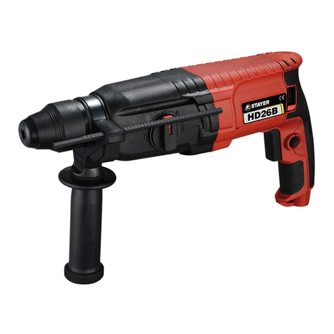
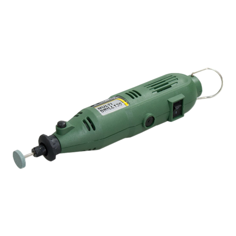
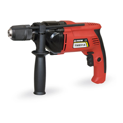
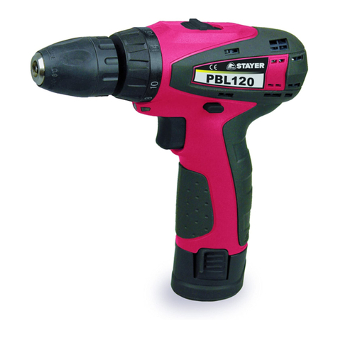
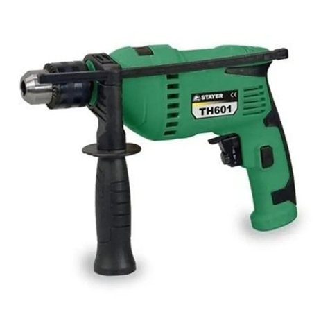
stayer TH610 User manual

www.grupostayer.com
Manual de instrucciones
ES
Área Empresarial Andalucía - Sector I
Calle Sierra de Cazorla nº7
C.P: 28320 Pinto (Madrid) SPAIN
Email: sales@grupostayer.com
Email: info@grupostayer.com
Istruzioni d’uso
IT
Operating instructions
GB
Bedienungsanleitung
DE
Instructions d’emploi
FR
Manual de instruções
P
Kullanma Kılavuzu
TR
TH610
TH610A
TH710A
TH710AK
TH1000AK
Instrukcja obsługi
PL

1
2
2
13
6
5
1
3
7
7
4
8
7

6 7
6
1
8
3
A
B
5
8
4 5
1a
2
9
9

6.1.
TH610
TH610A
TH710A
TH710AK
TH1000AK
W
600
710
1000
-1
min
0-3000
0-3000
0-3000
-1
min
0-41600
0-48000
0-44800
mm.
13
13
13
Ø max
13
13
13
Ø max
16
13
20
Ø max
25
25
25
kg
2
2
2.3
L dB(A)
pA
97,5
89
97,5
L dB(A)
WA
105
95
105
2
a m/s
h
3
3
3
rpm
ipm
K=3 dB
2
K=1.5 m/s
kg

Este manual es acorde con la fecha de fabricación de su
máquina, información que encontrará en la tabla de datos
técnicos de la maquina adquirida, buscar actualizaciones
de manuales de nuestras maquinas en la página web:
www.grupostayer.com
El taladro ha sido concebido para hacer agujeros en
madera, hierro, metales no férreos y roca utilizando la
broca indicada.
1. Índice
página
2.Instrucciones especificas de seguridad....................1
3.Instrucciones de puesta en servicio...........................1
3.1 Colocación de la herramienta........................................1
3.2 Montaje...........................................................................2
3.3 Conexión eléctrica..................................................2
3.4 Descripción ilustrada..............................................2
4.Instrucciones de funcionamiento..............................2
4.1 Colocación y pruebas.............................................2
4.2 Cambio de herramienta..........................................3
5.Instrucciones de mantenimiento y servicio...............3
5.1 Limpieza.................................................................3
5.2 Servicio de reparación............................................3
5.3 Garantía.................................................................4
5.4 Eliminación.............................................................4
6.Marcado Normativo.....................................................4
6.1 Características Técnicas........................................4
6.2 Declaración de Conformidad CE.............................4
2. Instrucciones Especificas de Seguridad
Utilice unos protectores auditivos. El ruido intenso
puede provocar sordera.
Utilizar la herramienta eléctrica con las empuñaduras
adicionales que se adjuntan con el aparato. Vd. puede
accidentarse si pierde el control sobre el aparato.
Utilice unos aparatos de exploración adecuados para
detectar posibles tuberías de agua y gas o cables
eléctricos ocultos, o consulte a la compañía local que
le abastece con energía. El contacto con cables eléctricos
puede electrocutarle o causar un incendio. Al dañarlas
tuberías de gas, ello puede dar lugar a una explosión. La
perforación de una tubería de agua puede redundar en
daños materiales o provocar una electrocución.
Únicamente sujete el aparato por las empuñaduras
aisladas al realizar trabajos en los que el útil pueda
tocar conductores eléctricos ocultos o el propio cable
del aparato. El contacto con conductores portadores de
tensión puede hacer que las partes metálicas del aparato le
provoquen una descarga eléctrica.
Trabajar sobre una base firme sujetando la
herramienta eléctrica con ambas manos. La
herramienta eléctrica es guiada de forma más segura con
ambas manos.
Asegure la pieza de trabajo. Una pieza de trabajo fijada
con unos dispositivos de sujeción, o en un tornillo de banco,
se mantiene sujeta de forma mucho más segura que con la
mano.
No trabaje materiales que contengan amianto.
El amianto es cancerígeno.
Tome unas medidas de protección adecuadas si al
trabajar pudiera generarse polvo combustible,
explosivo, o nocivo para la salud. Por ejemplo: ciertos
tipos de polvo son cancerígenos. Colóquese una
mascarilla antipolvo y, si su aparato viene equipado con la
conexión correspondiente, utilice además un
equipo de aspiración adecuado.
Mantenga limpio su puesto de trabajo. La mezcla de
diversos materiales es especialmente peligrosa. Las
aleaciones ligeras en polvo pueden arder o explotar.
Antes de depositarla, esperar a que se haya detenido la
herramienta eléctrica. El útil puede engancharse y
hacerle perder el control sobre la herramienta eléctrica.
No utilice la herramienta eléctrica si el cable está
dañado. No toque un cable dañado, y desconecte el
enchufe de la red, si el cable se daña durante el trabajo.
Un cable dañado comporta un mayor riesgo de
electrocución.
“Aviso - Leer el manual de instrucciones para
reducir cualquier riesgo de sufrir daños”
Usar protección para los oídos.
La exposición al ruido puede ser perjudicial para el
oído.
Es preciso ponerse una mascarilla de
protección.
Puede generarse polvo dañino para la salud
cuando se realicen trabajos en madera o en otros
materiales. ¡Está prohibido trabajar con material que
contenga amianto!
Llevar gafas de protección.
Durante el trabajo, la expulsión de chispas, astillas,
virutas y polvo por el aparato pueden provocar
pérdida de vista.
3. Instrucciones de puesta en servicio
3.1 Colocación de la herramienta
Lea íntegramente estas advertencias de peligro
e instrucciones. En caso de no atenerse a las
advertencias de peligro e instrucciones siguientes,
ello puede ocasionar una descarga eléctrica, un
incendio y/o lesión grave.
Utilizar la máquina sólo en los casos que se indican
explícitamente como de uso adecuado. Cualquier otro uso
no será adecuado.
En caso de uso inadecuado, el fabricante no se hace
responsable de daños o lesiones de cualquier tipo; el
responsable es el usuario u operario de la máquina.
ESPAÑOL
1
1

Comprobar de forma periódica que la broca o la
herramienta esté bien sujeta (para ello, desenchufar el
aparato).
3.3 Conexión eléctrica
¡Observe la tensión de red! La tensión alimentación
deberá coincidir con las indicaciones en la placa de
características de la herramienta eléctrica. Las
herramientas eléctricas marcadas con 230 V pueden
funcionar también a 220 V.
Cuando el cable de conexión a la red de este aparato esté
dañado, deberá ser sustituido por el fabricante o su servicio
de asistencia técnica o por una persona cualificada para
ello, evitando así cualquier peligro.
3.4 Descripción Ilustrada
1. Portabrocas
2. Tope de profundidad de perforación
3. Conmutador taladro/taladro percutor
4. Botón de enclavamiento
5. Interruptor ON/OFF
6. Conmutador derecha/izquierda
7. Empuñadura adicional
8. Regulador de velocidad
9. Selector de velocidad mecánico
4. Instrucciones de funcionamiento
4.1 Colocación y pruebas
Interruptor ON/OFF (fig. 7/pos. 5)
En primer lugar, introducir una broca adecuada en el
aparato (véase 5.3).
Enchufar el aparato en una toma de corriente adecuada.
Aplicar el taladro directamente en el punto a taladrar.
Conexión:
Pulsar el interruptor ON/OFF 5
Modo en continuo:
Asegurar el interruptor ON/OFF 5 con el botón de
enclavamiento 4.
Desconexión:
Pulsar brevemente el interruptor ON/OFF 5.
Ajustar la velocidad (fig. 7/pos. 5)
La velocidad se puede controlar de forma continua durante
el funcionamiento.
Seleccionar la velocidad pulsando con mayor o menor
fuerza el interruptor ON/OFF 5.
Elección de la velocidad adecuada: la velocidad
adecuada depende de la pieza, del modo de
funcionamiento y de la broca que se utiliza.
Poca presión en el interruptor ON/OFF 5:
velocidad baja (adecuado para: tornillos pequeños,
materiales blandos)
Mayor presión en el interruptor ON/OFF 5:
velocidad alta (adecuado para: tornillos grandes/largos,
materiales duros)
ESPAÑOL
2
2
3.2 Montaje
Antes de conectar la máquina, asegurarse de que los datos
de la placa de identificación coincidan con los datos de la
red eléctrica.
Antes de cualquier manipulación en la
herramienta eléctrica, sacar el enchufe de red de
la toma de corriente.
Montar la empuñadura adicional (fig. 2-3/pos. 7)
La empuñadura adicional 7 sirve para facilitar la sujeción
del taladro de percusión. Por este motivo, no utilizar el
aparato sin la empuñadura adicional.
La empuñadura adicional 7 se sujeta al taladro de
percusión por apriete. La sujeción se aprieta girando
la empuñadura hacia la derecha, mientras que si se gira
hacia la izquierda se suelta.
Primero se debe montar la empuñadura adicional 7.
Para ello, girar la empuñadura para abrir bien sujeción de
forma que se pueda introducir la empuñadura adicional a
través del portabrocas 1.
Tras introducir la empuñadura adicional 7 girarla hasta
alcanzar la posición de trabajo más cómoda.
A continuación, girar la empuñadura en la dirección
contraria hasta que la empuñadura adicional quede bien
sujeta.
La empuñadura adicional 7 está indicada tanto para
diestros como para zurdos.
Montar y ajustar el tope de profundidad
(fig. 4/pos. 2)
La empuñadura adicional 7 se encarga de sujetar el tope de
profundidad 2. La sujeción se suelta o aprieta de nuevo
girando la empuñadura. Soltar la fijación y colocar el tope
de profundidad 2 en la abertura prevista en la empuñadura
adicional.
Colocar el tope de profundidad 2 al mismo nivel que la
broca.
Tirar hacia atrás del tope de profundidad para lograr la
profundidad de perforación deseada.
Girar de nuevo la empuñadura adicional 7 hasta que quede
bien sujeta.
Taladrar el agujero hasta que el tope de
profundidad 2 toque la pieza.
Colocar la broca (fig. 5-6)
Desenchufar el aparato antes de realizar ajustes.
El portabrocas de sujeción rápida 1 está dotado de un
cierre de bloqueo:
Bloquear = presionar el manguito (a) hacia delante
Desbloquear = presionar el manguito (a) hacia atrás
Soltar el tope de profundidad según se describe en el
apartado anterior y desplazarlo en dirección a la
empuñadura adicional. Así se puede acceder libremente al
portabrocas 1.
Este taladro de percusión está dotado de un portabrocas
de sujeción rápida 1. Desenroscar el portabrocas 1.
La perforación del taladro debe ser lo suficientemente
grande para alojar la broca.
Elegir la broca adecuada. Introducir la broca al máximo
posible en el orificio del portabrocas.
Desenroscar el portabrocas 1. Comprobar si la broca está
bien sujeta en el portabrocas 1.

Poner el conmutador 3 en la posición B (taladro percutor)
en cuanto la broca haya perforado la baldosa/azulejo.
4.2 Cambio de herramientas
Con el fin de evitar que se dañe el engranaje, el conmutador
taladro/taladro percutor sólo se deberá cambiar cuando la
herramienta se haya detenido por completo.
5. Instrucciones de mantenimiento y servicio
Antes de cualquier manipulación en la herramienta
eléctrica, sacar el enchufe de red de la toma de
corriente.
5.1 Limpieza
Reducir al máximo posible la suciedad y el polvo en los
dispositivos de seguridad, las rendijas de ventilación y la
carcasa del motor. Frotar el aparato con un paño limpio o
soplarlo con aire comprimido manteniendo la presión baja.
Se recomienda limpiar el aparato tras cada uso.
Limpiar el aparato con regularidad con un paño húmedo y
un poco de jabón blando. No utilizar productos de limpieza
o disolventes ya que se podrían deteriorar las piezas de
plástico del aparato. Es preciso tener en cuenta que no
entre agua en el interior del aparato.
Escobillas de carbón
En caso de formación excesiva de chispas, ponerse en
contacto con un electricista especializado para que
compruebe las escobillas de carbón.
¡Atención! Las escobillas de carbón sólo deben
ser cambiadas por un electricista.
Mantenimiento
No hay que realizar el mantenimiento a más piezas en el
interior del aparato.
Pedido de piezas de recambio
Al solicitar recambios se indicarán los datos siguientes:
Tipo de aparato
No. de artículo del aparato
No. de identidad del aparato
No. del recambio de la pieza necesitada.
5.2 Servicio de Reparación
El servicio técnico le asesorará en las consultas que pueda
Ud. tener sobre la reparación y mantenimiento de su
producto, así como sobre piezas de recambio. Los dibujos
de despiece e informaciones sobre las piezas de recambio
las podrá obtener también en internet bajo:
info@grupostayer.com
Nuestro equipo de asesores técnicos le orientará
gustosamente en cuanto a la adquisición, aplicación y
ajuste de los productos y accesorios.
Consejo: taladrar un agujero a baja velocidad.
Seguidamente, ir aumentando poco a poco la velocidad.
Ventajas:
Al empezar a taladrar la broca se controla más
fácilmente y no resbala.
Así se evitan los agujeros desgarrados (p. ej., en
azulejos).
Preseleccionar la velocidad (fig. 7/pos. 6)
El regulador de velocidad 8 permite determinar cuál va a
ser la velocidad máxima. El interruptor ON/OFF 5 solo se
puede pulsar hasta la velocidad máxima prefijada.
Ajustar la velocidad con ayuda del anillo de
ajuste 8 en el interruptor ON/OFF 5.
No realizar dicho ajuste durante los trabajos de
taladrado.
Conmutador izquierda/derecha (fig. 7/pos. 6)
¡Conmutar sólo con el aparato parado!
Con el conmutador derecha/izquierda 6 se cambia la
dirección de giro del taladro percutor:
Dirección Posición del interruptor
A la derecha (hacia delante y taladro) R
A la izquierda (retroceso) L
Conmutador taladro/taladro percutor (fig. 8/pos. 3)
¡Conmutar sólo con el aparato parado!
Taladro:
Poner el conmutador 3 en la posición taladro. (Posición A)
Uso: maderas; metales; plásticos
Taladro percutor:
Poner el conmutador 3 en la posición taladro
percutor. (Posición B)
Uso: hormigón; roca; mampostería
Consejos para trabajar con el taladro de percusión
Taladrar hormigón y mampostería
Poner el interruptor taladro/taladro percutor 3 en la posición
B (taladro percutor).
Para trabajar en mampostería u hormigón utilizar siempre
una broca de metal duro y una velocidad elevada.
Taladrar acero
Poner el interruptor taladro/taladro percutor 3 en la posición
A (taladro).
Para trabajar acero utilizar siempre una broca HSS (acero
rápido altamente aleado) y una velocidad reducida.
Para evitar que la broca se desgaste, se recomienda
lubricar la perforación con un refrigerante adecuado.
Atornillar/soltar tornillos
Poner el interruptor taladro/taladro percutor 3 en la posición
A (taladro).
Utilizar una velocidad reducida.
Taladrar agujeros
Para taladrar un agujero profundo en un material duro
(como acero) recomendamos perforar previamente el
agujero con una broca más pequeña.
Taladrar en baldosas y azulejos
Poner el conmutador 3 en la posición A (taladro).
ESPAÑOL
3
3

5.3 Garantía
Tarjeta de Garantía
Entre los documentos que forman parte de la herramienta
eléctrica encontrara la tarjeta de garantía. Deberá rellenar
completamente la tarjeta de garantía aplicando a esta
copia del ticket de compra o factura y entregarla a su
revendedor a cambio del correspondiente acuse de recibo.
¡NOTA! Si faltara esta tarjeta pídasela de inmediato a su
revendedor.
La garantía se limita únicamente a los defectos de
fabricación o de mecanización y cesa cuando las piezas
hayan sido desmontadas, manipuladas o reparadas fuera
de la fábrica.
5.4 Eliminación
Recomendamos que las herramientas eléctricas,
accesorios y embalajes sean sometidos a un proceso de
recuperación que respete el medio ambiente.
Sólo para los países de la UE:
¡No arroje las herramientas eléctricas a la basura!
Conforme a la Directiva Europea 2002/96/CE
sobre aparatos eléctricos y electrónicos
inservibles, tras su transposición en ley
nacional, deberán acumularse por separado las
herramientas eléctricas para ser sometidas a un
reciclaje ecológico.
Reservado el derecho de modificación.
6. Marcado normativo
6.1 Características Técnicas
= Potencia absorbida nóminal
= Revoluciones en vacío
= Percusiones
= Diametro de broca
= Capacidad de perforación, acero
= Capacidad de perforación, piedra
= Capacidad de perforación, madera
= Peso
L = Nivel de potencia acústica
WA
A
L = Nivel de presión acústica
P
= Vibración
Estos datos son válidos para tensiones nominales de [U] 230/240
V ~ 50/60 Hz - 110/120 V ~ 60 Hz. Los valores pueden variar si la
tensión fuese inferior, y en las ejecuciones específicas para
ciertos países. Preste atención al nº de artículo en la placa de
características de su aparato, ya que las denominaciones
comerciales de algunos aparatos pueden variar.
Información sobre ruidos y vibraciones
Los valores con respecto al ruido y la vibración se
determinaron conforme a la norma EN 60745.
¡Usar unos protectores auditivos!
Nivel de presión acústica L 97,5 dB(A)
pA
Imprecisión K 3 dB
pA
Nivel de potencia acústica L 105 dB(A)
WA
Imprecisión K 3 dB
WA
Usar protección para los oídos.
La exposición al ruido puede ser perjudicial para el oído.
Los valores totales de vibración (suma de vectores en las
tres direcciones) se determinaron conforme a la norma
EN 60745.
Taladrado de percusión en hormigón (empuñadura)
Valor de emisión de vibraciones ah = 13,7 m/s²
Imprecisión K = 1,5 m/s²
Taladro de percusión en hormigón
(empuñadura adicional) 2
Valor de emisión de vibraciones ah = 10,910 m/s
2
Imprecisión K = 1,5 m/s
Taladrado en metal (empuñadura)
Valor de emisión de vibraciones ah = 4,503 m/s²
Imprecisión K = 1,5 m/s²
Taladrar en metal (empuñadura adicional) 2
Valor de emisión de vibraciones ah = 5,372 m/s
2
Imprecisión K = 1,5 m/s
¡Atención!
El valor de las vibraciones cambia dependiendo del ámbito
de aplicación de la herramienta eléctrica, por lo que en
casos excepcionales puede superar al valor indicado.
6.2 Declaración de Conformidad CE
El que suscribe:
STAYER IBERICA, S.A.
Con dirección:
Calle Sierra de Cazorla, 7
Área Empresarial Andalucía - Sector 1
28320 PINTO (MADRID)
Tel.: +34 902 91 86 81 / Fax: +34 91 691 91 72
CERTIFICA
Que las máquinas:
Tipo: TALADROS / TALADROS PERCUTORES
Modelo: TH610 / TH610A / TH710A / TH710AK /
TH1000AK
Declaramos bajo nuestra responsabilidad, que el producto
descrito bajo “Datos técnicos” está en conformidad con las
normas o documentos normalizados siguientes:
EN 60745-1, EN 60745-2-1, EN 55014-1, EN 55014-2, EN
61000-3-2, EN 61000-3-3 de acuerdo con las regulaciones
2006/42/EC, 2014/30/EU.
ESPAÑOL
4
4
rpm
ipm
kg
Ramiro de la Fuente
Director Manager
Enero de 2018

Non lavorare mai materiali contenenti amianto.
L’amianto è ritenuto materiale cancerogeno.
Prendere dei provvedimenti appropriati in caso che
durante il la voro dovessero svilupparsi polveri
dannose per la salute, infiammabili oppure esplosive.
Ad esempio: Alcune polveri sono considerate
cancerogene. Portare una maschera di protezione contro la
polvere ed utilizzare, se collegabile, un sistema
diaspirazione polvere/aspirazione trucioli.
Mantenere pulita la propria zona di lavoro. Miscele di
materiali di diverso tipo possono risultare particolarmente
pericolose. La polvere di metalli leggeri può essere
infiammabile ed esplosiva.
Prima di posare l’elettroutensile, attendere sempre fino
a quando si sarà fermato completamente. L’accessorio
può incepparsi e comportare la perdita di controllo
dell’elettroutensile.
Mai utilizzare l’elettroutensile con un cavo
danneggiato. Non toccare il cavo danneggiato ed
estrarre la spina di rete in caso che si dovesse
danneggiare il cavo mentre si lavora. Cavi danneggiati
aumentano il rischio diuna scossa di corrente elettrica.
“Avvertimento - Per ridurre il rischio di lesioni
leggete le istruzioni per lʼuso”
Portate cuffie antirumore.
Lʼeffetto del rumore può causare la perdita
dellʼudito.
Mettete una maschera antipolvere.
Facendo lavori su legno o altri materiali si può
creare della polvere nociva alla salute. Non lavorate
materiale contenente amianto!
Indossate gli occhiali protettivi.
Scintille createsi durante il lavoro o schegge, trucioli
e polveri scaraventate fuori dallʼapparecchio
possono causare la perdita della vista.
3. Istruzioni di uso
3.1 Strumento di posizionamento
Leggere tutte le avvertenze di pericolo e le
istruzioni operative. In caso di mancato rispetto
delle avvertenze di pericolo e delle istruzioni
operative si potrà creare il pericolo di scosse
elettriche, incendi e/o incidenti gravi.
Lʼapparecchio deve venire usato solamente per lo scopo a
cui è destinato.
Ogni altro tipo di uso che esuli da quello previsto non è un
uso conforme.
Lʼutilizzatore/lʼoperatore, e non il costruttore, è
responsabile dei danni e delle lesioni di ogni tipo che ne
risultino.
Questo manuale è coerente con la data di fabbricazione
del vostro computer, potrete trovare informazioni sui dati
tecnici della macchina acquistata controllo manuale degli
aggiornamenti delle nostre macchine sul sito:
www.grupostayer.com
Il trapano è concepito per eseguire fori in legno, acciaio,
metalli non ferrosi e pietra utilizzando il relativo strumento
di perforazione.
1. Indice
pagina
2.Istruzioni specifiche di sicurezza................................5
3.Istruzioni di uso............................................................5
3.1 Strumento di posizionamento........................................5
3.2 Montaggio.......................................................................6
3.3 Accensione elettrica...............................................6
3.4 Descrizione Ilustrada..............................................6
4.Istruzioni di funzionamento........................................6
4.1 Il posizionamento e test...........................................6
4.2 Cambio utensile......................................................7
5.Istruzioni di Manutenzione ed assistenza..................7
5.1 Pulizia.....................................................................7
5.2 Servizio di riparazione.............................................7
5.3 Garanzia.................................................................8
5.4 Smaltimento e riciclaggio........................................8
6.Normative.....................................................................8
6.1 Dati tecnici..............................................................8
6.2 Dichiarazione di conformità CE...............................8
2. Istruzioni specifiche di sicurezza
Portare cuffie di protezione. L’effetto del rumore può
provocare la perdita dell’udito.
Utilizzare le impugnature supplementari fornite
insieme all’elettroutensile. La perdita di controllo
sull’elettroutensile può comportare il peric olo di incidenti.
Al fine di rilevare linee di alimentazione nascoste,
utilizzare adatte apparecchiature di ricerca oppure
rivolgersi alla locale società erogatrice. Un contatto con
linee elettriche può provocare lo sviluppo di incendi e di
scosse elettriche. Danneggiando linee del gas si può
creare il pericolo di esplosioni.
Penetrando una tubazione dell’acqua si provocano seri
danni materiali oppure vi è il pericolo di provocare una
scossa elettrica.
Quando si eseguono lavori in cui vi è pericolo che
l’accessorio impiegato possa arrivare a toccare cavi
elettrici nascosti oppure anche il cavo elettrico della
macchina stessa, tenere l’elettroutensile afferrandolo
sempre alle superfici di impugnatura isolate.
Un contatto con un cavo elettrico mette sotto tensione
anche le parti in metallo dell’elettroutensile e provoca
quindi una scossa elettrica.
Durante le operazioni di lavoro è necessario tenere
l’elettroutensile sempre con entrambe le mani ed
adottare una posizione di lavoro sicura. Utilizzare con
sicurezza l’elettroutensile tenendolo sempre con entrambe
le mani.
Assicurare il pezzo in lavorazione. Un pezzo in
lavorazione può essere bloccato con sicurezza in posizione
solo utilizzando un apposito dispositivo di serraggio oppure
una morsa a vite e non tenendolo con la semplice mano.
ITALIANO
5
5

Controllate regolarmente che la punta o lʼutensile siano ben
serrati (staccate la presa dalla corrente!).
3.3 Accensione elettrica
Osservare la tensione di rete! La tensione della rete
deve corrispondere a quella indicata sulla targhetta
dell’elettroutensile. Gli elettroutensili con l’indicazione
di 230V possono essere collegati anche alla rete di
220V.
Se il cavo di alimentazione di questo apparecchio viene
danneggiato deve essere sostituito dal produttore, dal suo
servizio di assistenza clienti o da una persona al pari
qualificata al fine di evitare pericoli.
3.4 Descrizione Ilustrada
1. Mandrino per punte da trapano
2. Asta di profondità di perforazione
3. Selettore trapano / trapano a percussione
4. Pulsante di bloccaggio
5. Interruttore ON/OFF
6. Selettore movimento destrorso/sinistrorso
7. Impugnatura addizionale
8. Regolatore del numero di giri
9. Commutazione meccanica di marcia
4. IIstruzioni di funzionamento
4.1 Il posizionamento e test
Interruttore ON/OFF (Fig. 7/Pos. 5)
Inserite innanzi tutto una punta adatta nellʼapparecchio
(vedi 3.2).
Inserite la spina della presa di corrente in una presa
appropriata.
Avvicinate il trapano direttamente al punto da perforare.
Accensione: Premete lʼinterruttore ON/OFF 5
Esercizio continuo:
Fissate lʼinterruttore ON/OFF 5 con il pulsante di
bloccaggio 4.
Spegnimento:
Premete brevemente lʼinterruttore ON/OFF 5.
Regolare il numero di giri (Fig. 7/Pos. 5)
Potete comandare in continuo il numero di giri durante
lʼimpiego.
Selezionate il numero dei giri premendo più o meno forte
lʼinterruttore ON/OFF 5.
Selezione del numero giusto di giri: il numero di giri più
appropriato dipende dal pezzo da lavorare, dalla modalità
operativa e dalla punta impiegata.
Pressione limitata sullʼinterruttore ON/OFF 5:
numero di giri basso (adatto a: viti piccole, materiali
morbidi)
Pressione maggiore sullʼinterruttore ON/OFF 5:
numero di giri elevato (adatto a: viti grandi/lunghe, materiali
duri)
ITALIANO
6
6
3.2 Montaggio
Antes de conectar la máquina, asegurarse de que los datos
de la placa de identificación coincidan con los datos de la
red eléctrica.
P r i m a d i q u a l u n q u e i n t e r v e n t o
sull’elettroutensile estrarre la spina di rete dalla
presa.
Montaggio dellʼimpugnatura addizionale
(Fig. 2-3/Pos. 7)
Lʼimpugnatura addizionale 7 vi offre un ulteriore sostegno
durante lʼutilizzo del trapano a percussione.
Perciò non usate lʼapparecchio senza lʼimpugnatura
addizionale. Lʼimpugnatura 7 viene fissata al trapano a
percussione tramite serraggio. Il serraggio avviene
ruotando lʼimpugnatura in senso orario. La rotazione in
senso antiorario allenta il serraggio. Lʼimpugnatura
addizionale allegata 7 deve essere montata per prima. A
questo scopo si deve ruotare fino ad aprire a sufficienza il
serraggio, affinchè lʼimpugnatura addizionale possa essere
inserita sul trapano a percussione tramite il mandrino 1.
Dopo aver infilato lʼimpugnatura addizionale 7, spostatela
nella posizione di lavoro più adatta a voi.
Adesso richiudete lʼimpugnatura ruotandola in senso
opposto finché lʼimpugnatura addizionale non sia ben
fissata.
Lʼimpugnatura addizionale 7 è adatta anche per mancini.
Montaggio e regolazione dellʼasta di profondità
(Fig 4/Pos. 2)
Lʼasta di profondità 2 viene tenuta dallʼimpugnatura
addizionale 7 per mezzo del serraggio. Ruotando
lʼimpugnatura sarà di nuovo possibile allentare o stringere il
serraggio.
Allentate il serraggio e inserite lʼasta di profondità 2
nellʼapposita cavità dellʼimpugnatura addizionale.
Portate lʼasta di profondità 2 allo stesso livello della punta
del trapano.
Tirate indietro lʼasta fino a raggiungere la profondità di
perforazione desiderata.
Ruotate di nuovo lʼimpugnatura addizionale 7 fino a quando
non sia ben stretta.
Adesso eseguite il foro finché lʼasta di profondità 2 non
tocchi il pezzo da lavorare.
Inserimento della punta (Fig. 5-6)
Staccate sempre la spina di alimentazione prima di ogni
impostazione allʼutensile.
Il mandrino per punte da trapano a serraggio rapido 1 è
dotato di una chiusura di bloccaggio:
Bloccaggio = spingete il manicotto (a) in avanti
Sbloccaggio = spingete il manicotto (a) all’indietro
Allentate lʼasta di profondità come descritto in precedente
e spingetela in direzione dellʼimpugnatura addizionale. In
questo modo avete libero accesso al mandrino 1.
Questo trapano a percussione è dotato di un mandrino
per punte da trapano 1. Allentate il mandrino 1.
Lʼapertura per la punta deve essere grande abbastanza
per accogliere la medesima.
Scegliete la punta appropriata. Inserite il più possibile la
punta nellʼapertura del mandrino.
Serrate il mandrino 1. Controllate che la punta sia stretta
nel mandrino 1.

Perforazione di piastrellePer perforare portate il selettore
trapano/trapano a percussione 3 in posizione A (“Trapano”).
Mettete il selettore trapano/trapano a percussione 3 in
posizione B (“Trapano a percussione) non appena la punta
ha perforato la piastrella/ceramica.
4.2 Cambio utensile
Per evitare danni al meccanismo, il selettore
trapano/trapano a percussione può essere azionato solo ad
utensile fermo.
5. Istruzioni di Manutenzione ed assistenza
Prima di qualunque intervento sull’elettroutensile
estrarre la spina di rete dalla presa.
5.1 Pulizia
Tenete il più possibile i dispositivi di protezione, le fessure di
aerazione e la carcassa del motore liberi da polvere e
sporco. Strofinate lʼapparecchio con un panno pulito o
soffiatelo con lʼaria compressa a pressione bassa.
Consigliamo di pulire lʼapparecchio subito dopo averlo
usato.
Pulite lʼapparecchio regolarmente con un panno asciutto ed
un poʼ di sapone. Non usate detergenti o solventi perché
questi ultimi potrebbero danneggiare le parti in plastica
dellʼapparecchio. Fate attenzione che non possa penetrare
dellʼacqua nellʼinterno dellʼapparecchio.
Spazzole al carbone
In caso di uno sviluppo eccessivo di scintille fate controllare
le spazzole al carbone da un elettricista.
Attenzione! Le spazzole al carbone devono essere
sostituite solo da un elettricista.
Manutenzione
Allʼinterno dellʼapparecchio non si trovano altre parti
sottoposte ad una manutenzione qualsiasi.
Ordinazione di pezzi di ricambio
Volendo commissionare dei pezzi di ricambio, si dovrebbe
dichiarare quanto segue:
modello dellʼapparecchio
numero dellʼarticolo dellʼapparecchio
numero dʼident. dellʼapparecchio
numero del pezzo di ricambio del ricambio necessitato.
5.2 Servizio di Riparazione
Il servizio di assistenza risponde alle Vostre domande
relative alla riparazione ed alla manutenzione del Vostro
prodotto nonché concernenti le parti di ricambio. Disegni in
vista esplosa ed informazioni relative alle parti di ricambio
sono consultabili anche sul sito:
info@grupostayer.com
Il nostro team di consulenti tecnici saranno lieti di guidare
per l'attuazione di acquisizione, e la regolazione di prodotti
e accessori.
Consiglio:
Iniziate a eseguire i fori con un numero basso di giri.
Aumentate poi gradualmente il numero di giri.
Vantaggi:
Allʼinizio della perforazione la punta è più facile da
controllare e non scivola.
Evitate così fori dal bordo irregolare (per es. nelle
piastrelle).
Preselezione del numero di giri (Fig. 7/Pos. 6)
L’anello di regolazione del numero di giri 8 vi dà la
possibilità di stabilire il numero massimo di giri.
L’interruttore ON/OFF 5 può quindi venire premuto fino al
raggiungimento del numero massimo di giri impostato.
Regolate il numero di giri tramite l’apposito anello 8
nell’interruttore ON/OFF 5.
Non effettuate questa impostazione durante l’esecuzione
della perforazione.
Selettore movimento destrorso/sinistrorso
(Fig. 7/Pos. 6)
Eseguite il passaggio soltanto ad apparecchio fermo!
Regolate con il selettore movimento destrorso/sinistrorso 6
il senso di rotazione del trapano a percussione
Censo di rotazione Posizione del selettore
Movimento destrorso R
(in avanti e perforazione) L
Selettore trapano/trapano a percussione (Fig. 8/Pos. 3)
Eseguite il passaggio soltanto ad apparecchio fermo!
Trapano:
Portare il selettore trapano/trapano a percussione 3 in
posizione “Trapano” (Posizione A)
Da usare per: legni, metalli, materie plastiche.
Trapano a percussione:
Portare il selettore trapano/trapano a percussione 3
in posizione “Trapano a percussione”. (Posizione B)
Da usare per: calcestruzzo, pietre, muratura.
Consigli per lavorare con il trapano a percussione
Perforazione di calcestruzzo e muratura
Portate il selettore trapano/trapano a percussione 3 in
posizione B (“Trapano a percussione”).
Per eseguire fori in muratura o calcestruzzo utilizzate
sempre la punta di metallo dura e un numero di giri elevato.
Perforazione di acciaio
Portate il selettore trapano/trapano a percussione 3 in
posizione A (“Trapano”).
Per eseguire fori nellʼacciaio utilizzate sempre punte HSS
(HSS= Acciaio super rapido) e un numero di giri basso.
È consigliabile lubrificare il foro con un refrigerante
appropriato per evitare lʼusura della punta.
Avvitare/svitare le viti
Portate il selettore trapano/trapano a percussione 3 in
posizione A (“Trapano”).
Usate unʼimpostazione del numero di giri bassa.
Iniziare lʼesecuzione di fori
Nel caso in cui vogliate eseguire un foro profondo in un
materiale duro (come lʼacciaio), vi consigliamo di eseguire
prima un foro con una punta piccola.
ITALIANO
7
7

5.3 Garanzia
Carta di garanzia
Tra i documenti che formano parte della presente
attrezzatura troverà la carta della garanzia.
Dovrà riempire completamente la carta della garanzia
applicando alla medesima la copia del ticket d'acquisto o la
fattura e consegnarla al suo rivenditore a cambio della
corrispondente ricevuta di ritorno.
¡Nota! Se mancasse questa tessera, la chieda
immediatamente al suo rivenditore.
La garanzia si limita unicamente ai difetti di fabbricazione o
di meccanizzato e cessa quando i pezzi siano stati
smontati, manipolati o riparati fuori dalla fabbrica.
5.4 Smaltimento e riciclaggio
Smaltimento
Avviare ad un riciclaggio rispettoso dell'ambiente pistola a
spruzzo, unità elettrica, accessori ed imballaggi scartati.
Solo per i Paesi della CE:
Non gettare elettroutensili dismessi tra i rifiuti domestici!
Conformemente alla norma della direttiva CE
2002/96 sui rifiuti di apparecchiature elettriche
ed elettroniche (RAEE) ed all'attuazione del
recepimento nel diritto nazionale, gli
elettroutensili diventati inservibili devono essere
raccolti separatamente ed essere inviati ad una
riutilizzazione ecologica.
Con ogni riserva di modifiche tecniche.
6. Normative
6.1 Características Técnicas
= Potenza nominale di ingresso
= Velocità di carico
= Percussion
= Diametro della punta
= Massimo di foratura, acciaio
= Massimo di foratura, pietra
= Massimo di foratura, legno
= Peso
L = Livello di potenza sonora
WA
A
L = Livello di pressione sonora
P
= Vibration
Le caratteristiche si riferiscono a tensioni nominali [U] 230/240 V ~ 50/60
Hz - 110/120 V ~ 60 Hz. In caso di tensioni minori ed in caso di modelli
speciali a seconda dei Paesi, le caratteristiche riportate pos sono essere
divergenti.Si prega di tenere presente il codice prodotto applicato sulla
targhetta di costruzione del Vostro elettroutensile. Le descrizioni
commerciali di singoli elettroutensili possono variare.
Informazioni sul rumore e vibrazioniI valori del rumore e
delle vibrazioni sono stati rilevati secondo la norma
EN 60745.
Usare la protezione acustica!
Livello di pressione acustica L 97,5 dB(A)
pA
Incertezza K 3 dB
pA
Livello di potenza acustica L 105 dB(A)
WA
Incertezza K 3 dB
WA
Portate cuffie antirumore.L’effetto del rumore può
causare la perdita dell’udito.
Valori complessivi delle vibrazioni (somma vettoriale delle
tre direzioni) rilevati secondo la norma EN 60745.Trapano
a percussione su calcestruzzo (impugnatura)Valore
emissione vibrazioni a = 13,7 m/s²
h
Incertezza K = 1,5 m/s²
Trapano a percussione su calcestruzzo
(impugnatura addizionale) 2
Valore emissione vibrazioni a = 10,910 m/s
h
2
Incertezza K = 1,5 m/s
Trapano su metallo (impugnatura)
Valore emissione vibrazioni a = 4,503 m/s²
h
Incertezza K = 1,5 m/s²
Trapano su metallo (impugnatura addizionale)
2
Valore emissione vibrazioni a = 5,372 m/s
h
2
Incertezza K = 1,5 m/s
Attenzione!
Il valore di vibrazione cambierà a causa del settore di
impiego dell’elettroutensile e in casi eccezionali può essere
superiore ai valori riportati.
6.2 Dichiarazione di conformità CE
Il sottoscritto:
STAYER IBERICA, S.A.
Con indirizzo a:
Calle Sierra de Cazorla, 7
Área Empresarial Andalucía - Sector 1
28320 PINTO (MADRID)
Tel.: +34 902 91 86 81 / Fax: +34 91 691 91 72
CERTIFICA
Che le macchine:
Tipo: TRAPANO / TRAPANO PERCUSSIONE
Modellos: TH610 / TH610A / TH710A / TH710AK /
TH1000AK
Noi dichiariamo sotto la nostra unica e sola responsabilità
che questo prodotto si trova in conformità con le norme o i
documenti normalizzati seguenti:
EN 60745-1, EN 60745-2-1, EN 55014-1, EN 55014-2, EN
61000-3-2, EN 61000-3-3 in conformità con i regolamenti
2006/42/EC, 2014/30/EU.
ITALIANO
8
8
rpm
ipm
kg
Ramiro de la Fuente
Directtore generale
Gennaio 2018

Keep your workplace clean. Blends of materials are
particularly dangerous. Dust from light alloys can burn or
explode.
Always wait until the machine has come to a complete
stop before placing it down. The tool insert can jam and
lead to loss of control over the power tool.
Never use the machine with a damaged cable. Do not
touch the damaged cable and pull the mains plug when
the cable is damaged while working. Damaged cables
increase the risk of an electric shock.
“Caution - Read the operating instructions to
reduce the risk of inquiry”
Wear ear-muffs. The impact of noise can cause
damage to hearing.
Wear a breathing mask.
Dust which is injurious to health can be generated
when working on wood and other materials.
Never use the device to work on any materials
containing asbestos!
Wear safety goggles.
Sparks generated during working or splinters, chips
and dust emitted by the device can cause loss of
sight.
3.Instructions for use
3.1 Placement Tool
Read all safety warnings and all instructions.
Failure to follow the warnings and instructions may
result in electric shock, fire and/or serious injury.
The equipment is to be used only for its prescribed purpose.
Any other use is deemed to be a case of misuse.
The user / operator and not the manufacturer will be liable
for any damage or injuries of any kind caused as a result of
this.
3.2 Assembly
Before you connect the equipment to the mains
supply make sure that the data on the rating plate
are identical to the mains data.
Before any work on the machine itself, pull the
mains plug.
Fitting the additional handle (Fig. 2-3/Item 7)
The additional handle 7 enables you to achieve better
stability whilst using the hammer drill. Do not use the tool
without the additional handle.
The additional handle 7 is secured to the hammer drill by a
clamp. During the handle clockwise tightens this clamp.
Turning it anti-clockwise will release the clamp.
This manual is consistent with the date of manufacture of
your machine, you will find information on the technical data
of the machine acquired manual check for updates of our
machines on the website: www.grupostayer.com
The drill is designed for drilling holes into wood, iron,
non-ferrous metals and rock using the appropriate bits.
1. Contents
page
2.Specific safety instructions........................................9
3.Instructions for use......................................................9
3.1 Placement Tool...............................................................9
3.2 Assembly........................................................................9
3.3 Electrical connection.............................................10
3.4 Illustrated description............................................10
4.Operating instructions..............................................10
4.1 Placement and testing..........................................10
4.2 Tool change..........................................................11
5.Maintenance and service instructions.....................11
5.1 Cleaning...............................................................1 1
5.2 Repair service.......................................................11
5.3 Warranty...............................................................11
5.4 Disposal and recycling..........................................11
6.Regulations................................................................12
6.1 Technical Data......................................................12
6.2 EU declaration of conformity.................................12
2. Specific safety instructions
Wear hearing protection. Exposure to noise can cause
hearing loss.
Always use the auxiliary handle supplied with the
machine. Loss of control can cause personal injury.
Use suitable detectors to determine if utility lines are
hidden in the work area or call the local utility company
for assistance. Contact with electric lines can lead to fire
and electric shock. Damaging a gas line can lead to
explosion. Penetrating a water line causes property
damage or may cause an electric shock.
Hold the power tool only by the insulated gripping
surfaces when performing an operation where the
cutting tool may contact hidden wiring or its own cord.
Contact with a “live” wire will also make exposed metal
parts of the power tool “live” and shock the operator.
When working with the machine, always hold it firmly
with both hands and provide for a secure stance. The
power tool is guided more secure with both hands.
Secure the workpiece. A workpiece clamped with
clamping devices or in a vice is held more secure than by
hand.
Do not work materials containing asbestos. Asbestos is
considered carcinogenic.
Take protective measures when dust can develop
during working that is harmful to one’s health,
combustible or explosive.
Example: Some dusts are regarded as carcinogenic. Wear
a dust mask and work with dust/chip extraction when
connectable.
ENGLISH
9
9

4. Operating instructions
4.1 Placement and testing
6.1 ON/OFF switch (Fig. 7/Item 5)
First fit a suitable drill bit into the tool (see 5.3).
Connect the mains plug to a suitable socket.
Position the drill in the position you wish to drill.
To switch on:
Press the ON/OFF switch 5
Continuous operation:
Secure the ON/OFF switch 5 with the locking button 4.
To switch off:
Press the ON/OFF switch 5 briefly.
Adjusting the speed (Fig. 7/Item 5)
You can infinitely vary the speed whilst using thetool.
Select the speed by applying a greater or lesserpressure to
the ON/OFF switch 5.
Select the correct speed: The most suitablespeed depends
on the workpiece, the type of useand the drill bit used.
Low pressure on the ON/OFF switch 5: Lower speed
(suitable for: small screws and soft materials)
Greater pressure on the ON/OFF switch 5:
Higher speed (suitable for large/long screws and hard
materials)
Tip:
Start drilling holes at low speed. Then increase the speed in
stages.
Benefits:
The drill bit is easier to control when starting the hole and
will not slide away.
You avoid drilling messy holes (for example in tiles).
Preselecting the speed (Fig. 7/Item 6)
The speed setting ring 8 enables you to define the
maximum speed. The ON/OFF switch 5 can only be
pressed to the defined maximum speed setting.
Set the speed using the setting ring 8 on the ON/OFF switch
5.
Do not attempt to make this setting whilst the drill is in use.
Clockwise/Counter-clockwise switch (Fig. 7/Item 6)
Change switch position only when the drill is at a standstill!
Switch the direction of the hammer drill using the
clockwise/counter-clockwise switch (6):
Direction Switch position
Clockwise (forwards and drill) R
Counter-clockwise (reverse) L
Drill / hammer drill selector switch (Fig. 8/Item 3)
Change switch position only when the drill is at a
standstill!
Drill
Drill / hammer drill selector switch 3 in the drill position.
(Position A)
Use for: Wood, metal, plastic
Hammer drill
Drill / hammer drill selector switch 3 in the hammer
drill position. (Position B)
Use for: Concrete, rock, masonry
ENGLISH
10
10
The supplied additional handle 7 must first be fitted. To do
this, the clamp must be opened by turning the handle until it
is wide enough for the additional handle to be slid over the
chuck 1 and on to the hammer drill.
After you have positioned the additional handle 7, turn it to
the most comfortable working position for you.
Now turn the handle in the opposite direction again until the
additional handle is secure.
The additional handle 7 is suitable for both lefthanded and
right-handed users.
Fitting and adjusting the depth stop (Fig. 4/Item 2)
The depth stop 2 is held in place by the additional handle 7
by clamping. The clamp can be released and tightened by
turning the handle. Release the clamp and fit the depth stop
2 in the recess provided for it in the additional handle.
Set the depth stop 2 to the same level as the drill bit.
Pull the depth stop back by the required drilling depth.
Turn the handle on the additional handle 7 until it is secure.
Now drill the hole until the depth stop 2 touches the
workpiece.
Fitting the drill bit (Fig. 5-6)
Always pull the power plug before making adjustments to
the equipment.
The quick-change drill chuck 1 is equipped with a locking
fastener:
To lock = press the sleeve (a) forwards
To unlock = press the sleeve (a) backwards
release depth stop as described in the previous section
and push it towards the additional handle. This provides
free access to the chuck 1.
This hammer drill is fitted with a keyless chuck 1.
Open the chuck 1. The drill bit opening must be large
enough to fit the drill bit into.
Select a suitable drill bit. Push the drill bit as far as possible
into the chuck opening.
Close the chuck 1. Check that the drill bit is secure in the
chuck 1.
Check at regular intervals that the drill bit or tool is secure
(pull the mains plug).
3.3 Electrical connection
Observe correct mains voltage! The voltage of the
power source must agree with the voltage specified on
the nameplate of the machine. Power tools marked with
230 V can also be operated with 220 V.
If the power cable for this equipment is damaged, it must be
replaced by the manufacturer or its aftersales service or
similarly trained personnel to avoid danger.
3.4 Illustrated description
1. Drill chuck
2. Drill depth stop
3. Drill/hammer drill selector switch
4. Locking button
5. ON/OFF switch
6. Clockwise/Counter-clockwise switch
7. Additional handle
8. Speed controller
9. Gear Selection, Mechanical

Important! The carbon brushes should not be rep
laced by anyone but a qualified electrician.
Carbon brushes
In case of excessive sparking, have the carbon brushes
checked only by a qualified electrician.
Important! The carbon brushes should not be replaced by
anyone but a qualified electrician.
Maintenance
There are no parts inside the equipment which require
additional maintenance.
Ordering replacement parts:
Please quote the following data when ordering replacement
parts:
Type of machine
Article number of the machine
Identification number of the machine
Replacement part number of the part required
5.2 Repair service
Our after-sales service responds to your questions
concerning maintenance and repair of your product as well
as spare parts. Exploded views and information on spare
parts can also be found under: info@grupostayer.com
Our customer consultants answer your questions
concerning best buy, application and adjustment of
products and accessories.
5.3 Warranty
Warranty card Included in the documentation that
accompanies this equipment, you should find the warranty
card. You should fill out the card completely and return to
vendor with a copy of purchasing receipt or invoice and you
should receive a receipt.
Note: If you cannot find the warranty card within the
documentation, you must ask for it through your supplier.
The warranty is limited only to manufacturing defects and
expire if pieces have been removed or manipulated or
repaired other than the manufacturer.
5.4 Disposal and recycling
The machine, accessories and packaging should be sorted
for environmental-friendly recycling.
Only for EC countries:
Do not dispose of power tools into household waste!
According the European Guideline 2002/96/EC
for Waste Electrical and Electronic Equipment
and its implementation into national right, power
tools that are no longer usable must be collected
separately and disposed of in an environmentally
correct manner.
Subject to change without notice.
Tips for working with your hammer drill
Drilling concrete and masonry
Switch the Drill/Hammer drill selector switch 3 to position B
(Hammer drill).
Always use carbide drill bits and a high speed setting for
drilling into masonry and concrete.
Drilling steel
Switch the drill / hammer drill selector switch 3 to position A
(drill).
Always use HSS drill bits (HSS = high speed steel) and a
low speed setting for drilling steel.
We recommend that you lubricate the hole with a suitable
cutting fluid to prevent unnecessary drill bit wear.
Inserting/Removing screws
Switch the Drill/Hammer drill selector switch (3) to position
A (drill).
Use a low speed setting
Starting holes
If you wish to drill a deep hole in a hard material
(such as steel), we recommend that you start the
hole with a smaller drill bit.
Taladrar en baldosas y azulejos
Poner el conmutador 3 en la posición A (taladro).
Drilling tiles
To start the hole, switch the drill / hammer drill selector
switch 3 to position A (drill).
Switch the drill / hammer drill selector switch 3 to position B
(hammer drill) as soon as the drill bit has passed through
the tiles.
4.2 Tool change
To avoid damaging the gearbox, the drill / hammer drill
selector switch should only be moved when the machine is
at a standstill.
5. Maintenance and service instructions
Before any work on the machine itself, pull the mains
plug.
5.1 Cleaning
Keep all safety devices, air vents and the motor housing
free of dirt and dust as far as possible.
Wipe the equipment with a clean cloth or blow it with
compressed air at low pressure.
We recommend that you clean the device immediately
each time you have finished using it.
Clean the equipment regularly with a moist cloth and some
soft soap. Do not use cleaning agents or solvents; these
could attack the plastic parts of the equipment. Ensure that
no water can seep into the device.
Carbon brushes
In case of excessive sparking, have the carbon brushes
checked only by a qualified electrician.
ENGLISH
11
11

6. Regulations
6.1 Technical Data
= Rated power input
= Load speed
= Percussion
= Diameter of drill
= Maximum drilling, steel
= Maximum drilling, stone
= Maximum drilling, wood
= Weight
L = Sound power level
WA
A
L = Sound pressure level
P
= Vibration
The values given are valid for nominal voltages [U] 230/240 V ~
50/60 Hz - 110/120 V ~ 60Hz. For lower voltage and models for
specific countries, these values can vary. Please observe the
article number on the type plate of your machine. The trade names
of the individual machines may vary.
Noise/Vibration Information
Sound and vibration values were measured in accordance
with EN 60745.
¡ !Wear hearing protection
Sound pressure level, L 97,5 dB(A)
pA
Uncertainty K 3 dB
pA
Sound power level L 105 dB(A)
WA
Uncertainty K 3 dB
WA
Wear ear-muffs.
The impact of noise can cause damage to hearing.
Total vibration values (vector sum of three directions)
determined in accordance with EN 60745.
Hammer drilling into concrete (handle)
Vibration emission value a = 13,7 m/s²
h
Uncertainty K = 1,5 m/s²
Hammer drilling in concrete (additional handle)
2
Vibration emission value a = 10,910 m/s
h
2
K uncertainty = 1,5 m/s
Drilling into metal (handle)
Vibration emission value a = 4,503 m/s²
h
Uncertainty K = 1,5 m/s²
Drilling in metal (additional handle) 2
Vibration emission value a = 5,372 m/s
h
2
Imprecisión K = 1,5 m/s
Important!
El valor de las vibraciones cambia dependiendo del ámbito
de aplicación de la herramienta eléctrica, por lo que en
casos excepcionales puede superar al valor indicado.
6.2 EU declaration of conformity
The undersigned:
STAYER IBERICA, S.A.
With address at:
Calle Sierra de Cazorla, 7
Área Empresarial Andalucía - Sector 1
28320 PINTO (MADRID)
Tel.: +34 902 91 86 81 / Fax: +34 91 691 91 72
CERTIFIES
That the machine:
Type: DRILLS / DRILLS / HAMMERS
Models: TH610 / TH610A / TH710A / TH710AK /
TH1000AK
We declare under our sole responsibility that this product is
in conformity with the following standards or standardized
documents:
EN 60745-1, EN 60745-2-1, EN 55014-1, EN 55014-2, EN
61000-3-2, EN 61000-3-3 according to EU Regulations
2006/42/EC, 2014/30/EU.
ENGLISH
12
12
rpm
ipm
kg
Ramiro de la Fuente
Managing Director
January, 2018

Bearbeiten Sie kein asbesthaltiges Material.
Asbest gilt als krebserregend.
Treffen Sie Schutzmaßnahmen, wenn beim Arbeiten
gesundheitssc hädliche, brennbare oder explosive
Stäube entstehen können. Zum Beispiel: Manche Stäube
ge lte n al s kr ebs err ege nd. Tra gen Sie ein e
Staubschutzmaske und verwenden Sie, wenn
anschließbar, eine Staub-/Späneabsaugung.
H a l t e n S i e I h r e n A r b e i t s p l a t z s a u b e r.
Materialmischungen sind besonders gefährlich.
Leichtmetallstaub kann brennen oder explodieren.
Warten Sie, bis das Elektrowerkzeug zum Stillstand
gekommen ist, bevor Sie es ablegen.
Das Einsatzwerkzeug kann sich verhaken und zum Verlust
der Kontrolle über das Elektrowerkzeug führen.
Benutzen Sie das Elektrowerkzeug nicht mit
beschädigtem Kabel. Berühren Sie das beschädigte
Kabel nicht und ziehen Sie den Netzstecker, wenn das
Kabel während des Arbeitens beschädigt wird.
Beschädigte Kabel erhöhen das Risiko eines elektrischen
Schlages.
“WA R N U N G - Z u r Ve r r i n g e r u n g d e s
Verletzungsrisikos Bedienungsanleitung lesen”
Tragen Sie einen Gehörschutz.
Die Einwirkung von Lärm kann Gehörverlust
bewirken.
Tragen Sie eine Staubschutzmaske.
Beim Bearbeiten von Holz und anderer Materialien
kann gesundheitsschädlicher Staub entstehen.
Asbesthaltiges Material darf nicht bearbeitet
werden!
Tragen Sie eine Schutzbrille.
Während der Arbeit entstehende Funken oder aus
dem Gerät heraustretende Splitter, Späne und
Stäube können Sichtverlust bewirken.
3. Inbetriebnahmeanleitung
3.1 Placement-Tool
Lesen Sie alle Sicherheitshinweise und
Anweisungen. Versäumnisse bei der Einhaltung
der Sicherheitshinweise und Anweisungen können
elektrischen Schlag, Brand und/oder schwere
Verletzungen verursachen.
Die Maschine darf nur nach ihrer Bestimmung verwendet
werden.
Jede weitere darüber hinausgehende Verwendung ist nicht
bestimmungsgemäß.
Für daraus hervorgerufene Schäden oder Verletzungen
aller Art haftet der Benutzer/Bediener und nicht der
Hersteller.
Da s Hand b uch s t eht i m Eink lang m it de m
Herstellungsdatum Ihrer Maschine, werden Sie
Informationen über die technischen Daten der Maschine
erworben manuelle Prüfung auf Updates unserer
Maschinen auf der Website zu finden:
www.grupostayer.com
Die Bohrmaschine ist zum Bohren von Löchern in Holz,
Eisen, Buntmetallen und Gestein unter Verwendung des
entsprechenden Bohrwerkzeugs ausgelegt.
1. Index seite
2.Spezielle Sicherheitshinweise..................................13
3.Inbetriebnahmeanleitung..........................................13
3.1 Placement-Tool.............................................................13
3.2 Montage........................................................................14
3.3 Elektrischer Anschluss..........................................14
3.4 Illustrierte Beschreibung.......................................14
4.Bedienungsanleitung................................................14
4.1 Platzierung und-prüfung.......................................14
4.2 Werkzeugwechsel................................................15
5.Wartung und Service Anleitung................................15
5.1 Reinigung.............................................................15
5.2 Reparieren...........................................................15
5.3 Garantie...............................................................16
5.4 Entsorgung und Recycling....................................16
6.Kennzeichnung Standards.......................................16
6.1 Technische Daten.................................................16
6.2 EG-Konformitätserklärung....................................16
2. Spezielle Sicherheitshinweise
Tragen Sie Gehörschutz. Die Einwirkung von Lärm kann
Gehörverlust bewirken.
Benutzen Sie die mit dem Elektrowerkzeug
mitgelieferten Zusatzgriffe. Der Verlust der Kontrolle über
das Elektrowerkzeug kann zu Verletzungen führen.
Verwenden Sie geeignete Suchgeräte, um verborgene
Versorgungsleitungen aufzuspüren, oder ziehen Sie
die örtliche Versorgungsgesellschaft hinzu. Kontakt mit
Elektroleitungen kann zu Feuer und elektrischem Schlag
führen. Beschädigung einer Gasleitung kann zur Explosion
führen. Eindringen in eine Wasserleitung verursacht
Sachbeschädigung oder kann einen elektrischen Schlag
verursachen.
Fassen Sie das Elektrowerkzeug nur an den isolierten
Griffflächen an, wenn Sie Arbeiten ausführen, bei
d e n e n d a s E i n s a t z w e r k z e u g v e r b o r g e n e
Stromleitungen oder das eigene Netzkabel treffen
kann. Kontakt mit einer spannungsführenden Leitung setzt
auch Metallteile des Elektrowerkzeuges unter Spannung
und führt zu einem elektrischen Schlag.
Halten Sie das Elektrowerkzeug beim Arbeiten fest mit
beiden Händen und sorgen Sie für einen sicheren
Stand. Das Elektrowerkzeug wird mit zwei Händen
sicherer geführt.
Sichern Sie das Werkstück. Ein mit Spannvorrichtungen
oder Schraubstock festgehaltenes Werkstück ist sicherer
gehalten als mit Ihrer Hand.
DEUTSCH
13
13

Überprüfen Sie inregelmäßigenAbständenden festen Sitz
desBohrersbzw. Werkzeuges (Netzstecker ziehen!).
3.3 Elektrischer Anschluss
Beachten Sie die Netzspannung! Die Spannung der
Stromquelle muss mit den Angaben auf dem
Typenschild des Elektrowerkzeuges übereinstimmen.
Mit 230 V gekennzeichnete Elektrowerkzeuge können
auch an 220 V betrieben werden.
Wenn die Netzanschlussleitung dieses Gerätes beschädigt
wird, muss sie durch den Hersteller oder seinen
Kundendienst oder eine ähnlich qualifizierte Person ersetzt
werden, um Gefährdungen zu vermeiden.
3.4 Illustrierte Beschreibung
1. Bohrfutter
2. Bohrtiefenanschlag
3. Bohren-/Schlagbohren-Umschalter
4. Feststellknopf
5. Ein-/Ausschalter
6. Rechts-/Linkslauf-Umschalter
7. Zusatzhandgriff
8. Drehzahl-Einstellring
9. Mechanische Gangwahl
4. Bedienungsanleitung
4.1 Platzierung und-prüfung
6.1 Ein/Ausschalter (Bild 7/Pos. 5)Setzen Sie zuerst
einen geeigneten Bohrer in das Gerät ein (siehe 5.3).
Verbinden Sie den Netzstecker mit einer geeigneten
Steckdose.
Setzen Sie die Bohrmaschine direkt an der Bohrstelle an.
Einschalten:
Ein-/Ausschalter 5 drücken
Dauerbetrieb:
Ein-/Ausschalter 5 mit Feststellknopf 4 sichern.
Ausschalten:
Ein-/Ausschalter 5 kurz eindrücken.
Drehzahl einstellen (Bild 7/Pos. 5)
Sie können die Drehzahl während des Betriebes stufenlos
steuern.
Durch mehr oder wenig starkes Drücken des Ein-
/Ausschalters 5 wählen Sie die Drehzahl.
Wahl der richtigen Drehzahl: Die am besten geeignete
Drehzahl ist abhängig vom Werkstück, von der Betriebsart
und vom eingesetzten Bohrer.
Geringer Druck auf Ein-/Ausschalter 5:
niedrigere Drehzahl (Geeignet für: kleine Schrauben,
weiche Werkstoffe) Größerer Druck auf Ein-/Ausschalter 5:
höhere Drehzahl (Geeignet für: große/lange Schrauben,
harte Werkstoffe)
Tipp:
Bohren Sie Bohrlöcher mit geringer Drehzahl
an. Erhöhen Sie Die Drehzahl danach schrittweise.
DEUTSCH
14
14
3.2 Montage
Überzeugen Sie sich vor dem Anschließen, dass die Daten
auf dem Typenschild mit den Netzdaten übereinstimmen.
Z i e h e n S i e v o r a l l e n A r b e i t e n a m
Elektrowerkzeug den Netzstecker aus der
Steckdose.
Zusatzhandgriff montieren (Bild 2-3/Pos. 7)
Der Zusatzhandgriff 7 bietet Ihnen während der Benutzung
der Schlagbohrmaschine zusätzlichen Halt. Benutzen Sie
das Gerät daher nicht ohne den Zusatzhandgriff.
Befestigt wird der Zusatzhandgriff 7 an der
Schlagbohrmaschine durch Klemmung. Durch drehen des
Griffes im Uhrzeigersinn wird die Klemmung angezogen.
Drehen gegen den Uhrzeigersinn löst die Klemmung.
Der beiliegende Zusatzhandgriff 7 muss zunächst montiert
werden. Hierzu ist durch Drehen des Griffes die Klemmung
weit genug zu öffnen, damit der Zusatzhandgriff über das
Bohrfutter 1 auf die Schlagbohrmaschine geschoben
werden kann.
Nach dem Aufschieben des Zusatzhandgriffes 7
schwenken Sie diesen in die für Sie
angenehmste Arbeitsposition. Jetzt den Griff in
entgegengesetzter Drehrichtung wieder zudrehen, bis der
Zusatzhandgriff fest sitzt.
Der Zusatzhandgriff 7 ist für Rechtshänder ebenso wie für
Linkshänder geeignet.
Tiefenanschlag montieren und einstellen
(Bild 4/Pos. 2)
Der Tiefenanschlag 2 wird vom Zusatzhandgriff 7 durch
Klemmung gehalten. Die Klemmung wird wieder durch
Drehen des Griffes gelöst bzw. festgezogen.
Lösen Sie die Klemmung und setzen Sie den
Tiefenanschlag 2 in die dafür vorgesehene Aussparung
des Zusatzhandgriffes ein.
Bringen Sie den Tiefenanschlag 2 auf gleiche Ebene zum
Bohrer.
Ziehen Sie den Tiefenanschlag um die gewünschte
Bohrtiefe zurück.
Drehen Sie den Griff des Zusatzhandgriffes 7 wieder zu bis
dieser fest sitzt.
Bohren Sie nun das Loch, bis der Tiefenanschlag 2 das
Werkstück berührt.
Einsetzen desBohrers (Bild5-6)
Ziehen SieimmerdenNetzstecker,bevorSie Einstellungen
am Gerät vornehmen. Das Schnellspannbohrfutter (1) ist
mit einem Arretierungs-Verschluss ausgestattet:
Verriegeln = Hülse (a) nach vorne drücken
Entriegeln = Hülse (a) nach hinten drücken
Tiefenanschlag wie in5.2 beschriebenlösenund in
RichtungZusatzhandgriff schieben. Somithat man
freienZugangzum Bohrfutter(1).
Diese Schlagbohrmaschine si t mit einem Schnellspann-
Bohrfutter (1) ausgestattet.
Drehen SiedasBohrfutter(1) auf. Die Bohreröffnung
mussgroßgenug sein, um den Bohrer aufzunehmen.
Wählen Sie einengeeignetenBohreraus.
Schieben Sie denBohrersoweitwie möglichin die
Bohrfutteröffnung hinein.
Drehen SiedasBohrfutter(1) zu. PrüfenSie, ob der
Bohrerfestim Bohrfutter(1)sitzt.

Bohren in Fliesen und Kacheln
St elle n Sie zum Anboh ren d en Um sch a lte r
Bohren/Schlagbohren (3) auf die Position A (Bohren).
Stellen Sie den Umschalter Bohren/Schlagbohren (3) auf
die Position B (Schlagbohren), sobald der Bohrer die
Fliese/Kachel durchschlagen hat.
4.2 Werkzeugwechsel
Um eine Beschädigung des Getriebes zu vermeiden, darf
der Bohren / Schlagbohren Umschalter nur im Stillstand
umgeschaltet werden
5. Wartung und Service Anleitung
Ziehen Sie vor allen Arbeiten am Elektrowerkzeug den
Netzstecker aus der Steckdose.
5.1 Reinigung
Halten Sie Schutzvorrichtungen, Luftschlitze und
Motorengehäuse so staub- und schmutzfrei wie möglich.
Reiben Sie das Gerät mit einem sauberen Tuch ab oder
blasen Sie es mit Druckluft bei niedrigem Druck aus.
Wir empfehlen, dass Sie das Gerät direkt nach jeder
Benutzung reinigen.
Reinigen Sie das Gerät regelmäßig mit einem feuchten
Tuch und etwas Schmierseife. Verwenden Sie keine
Reinigungs- oder Lösungsmittel; diese könnten die
Kunststoffteile des Gerätes angreifen. Achten Sie darauf,
dass kein Wasser in das Geräteinnere gelangen kann.
Kohlebürsten
Bei übermäßiger Funkenbildung lassen Sie die
Kohlebürsten durch eine Elektrofachkraft überprüfen.
Achtung! Die Kohlebürsten dürfen nur von einer
Elektrofachkraft ausgewechselt werden.
Wartung
Im Geräteinneren befinden sich keine weiteren zu
wartenden Teile.
Ersatzteilbestellung:
Bei der Ersatzteilbestellung sollten folgende Angaben
gemacht werden;
Typ des Gerätes
Artikelnummer des Gerätes
Ident-Nummer des Gerätes
Ersatzteilnummer des erforderlichen Ersatzteils
5.2 Reparieren
Der Kundendienst beantwortet Ihre Fragen zu Reparatur
und Wartung Ihres Produkts sowie zu Ersatzteilen.
Explosionszeichnungen und Informationen zu Ersatzteilen
finden Sie auch unter:
info@grupostayer.com
Das STAYER-Kundenberater-Team hilft Ihnen gerne bei
Fragen zu Kauf, Anwendung und Einstellung von
Produkten und Zubehören.
Vorteile:
Der Bohrer ist beim Anbohren leichter zu kontrollieren und
rutscht nicht ab.
Sie vermeiden zersplitterte Bohrlöcher (z.B. bei Kacheln).
Vorwählen der Drehzahl (Bild 7/Pos. 6)
Der Drehzahl-Einstellring 8 ermöglicht esn Ihnen, die
maximale Drehzahl zu definieren. Der Ein-/Ausschalter 5
kann nur noch bis zur vorgegebenen Maximaldrehzahl
eingedrückt werden.
Stellen Sie die Drehzahl mit dem Einstellring 8 im Ein-
/Ausschalter 5 ein.
Nehmen Sie diese Einstellung nicht während des Bohrens
vor.
Rechts-/Linkslauf-Umschalter (Bild 7/Pos.6)
Nur im Stillstand umschalten!
Stellen Sie mit dem Rechts-/Linkslauf- Umschalter 6 die
Laufrichtung des Schlagbohrers ein:
Laufrichtung Schalterposition
Rechtslauf (Vorwärts und Bohren) R
Linkslauf (Rücklauf) L
Bohren/Schlagbohren-Umschalter (Bild 8/Pos. 3)
Nur im Stillstand umschalten!
Bohren:
Bohren-/Schlagbohren-Umschalter 3 in Stellung
Bohren. (Position A)
Anwendung: Hölzer; Metalle; Kunststoffe
Schlagbohren:
Bohren-/Schlagbohren-Umschalter 3 in Stellung
Schlagbohren. (Position B)
Anwendung: Beton; Gestein; Mauerwerk
Tipps für das Arbeiten mit Ihrer Schlagbohrmaschine
Bohren von Beton und Mauerwerk
Stellen Sie den Bohren/Schlagbohren Umschalter 3 auf die
Position A (Bohren).
Benutzen Sie für das Bearbeiten von Mauerwerk oder
Beton immer Hartmetallbohrer und eine hohe
Drehzahleinstellung.
Bohren von Stahl
Stellen Sie den Bohren/Schlagbohren Umschalter (3) auf
die Position A (Bohren).
Benutzen Sie für das Bearbeiten von Stahl immer HSS-
Bohrer (HSS =Hochlegierter
S c h n e l l a r b e i t s s t a h l ) u n d e i n e n i e d r i g e
Drehzahleinstellung.
Es ist empfehlenswert die Bohrung durch ein
geeignetes Kühlmittel zu schmieren um unnötigen
Bohrerverschleiß zu vermeiden.
Schrauben eindrehen/lösen
Stellen Sie den Bohren/Schlagbohren Umschalter 3 auf die
Position A (Bohren).
Benutzen Sie eine niedrige Drehzahleinstellung.
Löcher anbohren
Falls Sie ein tiefes Loch in ein hartes Material (wie etwa
Stahl) bohren möchten; empfehlen wir; dass Sie das Loch
mit einem kleineren Bohrer vorbohren.
DEUTSCH
15
15

Geräusch-/Vibrationsinformation
Die Geräusch- und Vibrationswerte wurden entsprechend
EN 60745 ermittelt.
Gehörschutz tragen!
Schalldruckpegel L 97,5 dB(A)
pA
Unsicherheit K 3 dB
pA
Schallleistungspegel L 105 dB(A)
WA
Unsicherheit K 3 dB
WA
Tragen Sie einen Gehörschutz.
Die Einwirkung von Lärm kann Gehörverlust bewirken.
Schwingungsgesamtwerte (Vektorsumme dreier
Richtungen) ermittelt entsprechend EN 60745.
Schlagbohren in Beton (Handgriff)
Schwingungsemissionswert a = 13,7 m/s²
h
Unsicherheit K = 1,5 m/s²
Schlagbohren in Beton (Zusatzhandgriff)2
Schwingungsemissionswert a = 10,910 m/s
h
2
Unsicherheit K = 1,5 m/s
Bohren in Metall (Handgriff)
Schwingungsemissionswert a = 4,503 m/s²
h
Unsicherheit K = 1,5 m/s²
Bohren in Metall (Zusatzhandgriff) 2
Schwingungsemissionswert a = 5,372 m/s
h
2
Unsicherheit K = 1,5 m/s
Achtung!
Der Schwingungswert wird sich aufgrund des
Einsatzbereiches des Elektrowerkzeuges ändern und kann
in Ausnahmefällen über dem angegeben Wert liegen.
6.2 EG-Konformitätserklärung
Der Unterzeichnende:
STAYER IBERICA, S.A.
Directed:
Calle Sierra de Cazorla, 7
Área Empresarial Andalucía - Sector 1
28320 PINTO (MADRID)
Tel.: +34 902 91 86 81 / Fax: +34 91 691 91 72
BESCHEINIGT
Die Maschinen:
Typ: BOHRER / BOHRHÄMMER
Modelle: TH610 / TH610A / TH710A / TH710AK /
TH1000AK
Erklären unter unserer Verantwortung, dass das Produkt
unter "Technische Daten" beschrieben im Einklang mit den
Normen oder normativen Dokumenten wie folgt lautet:
EN 60745-1, EN 60745-2-1, EN 55014-1, EN 55014-2, EN
61000-3-2, EN 61000-3-3 in Übereinstimmung mit den
Vor schriften 06/ 2042/EC, 2014/30/EU.
5.3 Garantie
Garantiekarte
Die Dokumente sind Teil des Werkzeugs wird die
Garantiekarte zu finden. Muss in der Garantiekarte mit
dieser Kopie der Kaufquittung oder Rechnung zu füllen und
schicken Sie es an Ihren Händler im Tausch gegen
Quittung.
HINWEIS! Falls diese Karte fehlt pídasela sofort Ihren
Händler.
Die Garantie beschränkt sich auf Fabrikationsfehler oder
Bearbeitung begrenzt und endet, wenn die Teile entfernt
worden sind, manipuliert oder repariert außerhalb der
Fabrik.
5.4 Entsorgung und Recycling
Elektrowerkzeuge, Zubehör und Verpackungen sollen
einer umweltgerechten Wiederverwertung zugeführt
werden.
Nur für EU-Länder:
Werfen Sie Elektrowerkzeuge nicht in den Hausmüll!
Gemäß der E ur opäischen Richtlini e
2002/96/EG über Elektro- und Elektronik-
Altgeräte und ihrer Umsetzung in nationales
Recht müssen nicht mehr gebrauchsfähige
Elektrowerkzeuge getrennt gesammelt und
einer umweltgerechten Wiederverwertung
zugeführt werden.
Änderungen vorbehalten.
6. Kennzeichnung Standards
6.1 Technische Daten
= Nennaufnahmeleistung
= Lastdrehzahl
= Percussion
= Durchmesser der Bohrer
= Maximale Bohr-, Stahl-
= Maximale Bohr-, Stein-
= Maximale Bohr-, Holz-
= Gewicht
L = Schallleistungspegel
WA
A
L = Schalldruckpegel
P
= Vibration
Angaben gelten für Nennspannungen [U] 230/240 V. Bei
niedrigeren Spannungen und in länderspezifischen
Ausführungen können diese Angaben variieren. Bitte beachten
Sie die Sachnummer auf dem Typenschild Ihres
Elektrowerkzeugs. Die Handelsbezeichnungen einzelner
Elektrowerkzeuge können variieren.
DEUTSCH
16
16
rpm
ipm
kg
Ramiro de la Fuente
Director Manager
Januar 2018
Other manuals for TH610
2
This manual suits for next models
4
Table of contents
Languages:
Other stayer Drill manuals

stayer
stayer TM710BA User manual

stayer
stayer TM710BA User manual

stayer
stayer TH610 User manual

stayer
stayer PBL122CPK User manual

stayer
stayer TM6B User manual

stayer
stayer TM710 User manual

stayer
stayer HD3CK User manual

stayer
stayer TH610 User manual

stayer
stayer MULTI DRILL 130 User manual

stayer
stayer TM800A User manual

stayer
stayer TM800A User manual

stayer
stayer TM6B User manual

stayer
stayer HD3BEK User manual

stayer
stayer 130 User manual

stayer
stayer BHL114BK User manual

stayer
stayer TE35A User manual

stayer
stayer TH600 User manual

stayer
stayer HD21K User manual

stayer
stayer TM710BA User manual

stayer
stayer PBL120K User manual