stayer BHL114BK User manual

es
it
gb
de
p
fr
tr
gr
Manual de instrucciones
www.grupostayer.com
Istruzioni d’uso
Operating instructions
Bedienungsanleitung
Manual de instruções
Instructions d’emploi
Kullanma Kılavuzu
Oδηγία χειρισμού
PBL2181PK
PBL2182PK
PBL2184PK
PBL202BL
PBL204BL
PBL222PK
PBL224PK
PBL21P
PBL2122P
PBL2124P
PBL2125P
PBL2022P
PBL2024P
PBL2025P
PBL1422PK
PB L20
BRUSHLESS
PBL2032P
BRUSHLESS
PBL2033P
BRUSHLESS
PBL2034P
BRUSHLESS
PBL2035P
BRUSHLESS
BHL112BK
BHL114K
BHL118K
BHL118PK
BHL114BK
BHL114BPK
BHL118BPK
PBL118PK
PBL1182PK
PBL214K
cz Návod k použití
– překlad z originálu

BHL112BK BHL114K PBL1422PK BHL118K BHL118PK
Li-ion Li-ion Li-ion Li-ion Li-ion
Vdc 12 14.4 14.4 18 18
Ah 1.5 1.5 2.0 1.5 1.3
min 90 90 60 90 60
n0
min-1 0-350/0-1300 0-400/0-1100 0-400/0-1400 0-400/0-1100 0-350/0-1350
LPA dB(A) 71 72 72 73 73
LWA dB(A) 76 78 79 80 80
Nm 8-20 10-26 5-35 10-28 30
ipm - - 0-6000/0-21000 -0-5600/21600
max mm 20 30 40 32 25
max mm 10 13 18 14 10
max mm 10 12 16 15 15
kg 1 1 1.2 1.5 1.8
m/s2<2.5 <2.5 <2.5 <2.5 <2.5
BHL114BK BHL114B-
PK BHL118BPK
PBL118PK PBL1182PK PBL2032P
PBL2033P
BRUSHLESS
PBL2034P
PBL2035P
BRUSHLESS
Li-ion Li-ion Li-ion Li-ion Li-ion Li-ion
Vdc 14.4 14.4 18 18 18 18
Ah 1.5 1.5 1.5 2.0 2.0 / 4.0 4.0 / 5.0
min 60 60 60 60 60 60
n0
min-1 0-400/0-1500 0-400/0-1500 0-750/0-1500 0-400/0-1500 0-500/0-2000 0-500/0-2000
LPA dB(A) - - - - 75 75
LWA dB(A) - - - - 68 68
Nm 25 25 32 30 60 60
ipm -0-6000/0-
22000 0-6000/0-22000 0-6000/0-22000 0-7500/0-30000 0-7500/0-30000
max mm 30 30 32 35 40 40
max mm 13 13 14 13 18 18
max mm 12 12 15 15 16 16
kg 1 1 1.5 1.5 1.2 1.2
m/s2<2.5 <2.5 <2.5 <2.5 <2.5 <2.5
EN60745, K = 3dB (L , L ) K = 1,5 m/s2 (a )
ipm
rpm
ipm
rpm
DATOS TÉCNICOS
/ DATA SHEET
PB L20 BRUSHLESS

PBL222PK PBL224PK PBL21/ PBL2122
2124P/2025P PBL2022/2024P
PBL2025P
Li-ion Li-ion Li-ion Li-ion
Vdc 18 18 18 18
Ah 2.0 4.0 2.0 / 4.0 / 5.0 2.0 / 4.0 / 5.0
min 60 60 60 60
n0
min-1 0-500/0-1700 0-500/0-1700 0-440 / 0-1650 0-400 / 0-1400
LPA dB(A) 76 76 75 75
LWA dB(A) 69 69 68 68
Nm 55 55 50 35
ipm 0-7500/0-25500 0-7500/0-25500 0-7040 / 0-26400 0-6000 / 0-21000
max mm 40 40 40 40
max mm 18 18 20 20
max mm 16 16 17 17
kg 1.8 1.9 1.5 1.5
m/s2<2.5 <2.5 <2.5 <2.5
ipm
rpm
EN60745, K = 3dB (L , L ) K = 1,5 m/s2 (a )
PBL214K PBL2181/2182/2184PK PBL202BL PBL204BL
Li-ion Li-ion Li-ion Li-ion
Vdc 14.4 18 18 18
Ah 1.5 1.5 / 2.0 / 4.0 2.0 4.0
min 60 60-90 35 65
n0
min-1 0-350/0-1200 0-350/0-1200 0-560/0-1900 0-560/0-1900
LPA dB(A) 70 70 67.2 67.2
LWA dB(A) 77 77 78.2 78.2
Nm 35 35 45 45
ipm -0-19200 - -
max mm 25 30 40 40
max mm 13 14 18 18
max mm -13 - -
kg 1.6 1.6 1.5 1.7
m/s2<2.5 <2.5 <2.5 <2.5
ipm
rpm

BHL112BK / BHL114K / BHL118K / BHL118PK
BHL114BK / BHL114BPK / BHL118BPK / PBL118PK
PBL214K / PBL2181PK / PBL2182PK / PBL2184 PK
PBL2122P / PBL2124P / PBL2022P / PBL2024P/PBL1422PK
PBL2032P BRUSHLESS / PBL2034P BRUSHLESS
4
4

PBL222PK / PBL224PK
PBL202BL / PBL204BL

ANEXO INSTRUCCIONES - INSTRUCTIONS ANEX
CARGADOR / BATERÍA - BATTERY CHARGER / BATTERY
BHL112BK - 114K - 118K
BHL118PK - 114BK - 114BPK - 118BPK / PBL118PK
PBL214K - 2181PK - 2182PK - 2184PK
PBL222PK - 224PK
PB L20
PBL202BL - 204BL

INSTRUCCIONES DE CARGA PARA:
LOADING INSTRUCTIONS FOR:
BHL118PK - 114BK - 114BPK - 118BPK / PBL118PK
PBL214K - 2181PK - 2182PK - 2184PK- PBL2022PK- PBL2024PK -
PBL2122PK- PBL2124PK - PBL222PK - PBL224PK
Paso 1: / Step 1:
Presentar batería por el carril del cargador, tal y
como se indica en la imagen adjunta./ Place the
battery through the rail of the battery charger, as it
is shown on the picture.
Paso 2: / Step 2:
Empujar la batería sobre el carril hasta el nal
del carril.
Push the battery, through the rail until the end of it.
Paso 3: / Step 3:
En el momento que enchufa a la red eléctrica el
cargador, se encenderá el led verde, indicando
que está habilitado para que inserte la batería
y se comience a cargar. En cuanto inserte la
batería como se le indica en los pasos 1-2 se
encenderá el led rojo, el cual comenzara a par-
padear, indicando que la batería está cargando
correctamente, también se mantendrá encendi-
do el led verde indicando conexión a la red.
As you plug into the mains charger, The green LED
will light, indicating that it is enabled to insert the
battery and begin charging. in As you insert the ba-
ttery as instructed in steps 1-2, the red LED, will
ash indicating that the battery is charging properly
nd also maintaining on the green LED indicating
connection to the network.
Paso 4: / Step 4:
Una vez cargada la batería el led rojo queda jo:
puede proceder a la desconexión de la misma
mediante los pasos que indicamos (proceso
inverso).
After charging the battery the red led is always
on, you can proceed with the disconnection by the
steps we said (reverse process).

INSTRUCCIONES DE CARGA PARA:
LOADING INSTRUCTIONS FOR:
PBL202BL - PBL204BL
Paso 1: / Step 1:
Presentar batería por el carril del cargador, tal y
como se indica en la imagen adjunta./ Place the
battery through the rail of the battery charger, as it
is shown on the picture.
Paso 2: / Step 2:
Empujar la batería hasta el nal del carril.
Push of the battery, through the rail until the end
of it.
Paso 3: / Step 3:
En el momento que se ilumine la luz azul se co-
menzará la carga de la batería. Mientras dure el
proceso de carga las 3 luces azules irán parpa-
deando en progresión. Una vez cargada la batería
las 3 luces quedaran jas.
- Menos de 30% cargado: Las tres luces se en-
cienden en secuencia.
- Menos de 60% cargado: Una luz se mantiene en-
cendida y las otras dos en secuencia.
- Carga Completa: Las tres luces permanecen
encendidas.
At the time the blue light will begin to glow the battery.
- Less than 30% charged: all three charging lights will
blink in sequence.
- Less than 60% charged: one light will stay on, while
the other two lights will blink in sequence.
- Over 60% charged: two lights will stay on, while the
remaining light will blink continuously.
- Fully charged: all three lights will remain on
continuously.
Paso 4: / Step 4:
Una vez cargada la batería la luz azul superior
dejara de parpadear, puede proceder a la des-
conexión de la misma mediante los pasos que
indicamos (procedimiento inverso).
Once the battery charged last blue light will stop
ashing, you can proceed to the disconnection of
the same using the steps listed (in reverse order).

- 9 -
es
it
gb
fr
p
tr
gr
de
cz
Este manual es acorde con la fecha de fabricación de
su máquina, información que encontrará en la tabla de
datos técnicos de la maquina adquirida, buscar actua-
lizaciones de manuales de nuestras maquinas en la
página web: www.grupostayer.com
1_INSTRUCCIONES ESPECIFICAS DE
SEGURIDAD
Colóquese unos protectores auditivos al taladrar
con percusión. El ruido intenso puede provocar
sordera.
Emplee las empuñaduras adicionales suminis-
tradas con la herramienta eléctrica. La pérdida de
control sobre la herramienta eléctrica puede provocar
un accidente.
Sujete el aparato por las supercies de agarre ais-
ladas al realizar trabajos en los que el útil o el tor-
nillo pueda llegar a tocar conductores eléctricos
ocultos. El contacto con conductores bajo tensión
puede hacer que las partes metálicas de la herramien-
ta eléctrica le provoquen una descarga eléctrica.
Utilice unos aparatos de exploración adecuados
para detectar conductores o tuberías ocultas, o
consulte a sus compañías abastecedoras. El con-
tacto con conductores eléctricos puede provocar un
incendio o una electrocución. Al dañar una tubería
de gas puede producirse una explosión. La perfo-
ración de una tubería de agua puede causar daños
materiales.
Desconecte inmediatamente la herramienta eléc-
trica si el útil se bloquea. Esté preparado para so-
portar la elevada fuerza de reacción que ocasiona
un rechazo. El útil se bloquea:
— si la herramienta eléctrica se sobrecarga, o
— si éste se ladea en la pieza de trabajo.
Sujete rmemente la herramienta eléctrica. Al apre-
tar o aojar tornillos pueden presentarse bruscamente
unos elevados pares de reacción.
Asegure la pieza de trabajo. Una pieza de trabajo
jada con unos dispositivos de sujeción, o en un torni-
llo de banco, se mantiene sujeta de forma mucho más
segura que con la mano.
Mantenga limpio su puesto de trabajo. La mezcla
de diversos materiales es especialmente peligro-
sa. Las aleaciones ligeras en polvo pueden arder o
explotar.
Antes de depositarla, esperar a que se haya dete-
nido la herramienta eléctrica. El útil puede engan-
charse y hacerle perder el control sobre la herramien-
ta eléctrica.
No intente abrir el acumulador. Podría provocar un
cortocircuito.
Proteja el acumulador del calor como, p.ej., de una
exposición prolongada al sol y del fuego. Existe el
riesgo de explosión.
Si el acumulador se daña o usa de forma inapro-
piada puede que éste emane vapores. Ventile con
aire fresco el recinto y acuda a un médico
si nota alguna molestia. Los vapores pue-
den llegar a irritar las vías respiratorias.
Un acumulador defectuoso puede per-
der líquido y humedecer la piezas adyacentes.
Examine las piezas afectadas. Límpielas, o sustitú-
yalas si fuese necesario.
Únicamente utilice el acumulador en combinación
con su herramienta eléctrica Stayer. Solamente así
queda protegido el acumulador contra una sobrecarga
peligrosa.
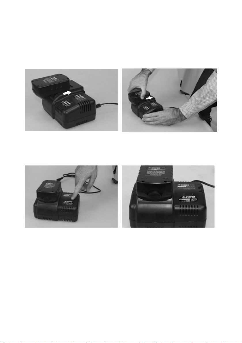
2_INSTRUCCIONES DE PUESTA EN
SERVICIO
COLOCACIÓN
Lea íntegramente estas advertencias de
peligro e instrucciones. En caso de no
atenerse a las advertencias de peligro e
instrucciones siguientes, ello puede oca-
sionar una descarga eléctrica, un incendio
y/o lesión grave.
UTILIZACIÓN REGLAMENTARIA
La herramienta eléctrica ha sido diseñada para apre-
tar y aojar tornillos, para taladrar madera, metal,
cerámica y plástico y para taladrar con percusión en
ladrillo, hormigón y piedra.
DESCRIPCIÓN ILUSTRADA
La numeración de los componentes está referida a
la imagen de la herramienta eléctrica en la página
ilustrada.
1 Punta de atornillar.
2 Portabrocas de sujeción rápida.
3 Anillo de ajuste para preselección del par.
4 Selector de velocidad.
5 Acumulador.
6 Bombilla “Power Light”
7 Selector de sentido de giro / interruptor táctil
PBL202BL/PBL204BL.
8 Interruptor de conexión/desconexión / interruptor
táctil inverso PBL202BL/PBL204BL
9 Botón de extracción del acumulador.
10 Indicador del estado de carga del acumulador.
11 Botón de indicación de carga del acumulador.

-10 -
es
INFORMACIÓN SOBRE RUIDOS Y
VIBRACIONES
Fije unas medidas de seguridad adicionales para pro-
teger al usuario de los efectos por vibraciones como
por ejemplo: Mantenimiento de la herramienta eléctri-
ca y de los útiles, conservar calientes las manos orga-
nización de las secuencias de trabajo.
CARACTERÍSTICAS TÉCNICAS
= Batería
= Voltaje
= Energía de la batería
= Tiempo de carga
= Giros en vacío
= Par de apriete
= Percusiones
= Corte en madera
= Corte en acero
= Corte en piedra
= Peso
= Nivel de potencia acústica
= Nivel de presión acústica
= Vibración
Estos datos son válidos para tensiones nominales de
[U] 230/240 V ~ 50/60 Hz - 110/120 V ~ 60 Hz. Los
valores pueden variar si la tensión fuese inferior, y en
las ejecuciones especícas para ciertos países.
DECLARACIÓN DE CONFORMIDAD CE
El que suscribe:
STAYER IBERICA, S.A.
Con dirección:
Calle Sierra de Cazorla, 7
Área Empresarial Andalucía - Sector 1
28320 PINTO (MADRID)
Tel.: +34 902 91 86 81
CERTIFICA
Que las máquinas:
Tipo: Atornilladores a batería
Declaramos bajo nuestra responsabilidad, que el pro-
ducto descrito bajo “Datos técnicos” está en confor-
midad con las normas o documentos normalizados
siguientes: EN 62841-2-1, EN 62841-2-2, EN 55014-
1, EN 55014-2, EN 61000-3-2, EN 61000-3-3, EN IEC
63000 de acuerdo con las regulaciones 2006/42/EC,
2014/30/EU, 2011/65/EU.
Ramiro de la Fuente
Director Manager
Enero 2021
MONTAJE
Carga del acumulador
Únicamente use los cargadores que se detallan
en la página con los accesorios. Solamente es-
tos cargadores han sido especialmente adaptados a
los acumuladores de iones de litio empleados en su
herramienta eléctrica.
Observación: El acumulador se suministra parcial-
mente cargado. Con el n de obtener la plena poten-
cia del acumulador, antes de su primer uso, cárguelo
completamente en el cargador.
El acumulador de iones de litio puede recargarse
siempre que se quiera, sin que ello merme su vida
útil. Una interrupción del proceso de carga no afecta
al acumulador.
En caso de una desconexión automática
de la herramienta eléctrica no mantenga
accionado el interruptor de conexión/des-
conexión. El acumulador podría dañarse.
Para desmontar el acumulador 5 presione el botón de
extracción 9 y saque el acumulador hacia atrás de la
herramienta eléctrica. No proceda con brusquedad.
Durante la carga del acumulador no es posible conec-
tar la herramienta eléctrica.
El acumulador viene equipado con un sensor de tem-
peratura NTC que solamente admite su recarga dentro
del margen de temperatura entre 0ºC y 45ºC. De esta
manera se alcanza un larga vida útil del acumulador.
Observe las indicaciones referentes a la eliminación.
CAMBIO DE ÚTIL (EXCEPTO MODELOS(02-204)
Antes de cualquier manipulación en la herramien-
ta eléctrica (p.ej. en su mantenimiento, cambio de
útil, etc.), así como al transportarla o guardarla,
colocar en posición central el selector de sentido
de giro.
Vd. podría accidentarse en caso de un accionamiento
fortuito del interruptor de conexión /desconexión.
Gire el portabrocas de sujeción rápida 2 en el sentido
lo suciente, para poder alojar el útil.
Inserte el útil.
Gire rmemente a mano, en el sentido , el casquillo
del portabrocas de sujeción rápida 2. El portabrocas
queda enclavado así de forma automática.
Para desmontar el útil, es preciso desenclavar el por
tabrocas girando el casquillo en sentido contrario.
3_OPERACIÓN
PUESTA EN MARCHA (EXCEPTO MODELOS 202-204)
Montaje del acumulador
Solamente utilice acumuladores de iones de litio
originales Stayer de la tensión indicada en la placa
de características de su herramienta eléctrica.
rpm
ipm
rpm
ipm

- 11 -
es
it
gb
fr
p
tr
gr
de
cz
El uso de otro tipo de acumuladores puede provo-
car daños e incluso un incendio.
Colocar el selector del sentido de giro 7 en la posición
central para evitar una conexión involuntaria. Extraer
el acumulador de la maquina presionando el seguro 9
mientras se tira hacia fuera del acumulador 5. Insertar
el acumulador 5 cargado en la empuñadura hasta que
enclave de manera perceptible y quede enrasado con
la empuñadura.
Ajuste del sentido de giro
Con el selector 7 puede invertirse el sentido de giro
actual de la herramienta eléctrica. Esto no es posible,
sin embargo, con el interruptor de conexión/desco-
nexión 8 accionado.
Giro a derechas: Para taladrar y enroscar tornillos
presionar hasta el tope hacia la izquierda el selector
de sentido de giro 7.
Preselección del par de giro / Ajuste del modo de
operación
Con el anillo de ajuste para la preselección del par 3
puede ajustar el par de giro precisado en 16 niveles
diferentes. Si el ajuste es correcto, el útil se detiene
en el momento en que la cabeza del tornillo quede
enrasada con el material, o bien, al alcanzarse el par
de giro ajustado.
Al desenroscar tornillos, puede que sea necesario
ajustar un nivel de par más alto, o bien, seleccione el
símbolo “Taladrar”.
Taladrar
Gire el selector 3 hacia la posición con el símbolo
“Taladrar sin percutir”.
En la posición “Taladrar” se desactiva el embrague
limitador.
Taladrado con percusión "P"
(PBL0000PK - BL000PK)
Gire el selector 3 hacia la posición con el símbolo
“Taladrar con percusión”.
En la posición “Percutir” se encuentra desactivado el
embrague limitador disponiéndose en todo momento
de la plena potencia.
Selector de velocidad mecánico
Solamente accione el selector de velocidad 4 con
la herramienta eléctrica detenida.
El selector de velocidad 4 permite ajustar 2 campos
de revoluciones.
Velocidad :I
Campo de bajas revoluciones; para atornillar o reali-
zar perforaciones grandes.
Velocidad II:
Campo de altas revoluciones, para perforaciones
pequeñas.
Si el selector de velocidad 4 no pudiese girarse hasta
el tope, gire ligeramente a mano el husillo.
CONEXIÓN/DESCONEXIÓN
Para la puesta en marcha de la herramienta eléctrica
accionar y mantener en esa posición el interruptor de
conexión/desconexión 8.
Según la presión que se ejerza en el gatillo se con-
seguirá mayor o menor velocidad en la herramienta.
La bombilla 6 se enciende al presionar levemente, o
del todo, el interruptor de conexión/desconexión 8, lo
cual permite iluminar el área de trabajo en lugares con
poca luz.
Para desconectar la herramienta eléctrica soltar el in-
terruptor de conexión/desconexión 8.
CONEXIÓN/ DESCONEXIÓN
PBL202BL/PBL204BL
- Mantenga la herramienta de forma natural, con el
dedo índice sobre el panel táctil hacia adelante 7 y su
dedo corazón en el panel táctil inverso 8.
- Presione ligeramente los botones táctiles7-8 al mis-
mo tiempo. Tanto la luz del trabajo del LED y indica-
dor de energía restante se iluminará durante unos
segundos.
- Suelte los dedos hacia delante 7 y almohadillas re-
vertir 8. La herramienta pasado los 5 min, entra en un
modo reposo, para desactivarlo debe volver a presio-
nar ambos botones táctiles 7-8 y así estará lista para
su uso.
- Los botones son sensibles a la presión según la pre-
sión ejercida en 7 u 8 se regulará la velocidad en la
herramienta.
Pulsar 11 para ver estado de carga de la batería.
LED Capacidad
Luz verde > 60%
Luz amarrillo/naranja 30-60%
Luz rojo < 30%
Instrucciones para la operación
Solamente aplique la herramienta eléctrica desco-
nectada contra el tornillo. Los útiles en rotación
pueden resbalar.
Consejos prácticos.
En caso de trabajar prolongadamente a bajas revo-
luciones y con alto par de apriete deberá refrigerarse
la herramienta eléctrica dejándola funcionar aprox. 3
minutos a l as revoluciones en vacío máximas.
Para taladrar en metal solamente usar brocas HSS
(HSS=acero de corte rápido de alto rendimiento) bien
aladas y en perfecto estado. Brocas con la calidad
correspondiente las encontrará en el programa de
accesorios Stayer.
Antes de enroscar tornillos grandes y largos en mate-
riales duros deberá taladrarse un agujero con el diá-
metro del núcleo de la rosca a una profundidad aprox.
correspondiente a 2/ 3 de la longitud del tornillo.

- 12 -
es
4_MANTENIMIENTO Y SERVICIO
MANTENIMIENTO Y LIMPIEZA
Antes de cualquier manipulación en la herramien-
ta eléctrica (p.ej. en su mantenimiento, cambio de
útil, etc.), así como al transportarla o guardarl a,
colocar en posición central el selector de sentido
de giro.
Vd. podría accidentarse en caso de un accionamien-
to fortuito del interruptor de conexión/ desconexión.
Mantenga limpia la herramienta eléctrica y las rejillas
de refrigeración para trabajar con ecacia y seguridad.
Si el acumulador fuese inservible diríjase a un servi-
cio técnico autorizado para herramientas eléctricas
Stayer.
Si a pesar de los esmerados procesos de fabricación
y control, la herramienta eléctrica llegase a averiarse,
la reparación deberá encargarse a un servicio técnico
autorizado para herramientas eléctricas Stayer.
TRANSPORTE
El acumulador ha sido ensayado conforme al manual
UN ST/SG/AC.10/11/Rev.4 Parte III, Subinciso 38.3.
Dispone de una ecaz protección contra una sobre-
presión o cortocircuito interior, así como de unos dis-
positivos contra la rotura forzada o corrientes inversas
peligrosas.
La cantidad equivalente de litio que contiene el acu-
mulador es inferior a los valores límite pertinentes.
Es por ello, por lo que el acumulador, tanto si va suelto
como si va montado en el aparato, no está sujeto a
la s directivas nacionales e internacionales sobre el
transporte de mercancías peligrosas. Sin embargo,
esto si puede ser de relevancia, si son varios los acu-
muladores transportados. En este caso puede que
sea imperativo cumplir ciertas exigencias (p.ej. en el
embalaje)
ELIMINACIÓN
Recomendamos que las herramientas eléctricas, ac-
cesorios y embalajes sean sometidos a un proceso de
recuperación que respete el medio ambiente.
Sólo para los países de la UE:
¡No arroje las herramientas eléctricas a la basura!
Conforme a la Directriz Europea 2012/19/
UE sobre aparatos eléctricos y electrónicos
inservibles, tras su transposición en ley na-
cional, deberán acumularse por separado
las herramientas eléctricas para ser someti-
das a un reciclaje ecológico.
Acumuladores/pilas:
Iones de Litio:
Observe las indicaciones comprendidas
en el apartado “Transporte”
No arroje los acumuladores/pilas a la basura, ni al fue-
go, ni al agua. Los acumuladores/pilas deberán guar-
darse y reciclarse o eliminarse de manera ecológica.
Sólo para los países de la UE:
Conforme a la directriz 2013/56/UE deberán reciclarse
los acumuladores/pilas defectuosos o agotados.

- 13 -
es
it
gb
fr
p
tr
gr
de
cz
Questo manuale è coerente con la data di fabbricazione
del vostro computer, potrete trovare informazioni
sui dati tecnici della macchina acquistata controllo
manuale degli aggiornamenti delle nostremacchine
sul sito: www.grupostayer.com
1_DI SICUREZZA SPECIFICHE
Usare la protezione acustica impiegando trapani
battenti. L’eetto del rumore può causare la perdita
dell’udito.
Utilizzare le impugnature supplementari fornite
insieme all’elettroutensile. La perdita di controllo
sull’elettroutensile può comportare il pericolo di
incidenti.
Tenere l’apparecchio per le superci isolate
dell’impugnatura qual ora venissero eettuati
lavori durante i quali l’accessorio oppure la vite
potrebbe venire a contatto con cavi elettrici
nascosti. Il contatto con un cavo sotto tensione
può mettere sotto tensione anche parti metalliche
dell’apparecchio, causando una scossa elettrica.
Al ne di rilevare linee di alimentazione nascoste,
utilizzare adatte apparecchiature di ricerca oppure
rivolgersi alla locale società erogatrice. Un contatto
con linee elettriche può provocare lo sviluppo di incendi
e di scosse elettriche. Danneggiando linee del gas si
può creare il pericolo di esplosioni. Penetrando una
tubazione dell’acqua si provocano seri danni materiali.
Spegnere immediatamente l’elettroutensile
quando l’utensile accessorio si blocca. Aspettarsi
sempre alti momenti di reazione che possono
provocare un contraccolpo. L’utensile accessorio si
blocca quando:
– l’ elettroutensile è sottoposto a sovraccarico oppure
– pr ende angolature improprie nel pezzo in
lavorazione.
Tenere sempre ben saldo l’elettroutensile.
Serrando a fondo ed allentando le viti è possibile
che si verichino temporaneamente alti momenti di
reazione.
Assicurare il pezzo in lavorazione. Un pezzo in
lavorazione può essere bloccato con sicurezza in
posizione solo utilizzando un apposito dispositivo di
serraggio oppure una morsa a vite e non tenendolo
con la semplice mano.
Mantenere pulita la propria zona di lavoro.
Miscele di materiali di diverso tipo possono risultare
particolarmente pericolose. La polvere di metalli
leggeri può essere inammabile ed esplosiva.
Prima di posare l’elet troutensile, attendere sempre
no a quando si sarà fermato completamente.
L’accessorio può incepparsi e comportare la perdita di
controllo dell’elettroutensile.
Non aprire la batteria. Vi è il pericolo di un corto
circuito.
Proteggere la batteria ricaricabile da
calore troppo forte, p. es . anche da
continue radiazioni solari e dal fuoco. Vi è
concreto pericolo di esplosione!
In caso di difetto e di uso improprio della batteria
ricaricabile vi è il pericolo di una fuoriuscita di
vapori. Far entrare aria fresca e farsi visitare da un
medico in caso di disturbi. I vapori possono irritare
le vie respiratorie.
In caso di batterie difettose vi può essere una
fuoriuscita di liquidi che possono umettare oggetti
vicini. Controllare le relative parti. Pulire queste
parti e, se il caso, sostituirle.
Utilizzare la batteria ricaricabile esclusivamente
insieme all’elettroutensile Stayer. Solo in questo
modo la batteria ricaricabile viene protetta da
sovraccarico pericoloso.
2_DESCRIZIONE DEL FUNZIONAMENTO
IL POSIZIONAMENTO E FISSAGGIO DELLA
MACCHINA
Leggere tutte le avvertenze di pericolo e
le istruzioni operative. In caso di mancato
rispetto delle avvertenze di pericolo e delle
istruzioni operative si potrà creare il
pericolo di scosse elettriche, incendi e/o
incidenti gravi.
COMPONENTI ILLUSTRATI
1 Bit cacciavite
2 Mandrino autoserrante
3 Anello di regolazione preselezione della coppia
4 Commutatore di marcia
5 Batteria ricaricabile
6 Illuminazione del punto di avvitatura «PowerLight»
7 Commutatore del senso di rotazione/Tapswitch
PBL202BL/PBL204BL
8 Interruttore di avvio/arresto / tocco interruttore di
inversione PBL202BL/PBL204BL
9 Tasto di sbloccaggio della batteria ricaricabile
10 Indicatore dello stato di carica della batteria
11 Pulsante Indicatore di ricarica della batteria
La numerazione dei componenti illustrati si riferisce
all’illustrazione dell’elettroutensile che si trova sulla
pagina con la rappresentazione graca

it
-14 -
INFORMAZIONI SULLA RUMOROSITÀ E SULLA
VIBRAZIONE
Adottare misure di sicurezza supplementari per la
protezione dell’operatore dall’eetto delle vibrazioni
come p. es:. manutenzione dell’elettroutensile e
degli accessori, mani calde, organizzazione dello
svolgimento del lavoro.
DATI TECNICI
rpm
ipm
= Batería
= Voltaje
= Energía de la batería
= Tiempo de carga
= Giros en vacío
= Par de apriete
= Percusiones
= Corte en madera
= Corte en acero
= Corte en piedra
= Peso
= Nivel de potencia acústica
= Nivel de presión acústica
= Vibración
Le caratteristiche si riferiscono a tensioni nominali
[U] 230/240V - 50/60 Hz- 110/120 V-60Hz. In caso di
tensioni minori ed in caso di modelli speciali a seconda
dei Paesi,le caratteristiche riportate pos sono essere
divergenti.
DICHIARAZIONE DI CONFORMITÀ
Il sottoscritto: STAYER IBERICA, S.A.
Con indirizzo a: Calle Sierra de Cazorla, 7
Área Empresarial Andalucía - Sector 1
28320 PINTO (MADRID)
Tel.: +34 91 691 86 30
CERTIFICA
Che la macchina:
Tipo: Trapano avvitatore a batteria
Noi dichiariamo sotto la nostra unica e sola
responsabilità che questo prodotto si trova in
conformità con le norme o i documenti normalizzati
seguenti: EN 62841-2-1, EN 62841-2-2, EN 55014-1,
EN 55014-2, EN 61000-3-2, EN 61000-3-3, EN IEC
63000 in conformità con i regolamenti 2006/42/EC,
2014/30/EU, 2011/65/EU.
Ramiro de la Fuente
Direttore generale
Gennaio 2021
MONTAGGIO
Caricare la batteria
Utilizzare esclusivamente stazioni di ricarica per
batterie riportate sulla pagina con gli accessori.
Soltanto queste stazioni di ricarica per batterie sono
adattate alle batterie in ioni di litio utilizzate nell’elet-
troutensile in dotazione.
Nota bene: La batteria ricaricabile viene fornita par-
zialmente carica. Per garantire l’intera potenza della
batteria ricaricabile, prima del primo impiego ricaricare
completamente la batteria ricaricabile nella stazione di
ricarica.
La batteria ricaricabile a ioni di litio può essere rica-
ricata in qualsiasi momento senza ridurne la durata.
Un’interruzione dell’operazione di ricarica non danne-
ggia la batteria ricaricabile.
Dopo la disattivazione automatica de-
ll’elettroutensile non continuare a preme-
re l’interruttore di avvio/ arresto. La batte-
ria ricaricabile potrebbe subire dei danni.
Per estrarre la batteria ricaricabile 5 premere il tasto
di sbloccaggio 9 ed estrarre la batteria ricaricabile da-
ll’elettroutensile verso la parte posteriore. Così facen-
do, non esercitare forza eccessiva.
La batteria ricaricabile è dotata di un sensore NTC per
il controllo della temperatura che permette operazioni
di ricarica solo entro un campo di temperatura tra 0ºC
e 45ºC. In questo modo si permette di raggiungere una
lunga durata della batteria.
Si prega di attenersi alle indicazioni relative allo
smaltimento.
CAMBIO DEGLI UTENSILI
Prima di eettuare lavori all’elettroutensile (ad es.
lavori di manutenzione, cambio d’utensile, ecc.),
nonché in caso di trasporto e di conservazione
dello stesso, avere sempre cura di portare in posi-
zione media il commutatore per la reversibilità. In
difetto, sussisterà il pericolo di lesioni in caso di azio-
namento accidentale dell’interruttore di avvio/
di arresto.
Aprire il mandrino autoserrante 2 ruotando nel senso
di rotazione no a quando l’utensile può essere inseri-
to. Inserire l’utensile.
Ruotare manualmente con forza la boccola del man-
drino autoserrante 2 nel senso di rotazione.
In questo modo il mandrino viene bloccato
automaticamente.
Per sbloccarlo di nuovo quando si intende togliere
l’utensile accessorio, si gira la boccola anteriore in
senso contrario.

- 15 -
es
it
gb
fr
p
tr
gr
de
cz
ASPIRAZIONE POLVERE/ASPIRAZIONE
TRUCIOLI
Polveri e materiali come vernici contenenti piombo, al-
cuni tipi di legname, minerali e metalli possono essere
dannosi per la salute. Il contatto oppure l’inalazione
delle polveri possono causare reazioni allergiche e/o
malattie delle vie respiratorie dell’operatore oppure
delle persone che si trovano nelle vicinanze.
Determinate polveri come polvere da legname di fa-
ggio o di quercia sono considerate cancerogene,
in modo particolare insieme ad additivi per il tratta-
mento del legname (cromato, protezione per legno).
Materiale contenente amianto deve essere lavorato
esclusivamente da personale specializzato.
– Pr o vvedere per una buona aerazione del posto di
lavoro.
– Si c onsiglia di portare una mascherina protettiva
con classe di ltraggio P2.
Osservare le norme in vigore nel Vostro paese se per
i materiali da lavorare.
3_USO
MESSA IN FUNZIONE
Applicazione della batteria ricaricabile
Utilizzare esclusivamente batterie agli ioni di litio
originali Stayer dotate della tensione riportata
sulla targhetta di costruzione dell’elettroutensile
in dotazione. L’impiego di batterie diverse da quelle
consigliate potrà comportare il pericolo di lesione o
d’incendio.
Mettere il commutatore del senso di rotazione 7
in posizione centrale in modo da impedire che
la macchina possa accendersi accidentalmente.
Applicare la batteria ricaricata 5 nell’impugnatura no
a percepirne lo scatto d’innesto ed a farla trovare a lo
con l’impugnatura.
Impostazione del senso di rotazione
Con il commutatore del senso di rotazione 7 è possibile
modicare il senso di rotazione dell’elettroutensile.
Comunque, ciò non è possibile quando l’interruttore di
avvio/arresto 8 è premuto.
Rotazione destrorsa: Per forare ed avvitare viti
premere il commutatore del senso di rotazione 7 verso
sinistra no all’arresto.
Preselezione della coppia / Regolazione del modo
operativo
Con l’anello di regolazione per la preselezione della
coppia 3 è possibile regolare la coppia richiesta su 10
livelli . Se la coppia è ben regolata, l’elettroutensile si
ferma non appena la testa della vite arriva ad essere a
lo con la supercie del materiale oppure si raggiunge
la coppia impostata.
Per svitare viti, regolare eventualmente su un livello
maggiore oppure regolare sul simbolo «Foratura».
Foratura
Ruotare l’anello di regolazione 3 sul simbolo «foratura
non battente».
Alla posizione «Foratura» il disinserimento automatico
è disattivato.
Foratura battente"P"
(PBL0000PK - BL000PK)
Mettere l’anello di regolazione 3 sul simbolo «foratura
battente».
Alla posizione «foratura battente» il disinserimento
automatico è disattivato e la macchina raggiunge
sempre il massimo della prestazione.
Commutazione meccanica di marcia
Azionare il commutatore di marcia 4 solo quando
l’elettroutensile è fermo.
Con il commutatore di marcia 4 è possibile
preselezionare 2 campi di velocità.
Marcia I:
Bassa velocità; per avvitare oppure per lavori con
grandi diametri di foratura.
Marcia II:
Alta velocità; per lavori con piccolo diametro di
foratura.
In caso non fosse possibile spostare il commutatore
di marcia 4 no alla battuta, girare leggermente il
mandrino di trasmissione tramite la punta.
Accendere/spegnere
Per accendere l’elettroutensile premere l’interruttore di
avvio/arresto 8 e tenerlo premuto.
La lampadina 6 è illuminata in caso di interruttore di
avvio/arresto 8 premuto leggermente oppure premuto
completamente e consente l’illuminazione del settore
di lavoro in caso di condizioni di luce sfavorevoli.
Per spegnere l’elettroutensile rilasciare di nuovo
l’interruttore di avvio/arresto 8
Log In / Out PBL202BL / PBL204BL
- Tenere lo strumento in modo naturale, con il dito
indice sul pannello a soramento 7 in avanti e il suo
cuore nel pannello a soramento dito inversa 8.
- Premere leggermente i pulsanti contemporaneamente
táctiles 7-8. Sia la luce del lavoro del LED e indicatore
dell'energia residua si illumina per alcuni secondi.
- Rilasciare le dita in avanti retromarcia pastiglie
7 e 8. Gli ultimi 5 min strumento entra in modalità
sleep, per disattivarlo è necessario premere due tasti
programmabili 7-8 e quindi pronto per l'uso.
- I tasti sono sensibili alla pressione in base al tasso
di pressione 7 o 8 deve essere impostato all'interno
dello strumento.

it
- 16 -
Freno di arresto graduale
Rilasciando l’interruttore avvio/arresto 8 il mandrino
autoserrante viene frenato impedendo in questo modo
una fase di arresto dell’utensile accessorio.
Avvitando viti, rilasciare l’interruttore avvio/arresto 8
solo dopo che la vite sia stata avvitata a lo nel pezzo
in lavorazione. In questo caso la testa della vite non
penetra nel pezzo in lavorazione.
LED Autonomia
Luce verde > 60%
Luce giallo 30-60%
Luce rosso < 30%
INDICAZIONI OPERATIVE
Applicare l’elettroutensile sulla vite soltanto
quando è spento. Utensili accessori in rotazione
possono scivolare.
Suggerimenti
In seguito a lunghe operazioni di lavoro a bassa
velocità, per farlo rareddare, lasciar ruotare
l’elettroutensile in funzionamento a vuoto per ca. 3 mi
nuti alla massima velocità.
Per forature nel metallo impiegare solo punte HSS
perfettamente alate (HSS = acciaio superrapido).
Una rispettiva qualità viene garantita dal programma
accessori Stayer.
Volendo avvitare viti di dimensioni maggiori in
materiale duro, eseguire prima un foro pari al diametro
interno del letto e per circa 2/ 3 della lunghezza
completa della vite.
4_MANUTENZIONE ED ASSISTENZA
MANUTENZIONE E PULIZIA
Prima di eettuare lavori all’elettroutensile (ad es.
lavori di manutenzione, cambio d’utensile, ecc.),
nonché in caso di trasporto e di conservazione
dello stesso, avere sempre cura di portare in po-
sizione media il commutatore per la reversibilità.
In difetto, sussisterà il pericolo di lesioni in caso di
azionamento accidentale dell’interruttore di avvio/di
arresto.
Per poter garantire buone e sicure operazioni di
lavoro, tenere sempre puliti l’elettroutensile e le
prese di ventilazione.
Se la batteria ricaricabile non dovesse più funzionare,
rivolgersi ad un Centro per il Servizio Clienti
elettroutensili Stayer autorizzato.
Se nonostante gli accurati procedimenti di produzione
e di controllo l’elettroutensile dovesse guastarsi,
la riparazione va fatta eettuare da un punto di
assistenza autorizzato per gli elettroutensili Stayer.
In caso di richieste o di ordinazione di pezzi di ricambio,
comunicare sempre il codice prodotto a 10 cifre riporta
to sulla targhetta di fabbricazione dell’elettroutensile!
TRASPORTO
La batteria ricaricabile è stata collaudata secondo il
manuale UN [Recommendations on the Transport of
Dangerous Goods, Manual of Tests and Criteria] ST/
SG/AC.10/11/Rev.4 Parte III , sottoparagrafo 38.3.
Essa è dotata sia di un’ecace protezione contro la
sovrappressione interna e pericolo di corto circuito che
di dispositivi adatti ad impedirne una rottura dovuta a
sovraccarico ed il pericolo di corrente inversa.
La quantità di equivalente di litio contenuta nella
batteria ricaricabile si trova al di sotto dei valori di
soglia vigenti. Per questo motivo la batteria ricaricabile
quale singolo elemento o come elemento applicato
in una macchina non rientra tra i prodotti considerati
particolarmente pericolosi nelle norme nazionali o
internazionali. In caso di trasporto di diverse batterie
ricaricabili, può comunque darsi il caso che le norme
relative ai prodotti pericolosi acquistino rilevanza. In
questo caso può essere necessario attenersi alle
speciali condizioni (p. es . l’imballaggio)
SMALTIMENTO
Avviare ad un riciclaggio rispettoso dell’ambiente gli
imballaggi, gli elettroutensili e gli accessori dismessi.
Solo per i Paesi della CE:
Non gettare elettroutensili dismessi tra i riuti
domestici!
Conformemente alla norma della direttiva
UE 2012/19 sui riuti di apparecchiature
elettriche ed elettroniche (RAEE) ed
all’attuazione del recepimento nel diritto
nazionale, gli elettroutensili diventati
inservibili devono essere raccolti separatamente ed
essere inviati ad una riutilizzazione ecologica.
Batterie ricaricabili/Batterie:
Li-Ion:
Si prega di tener presente le indicazioni
riportare nel paragrafo «Trasporto»,
Qualunque sia il tipo di batteria esaurita, essa non
deve essere gettata tra i riuti domestici, nel fuoco o
nell’acqua. Ogni tipo di batteria esaurita deve essere,
riciclata oppure smaltita rispettando rigorosamente la
protezione dell’ambiente.
Solo per i Paesi della CE:
Ogni tipo di batteria difettosa oppure esaurita deve
essere riciclata secondo la direttiva 2013/56/EU.

- 17 -
es
it
gb
fr
p
tr
gr
de
cz
This manual is consistent with the date of manufacture
of your machine, you will nd information on the
technical data of the machine acquired manual check
for updates of our machines on the website:
www.grupostayer.com
1_MACHINE-SPECIFIC SAFETY
WARNINGS
Wear ear protectors when impact drilling. Exposure
to noise can cause hearing loss.
Use auxiliary handle(s), if supplied with the tool.
Loss of control can cause personal injury.
Hold power tool by insulated gripping surfaces,
when performing an operation where the cutting
accessory or fastener may contact hidden wiring.
Cutting accessory and fasteners contacting a “live”
wire may make exposed metal parts of the power tool
“live” and could give the operator an electric shock.
Use appropriate detectors to determine if utility
lines are hidden in the work area or call the local
utility company for assistance. Contact with electric
lines can lead to re and electric shock. Damaging a
gas line can lead to explosion. Penetrating a water
line causes property damage or may cause an electric
shock.
Switch o the power tool immediately when the
tool insert jams. Be prepared for high reaction
torque that can cause kickback.
The tool insert jams when:
— The power tool is subject to overload or
— It becomes wedged in the workpiece.
Hold the machine with a rm grip. High reaction
torque can briey occur while driving in and loosening
screws.
Secure the workpiece. A workpiece clamped with
clamping devices or in a vice is held more secure than
by hand.
Keep your workplace clean. Blends of materials are
particularly dangerous. Dust from light alloys can burn
or explode.
Always wait until the machine has come to a
complete stop before placing it down. The tool
insert can jam and lead to loss of control over the
power tool.
Do not open the battery. Danger of shortcircuiting.
Protect the battery against heat, e. g., also
against continuous sun irradiation and re.
There is danger of explosion.
In case of damage and improper use of the battery,
vapours may be emitted. Provide for fresh air
and seek medical help in case of complaints. The
vapours can irritate the respiratory system.
When the battery is defective, liquid can escape
and come into contact with adjacent components.
Check any parts concerned. Clean such parts or
replace them, if required.
Use the battery only in conjunction with your
Stayer power tool. This measure alone protects the
battery against dangerous overload.
2_FUNCTIONAL DESCRIPTION
PLACING OR FIXING THE TOOL
Read all safety warnings and all
instructions. Failure to follow the warnings
and instructions may result in electric
shock, re and/or serious injury.
PRODUCT FEATURES
The numbering of the product features refers to the
illustration of the machine on the graphics page.
1 Screwdriver bit
2 Keyless chuck
3 Torque preselection ring
4 Gear selector
5 Battery
6 “Power Light”
7 Rotational direction switch/Forward Touch Pad
PBL202BL/PBL204BL
8 On/O switch / Reverse Touch Pad PBL202BL/
PBL204BL
9 Battery unlocking button
10 Battery charge-control indicator
11 Button battery charging indication
NOISE/VIBRATION INFORMATION
Identify additional safety measures to protect the ope-
rator from the eects of vibration such as: maintain the
tool and the accessories, keep the hands warm, orga-
nisation of work patterns.

gb
-18 -
TECHNICAL SPECIFICATIONS
rpm
ipm
= Battery
= Voltage
= Battery power
= Battery charging time
= No load speed
= Tightening torque
= Percussions
= Wood drilling capacity
= Steel drilling capacity
= Stone drilling capacity
= Weight
= Sound power level
= Sound pressure level
= Vibration
The values given are valid for nominal voltages
[U]230/240 V-50/60 Hz - 110/120 V - 60Hz. For lower
voltage and models for specic countries, these
values can vary.
DECLARATION OF CONFORMITY
The undersigned: STAYER IBERICA, S.A.
With address at:
Calle Sierra de Cazorla, 7
Área Empresarial Andalucía - Sector 1
28320 PINTO (MADRID)
Tel.: +34 91 691 86 30
CERTIFIES
That the machine:
Type: Cordless drill/screwdriver
We declare under our sole responsibility that this
product is in conformity with the following standards
or standardized documents: EN 62841-2-1, EN
62841-2-2, EN 55014-1, EN 55014-2, EN 61000-
3-2, EN 61000-3-3, EN IEC 63000 according to EU
Regulations 2006/42/EC, 2014/30/EU, 2011/65/EU.
Ramiro de la Fuente
Director General
January 5, 2021
3_ASSEMBLY
BATTERY CHARGING
Use only the battery chargers listed on the
accessories page. Only these battery chargers are
matched to the lithium ion battery of your power tool.
Note: The battery is supplied partially charged. To
ensure full capacity of the battery, completely charge
the battery in the battery charger before using your
power tool for the rst time.
The lithium ion battery can be charged at any time wi-
thout reducing its service life. Interrupting the charging
procedure does not damage the battery.
Do not continue to press the On/O
switch after the machine has been
automatically switched o. The battery can
be damaged.
To remove the battery 5, press the battery unlocking
button 9 and pull the battery out of the power tool
toward the rear. Do not exert any force.
The battery is equipped with a NTC temperature control
which allows charging only within a temperature range
of between 0º C and 45º C. A long battery service life
is achieved in this manner.
Observe the notes for disposal.
CHANGING THE TOOL(not aply to 202-204 models)
Before any work on the machine (e. g.,maintenance,
tool change, etc.) as well as during transport and
storage, set the rotational direction switch to the
centre position. Unintentional actuation of the On/O
switch can lead to injuries.
Open the keyless chuck 2 by turning in rotation
direction , until the tool can be inserted. Insert the tool.
Firmly tighten the collar of the keyless chuck 2 by hand
in rotation direction . This automatically locks the drill
chuck.
The locking is released again to remove the tool when
the collar is turned in the opposite direction.
DUST/CHIP EXTRACTION
Dusts from materials such as lead-containing coatings,
some wood types, minerals and metal can be harmful
to one’s health. Touching or breathing-in the dusts
can cause allergic reactions and/or lead to respiratory
infections of the user or bystanders.
Certain dusts, such as oak or beech dust, are
considered as carcinogenic, especially in connection
with woodtreatment additives (chromate, wood
preservative). Materials containing asbestos may only
be worked by specialists.
– Pro v ide for good ventilation of the working place.
– It i s recommended to wear a P2 lterclass respirator.
Observe the relevant regulations in your country for
the materials to be worked.

- 19 -
es
it
gb
fr
p
tr
gr
de
cz
4_OPERATION
Starting Operation
Inserting the Battery
Use only original Stayer lithium ion batteries with
the voltage listed on the nameplate of your power
tool. Using other batteries can lead to injuries and
pose a re hazard.
Not aply to 202-204 models:
Set the rotational direction switch 7 to the centre
position in order to avoid unintentional starting. Insert
the charged battery 5 into the handle so that it can be
felt to engage and faces ush against the handle.
Reversing the Rotational Direction
The rotational direction switch 7 is used to reverse the
rotational direction of the machine. However, this is not
possible with the On/O switch 8 actuated.
Right Rotation: For drilling and driving in screws, push
the rotati onal direction switch 7 left to the stop.
Setting the Torque / Setting the Operating Mode
The required torque can be preselected in 16 steps
with the torque preselection ring 3. With the correct
setting, the insert tool is stopped as soon as the screw
is screwed ush into the material or when the set
torque is reached.
Select a higher setting when driving out screws, or set
to the symbol “Drilling”.
Drilling
Set the preselection ring 3 to the “Drilling without
impact” symbol.
The safety clutch is deactivated in the “Drilling”
position.
Impact drilling
"P" (PBL0000PK - BL000PK)
Set the preselection ring 3 to the “Impact drilling”
symbol.
In the “Impact drilling” position, the safety clutch
is deactivated and the maximum power is always
eective.
Gear Selection, Mechanical
Actuate the gear selector 4 only when the machine
is at a standstill.
Two speed ranges can be preselected with the gear
selector 4.
Gear I:
Low speed range; for screwdriving or working with
large drilling diameter.
Gear II:
High speed range; for working with small drilling
diameter.
If the gear selector 4 cannot be fully engaged, lightly
rotate the drive spindle with the drill bit by twisting the
drill chuck.
Switching On and O
To start the machine, press the On/O switch 8 and
keep it pressed.
The light 6 is lit when the On/O switch 8 is slightly
or completely pressed in and permits to light the work
area when the lighting conditions are bad.
To switch o the machine, release the On/O switch 8
Start In / Out PBL202BL / PBL204BL
- Keep the tool in a natural way, with the index nger
on the touch panel forward 7 and the middle nger in
the reverse touch panel 8.
- Lightly press the buttons simultaneously tactile 7- 8.
Both LED work light and remaining power indicator will
illuminate for a few seconds.
- Release your ngers forward reverse pads 7 and 8.
The last 5 min tool enters a sleep mode, to disable it
you must push two soft buttons 7- 8 and thus ready
for use.
- The buttons are pressure sensitive in accordance
with the pressure rate 7 or 8 must be set within the
tool.
Run-on Brake
When the Touch pad 7 or 8 for PBL202 & 204 is
released, the chuck brakes to a stop, thus preventing
the run-on of the tool.
When driving in screws, wait until the screw is screwed
in ush with the material and then release the Touch
pad 7 or 8 for PBL202 & 204. By doing so, the head of
the screw does not penetrate into the material.
LED Capacity
Lighting green > 60%
Lighting yellow 30-60%
Lighting red < 30%

gb
- 20 -
WORKING ADVICE
Apply the power tool to the screw only when it is
switched o. Rotating tool inserts can slip o.
Tips
After longer periods of working at low speed, allow the
machine to cool down by running it for approx. 3 mi
nutes at maximum speed with no load.
For drilling in metal, use only perfectly sharpened HSS
drill bits (HSS=high-speed steel). The appropriate
quality is guaranteed by the Stayer accessories
program.
Before screwing larger, longer screws into hard
materials, it is advisable to predrill a pilot hole with the
core diameter of the thread to approx. 2/ 3 of the screw
length.
5_MAINTENANCE AND SERVICE
MAINTENANCE AND CLEANING
Before any work on the machine (e. g.,
maintenance, tool change, etc.) as well as during
transport and storage, set the rotational direction
switch to the centre position.Unintentional actuation
of the On/O switch can lead to injuries.
For safe and proper working, always keep the
machine and ventilation slots clean.
When the battery is no longer operative, please refer
to an authorised after-sales service agent for Stayer
power tools.
If the machine should fail despite the care taken in
manufacturing and testing procedures, repair should
be carried out by an after-sales service centre for
Stayer power tools.
TRANSPORT
The battery is tested according to UN document ST/
SG/AC.10/11/Rev.4 Part III, subsection 38.3. It has
eective protection against internal overpressure and
short circuiting as well as devices for the prevention
of violent rupture and dangerous reverse current ow.
The lithium-equivalent content in the battery is below
applicable limit values. Therefore, the battery is
not subject to national or international regulations
pertaining to dangerous mediums, neither as an
individual component nor when inserted into a
machine. However, the regulations governing
dangerous goods may be relevant when transporting
several batteries. In this case, it can be necessary to
comply with special conditions (e.g., concerning the
packaging).
DISPOSAL
The machine, accessories and packaging should be
sorted for environmental-friendly recycling.
Only for EC countries:
Do not dispose of power tools into house-
hold waste!
According the European Guideline 2012/19/
EU for Waste Electrical and Electronic
Equipment and its imple m e n t a t ion
into national right, power tools that are no longer usa-
ble must be collected separately and disposed of in an
environmentally correct manner.
Battery packs/batteries:
Li-Ion:
Please observe the instructions in sec-
tion “Transport”,
Do not dispose of battery packs/batteries into
household waste, re or water. Battery packs/batteries
should be collected, recycled or disposed of in an
environmental-friendly manner.
Only for EC countries:
Defective or dead out battery packs/batteries must be
recycled according the guideline 2013/56/EU.
This manual suits for next models
29
Table of contents
Languages:
Other stayer Drill manuals

stayer
stayer TH610 User manual

stayer
stayer TM710BA User manual

stayer
stayer TM6B User manual

stayer
stayer TM1000 User manual

stayer
stayer TH610 User manual

stayer
stayer TM6B User manual

stayer
stayer PBL122K User manual

stayer
stayer TM710 User manual

stayer
stayer HD3BEK User manual

stayer
stayer PBL122CPK User manual

stayer
stayer TM800 User manual

stayer
stayer PBL120K User manual

stayer
stayer HDB240K User manual

stayer
stayer 130 User manual

stayer
stayer MULTI DRILL 130 User manual

stayer
stayer TM710BA User manual

stayer
stayer 384B User manual

stayer
stayer PBL222PK User manual

stayer
stayer HD21K User manual

stayer
stayer TM800A User manual