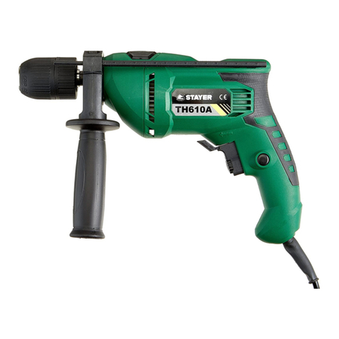
stayer TH610 User manual

www.grupostayer.com
Manual de instrucciones
ES
Área Empresarial Andalucía - Sector I
Calle Sierra de Cazorla nº7
C.P: 28320 Pinto (Madrid) SPAIN
Email: sales@grupostayer.com
Email: info@grupostayer.com
Istruzioni d’uso
IT
Operating instructions
GB
Bedienungsanleitung
DE
Instructions d’emploi
FR
Manual de instruções
P
Kullanma Kılavuzu
TR
TH610
TH610A
TH710A
TH710AK
TH1000AK
Instrukcja obsługi
PL

1
2
2
13
6
5
1
3
7
7
4
8
7

6 7
6
1
8
3
A
B
5
8
4 5
1a
2
9
9

6.1.
TH610
TH610A
TH710A
TH710AK
TH1000AK
W
600
710
1000
-1
min
0-3000
0-3000
0-3000
-1
min
0-41600
0-48000
0-44800
mm.
13
13
13
Ø max
13
13
13
Ø max
16
13
20
Ø max
25
25
25
kg
2
2
2.3
L dB(A)
pA
97,5
89
97,5
L dB(A)
WA
105
95
105
2
a m/s
h
3
3
3
rpm
ipm
K=3 dB
2
K=1.5 m/s
kg

Keep your workplace clean. Blends of materials are
particularly dangerous. Dust from light alloys can burn or
explode.
Always wait until the machine has come to a complete
stop before placing it down. The tool insert can jam and
lead to loss of control over the power tool.
Never use the machine with a damaged cable. Do not
touch the damaged cable and pull the mains plug when
the cable is damaged while working. Damaged cables
increase the risk of an electric shock.
“Caution - Read the operating instructions to
reduce the risk of inquiry”
Wear ear-muffs. The impact of noise can cause
damage to hearing.
Wear a breathing mask.
Dust which is injurious to health can be generated
when working on wood and other materials.
Never use the device to work on any materials
containing asbestos!
Wear safety goggles.
Sparks generated during working or splinters, chips
and dust emitted by the device can cause loss of
sight.
3.Instructions for use
3.1 Placement Tool
Read all safety warnings and all instructions.
Failure to follow the warnings and instructions may
result in electric shock, fire and/or serious injury.
The equipment is to be used only for its prescribed purpose.
Any other use is deemed to be a case of misuse.
The user / operator and not the manufacturer will be liable
for any damage or injuries of any kind caused as a result of
this.
3.2 Assembly
Before you connect the equipment to the mains
supply make sure that the data on the rating plate
are identical to the mains data.
Before any work on the machine itself, pull the
mains plug.
Fitting the additional handle (Fig. 2-3/Item 7)
The additional handle 7 enables you to achieve better
stability whilst using the hammer drill. Do not use the tool
without the additional handle.
The additional handle 7 is secured to the hammer drill by a
clamp. During the handle clockwise tightens this clamp.
Turning it anti-clockwise will release the clamp.
This manual is consistent with the date of manufacture of
your machine, you will find information on the technical data
of the machine acquired manual check for updates of our
machines on the website: www.grupostayer.com
The drill is designed for drilling holes into wood, iron,
non-ferrous metals and rock using the appropriate bits.
1. Contents
page
2.Specific safety instructions........................................9
3.Instructions for use......................................................9
3.1 Placement Tool...............................................................9
3.2 Assembly........................................................................9
3.3 Electrical connection.............................................10
3.4 Illustrated description............................................10
4.Operating instructions..............................................10
4.1 Placement and testing..........................................10
4.2 Tool change..........................................................11
5.Maintenance and service instructions.....................11
5.1 Cleaning...............................................................1 1
5.2 Repair service.......................................................11
5.3 Warranty...............................................................11
5.4 Disposal and recycling..........................................11
6.Regulations................................................................12
6.1 Technical Data......................................................12
6.2 EU declaration of conformity.................................12
2. Specific safety instructions
Wear hearing protection. Exposure to noise can cause
hearing loss.
Always use the auxiliary handle supplied with the
machine. Loss of control can cause personal injury.
Use suitable detectors to determine if utility lines are
hidden in the work area or call the local utility company
for assistance. Contact with electric lines can lead to fire
and electric shock. Damaging a gas line can lead to
explosion. Penetrating a water line causes property
damage or may cause an electric shock.
Hold the power tool only by the insulated gripping
surfaces when performing an operation where the
cutting tool may contact hidden wiring or its own cord.
Contact with a “live” wire will also make exposed metal
parts of the power tool “live” and shock the operator.
When working with the machine, always hold it firmly
with both hands and provide for a secure stance. The
power tool is guided more secure with both hands.
Secure the workpiece. A workpiece clamped with
clamping devices or in a vice is held more secure than by
hand.
Do not work materials containing asbestos. Asbestos is
considered carcinogenic.
Take protective measures when dust can develop
during working that is harmful to one’s health,
combustible or explosive.
Example: Some dusts are regarded as carcinogenic. Wear
a dust mask and work with dust/chip extraction when
connectable.
ENGLISH
5
5
4.Operating instructions
4.1 Placement and testing
6.1 ON/OFF switch (Fig. 7/Item 5)
First fit a suitable drill bit into the tool (see 5.3).
Connect the mains plug to a suitable socket.
Position the drill in the position you wish to drill.
To switch on:
Press the ON/OFF switch 5
Continuous operation:
Secure the ON/OFF switch 5 with the locking button 4.
To switch off:
Press the ON/OFF switch 5 briefly.
Adjusting the speed (Fig. 7/Item 5)
You can infinitely vary the speed whilst using thetool.
Select the speed by applying a greater or lesserpressure to
the ON/OFF switch 5.
Select the correct speed: The most suitablespeed depends
on the workpiece, the type of useand the drill bit used.
Low pressure on the ON/OFF switch 5: Lower speed
(suitable for: small screws and soft materials)
Greater pressure on the ON/OFF switch 5:
Higher speed (suitable for large/long screws and hard
materials)
Tip:
Start drilling holes at low speed. Then increase the speed in
stages.
Benefits:
The drill bit is easier to control when starting the hole and
will not slide away.
You avoid drilling messy holes (for example in tiles).
Preselecting the speed (Fig. 7/Item 6)
The speed setting ring 8 enables you to define the
maximum speed. The ON/OFF switch 5 can only be
pressed to the defined maximum speed setting.
Set the speed using the setting ring 8 on the ON/OFF switch
5.
Do not attempt to make this setting whilst the drill is in use.
Clockwise/Counter-clockwise switch (Fig. 7/Item 6)
Change switch position only when the drill is at a standstill!
Switch the direction of the hammer drill using the
clockwise/counter-clockwise switch (6):
Direction Switch position
Clockwise (forwards and drill) R
Counter-clockwise (reverse) L
Drill / hammer drill selector switch (Fig. 8/Item 3)
Change switch position only when the drill is at a
standstill!
Drill
Drill / hammer drill selector switch 3 in the drill position.
(Position A)
Use for: Wood, metal, plastic
Hammer drill
Drill / hammer drill selector switch 3 in the hammer
drill position. (Position B)
Use for: Concrete, rock, masonry
ENGLISH
6
6
The supplied additional handle 7 must first be fitted. To do
this, the clamp must be opened by turning the handle until it
is wide enough for the additional handle to be slid over the
chuck 1 and on to the hammer drill.
After you have positioned the additional handle 7, turn it to
the most comfortable working position for you.
Now turn the handle in the opposite direction again until the
additional handle is secure.
The additional handle 7 is suitable for both lefthanded and
right-handed users.
Fitting and adjusting the depth stop (Fig. 4/Item 2)
The depth stop 2 is held in place by the additional handle 7
by clamping. The clamp can be released and tightened by
turning the handle. Release the clamp and fit the depth stop
2 in the recess provided for it in the additional handle.
Set the depth stop 2 to the same level as the drill bit.
Pull the depth stop back by the required drilling depth.
Turn the handle on the additional handle 7 until it is secure.
Now drill the hole until the depth stop 2 touches the
workpiece.
Fitting the drill bit (Fig. 5-6)
Always pull the power plug before making adjustments to
the equipment.
The quick-change drill chuck 1 is equipped with a locking
fastener:
To lock = press the sleeve (a) forwards
To unlock = press the sleeve (a) backwards
release depth stop as described in the previous section
and push it towards the additional handle. This provides
free access to the chuck 1.
This hammer drill is fitted with a keyless chuck 1.
Open the chuck 1. The drill bit opening must be large
enough to fit the drill bit into.
Select a suitable drill bit. Push the drill bit as far as possible
into the chuck opening.
Close the chuck 1. Check that the drill bit is secure in the
chuck 1.
Check at regular intervals that the drill bit or tool is secure
(pull the mains plug).
3.3 Electrical connection
Observe correct mains voltage! The voltage of the
power source must agree with the voltage specified on
the nameplate of the machine. Power tools marked with
230 V can also be operated with 220 V.
If the power cable for this equipment is damaged, it must be
replaced by the manufacturer or its aftersales service or
similarly trained personnel to avoid danger.
3.4 Illustrated description
1. Drill chuck
2. Drill depth stop
3. Drill/hammer drill selector switch
4. Locking button
5. ON/OFF switch
6. Clockwise/Counter-clockwise switch
7. Additional handle
8. Speed controller
9. Gear Selection, Mechanical

Important! The carbon brushes should not be rep
laced by anyone but a qualified electrician.
Carbon brushes
In case of excessive sparking, have the carbon brushes
checked only by a qualified electrician.
Important! The carbon brushes should not be replaced by
anyone but a qualified electrician.
Maintenance
There are no parts inside the equipment which require
additional maintenance.
Ordering replacement parts:
Please quote the following data when ordering replacement
parts:
Type of machine
Article number of the machine
Identification number of the machine
Replacement part number of the part required
5.2 Repair service
Our after-sales service responds to your questions
concerning maintenance and repair of your product as well
as spare parts. Exploded views and information on spare
parts can also be found under: info@grupostayer.com
Our customer consultants answer your questions
concerning best buy, application and adjustment of
products and accessories.
5.3 Warranty
Warranty card Included in the documentation that
accompanies this equipment, you should find the warranty
card. You should fill out the card completely and return to
vendor with a copy of purchasing receipt or invoice and you
should receive a receipt.
Note: If you cannot find the warranty card within the
documentation, you must ask for it through your supplier.
The warranty is limited only to manufacturing defects and
expire if pieces have been removed or manipulated or
repaired other than the manufacturer.
5.4 Disposal and recycling
The machine, accessories and packaging should be sorted
for environmental-friendly recycling.
Only for EC countries:
Do not dispose of power tools into household waste!
According the European Guideline 2002/96/EC
for Waste Electrical and Electronic Equipment
and its implementation into national right, power
tools that are no longer usable must be collected
separately and disposed of in an environmentally
correct manner.
Subject to change without notice.
Tips for working with your hammer drill
Drilling concrete and masonry
Switch the Drill/Hammer drill selector switch 3 to position B
(Hammer drill).
Always use carbide drill bits and a high speed setting for
drilling into masonry and concrete.
Drilling steel
Switch the drill / hammer drill selector switch 3 to position A
(drill).
Always use HSS drill bits (HSS = high speed steel) and a
low speed setting for drilling steel.
We recommend that you lubricate the hole with a suitable
cutting fluid to prevent unnecessary drill bit wear.
Inserting/Removing screws
Switch the Drill/Hammer drill selector switch (3) to position
A (drill).
Use a low speed setting
Starting holes
If you wish to drill a deep hole in a hard material
(such as steel), we recommend that you start the
hole with a smaller drill bit.
Taladrar en baldosas y azulejos
Poner el conmutador 3 en la posición A (taladro).
Drilling tiles
To start the hole, switch the drill / hammer drill selector
switch 3 to position A (drill).
Switch the drill / hammer drill selector switch 3 to position B
(hammer drill) as soon as the drill bit has passed through
the tiles.
4.2 Tool change
To avoid damaging the gearbox, the drill / hammer drill
selector switch should only be moved when the machine is
at a standstill.
5.Maintenance and service instructions
Before any work on the machine itself, pull the mains
plug.
5.1 Cleaning
Keep all safety devices, air vents and the motor housing
free of dirt and dust as far as possible.
Wipe the equipment with a clean cloth or blow it with
compressed air at low pressure.
We recommend that you clean the device immediately
each time you have finished using it.
Clean the equipment regularly with a moist cloth and some
soft soap. Do not use cleaning agents or solvents; these
could attack the plastic parts of the equipment. Ensure that
no water can seep into the device.
Carbon brushes
In case of excessive sparking, have the carbon brushes
checked only by a qualified electrician.
ENGLISH
7
7

6.Regulations
6.1 Technical Data
= Rated power input
= Load speed
= Percussion
= Diameter of drill
= Maximum drilling, steel
= Maximum drilling, stone
= Maximum drilling, wood
= Weight
L = Sound power level
WA
A
L = Sound pressure level
P
= Vibration
The values given are valid for nominal voltages [U] 230/240 V ~
50/60 Hz - 110/120 V ~ 60Hz. For lower voltage and models for
specific countries, these values can vary. Please observe the
article number on the type plate of your machine. The trade names
of the individual machines may vary.
Noise/Vibration Information
Sound and vibration values were measured in accordance
with EN 60745.
¡ !Wear hearing protection
Sound pressure level, L 97,5 dB(A)
pA
Uncertainty K 3 dB
pA
Sound power level L 105 dB(A)
WA
Uncertainty K 3 dB
WA
Wear ear-muffs.
The impact of noise can cause damage to hearing.
Total vibration values (vector sum of three directions)
determined in accordance with EN 60745.
Hammer drilling into concrete (handle)
Vibration emission value a = 13,7 m/s²
h
Uncertainty K = 1,5 m/s²
Hammer drilling in concrete (additional handle)
2
Vibration emission value a = 10,910 m/s
h
2
K uncertainty = 1,5 m/s
Drilling into metal (handle)
Vibration emission value a = 4,503 m/s²
h
Uncertainty K = 1,5 m/s²
Drilling in metal (additional handle) 2
Vibration emission value a = 5,372 m/s
h
2
Imprecisión K = 1,5 m/s
Important!
El valor de las vibraciones cambia dependiendo del ámbito
de aplicación de la herramienta eléctrica, por lo que en
casos excepcionales puede superar al valor indicado.
6.2 EU declaration of conformity
The undersigned:
STAYER IBERICA, S.A.
With address at:
Calle Sierra de Cazorla, 7
Área Empresarial Andalucía - Sector 1
28320 PINTO (MADRID)
Tel.: +34 902 91 86 81 / Fax: +34 91 691 91 72
CERTIFIES
That the machine:
Type: DRILLS / DRILLS / HAMMERS
Models: TH610 / TH610A / TH710A / TH710AK /
TH1000AK
We declare under our sole responsibility that this product is
in conformity with the following standards or standardized
documents:
EN 60745-1, EN 60745-2-1, EN 55014-1, EN 55014-2, EN
61000-3-2, EN 61000-3-3 according to EU Regulations
2006/42/EC, 2014/30/EU.
ENGLISH
8
8
rpm
ipm
kg
Ramiro de la Fuente
Managing Director
January, 2018

www.grupostayer.com
Área Empresarial Andalucía - Sector I
Calle Sierra de Cazorla nº7
C.P: 28320 Pinto (Madrid) SPAIN
Email: sales@grupostayer.com
Email: info@grupostayer.com
Other manuals for TH610
2
This manual suits for next models
4
Table of contents
Other stayer Drill manuals

stayer
stayer TE35A User manual

stayer
stayer TH600 User manual

stayer
stayer TM800A User manual

stayer
stayer TM800A User manual

stayer
stayer TM710 User manual

stayer
stayer TM6B User manual

stayer
stayer TH610 User manual

stayer
stayer TM710BA User manual

stayer
stayer PBL122CPK User manual

stayer
stayer TM1000 User manual

stayer
stayer HDB240K User manual

stayer
stayer HD21K User manual

stayer
stayer PBL120K User manual

stayer
stayer TH601 User manual

stayer
stayer BHL114BK User manual

stayer
stayer 384B User manual

stayer
stayer PBL222PK User manual

stayer
stayer TM710BA User manual

stayer
stayer TM800 User manual

stayer
stayer 130 User manual