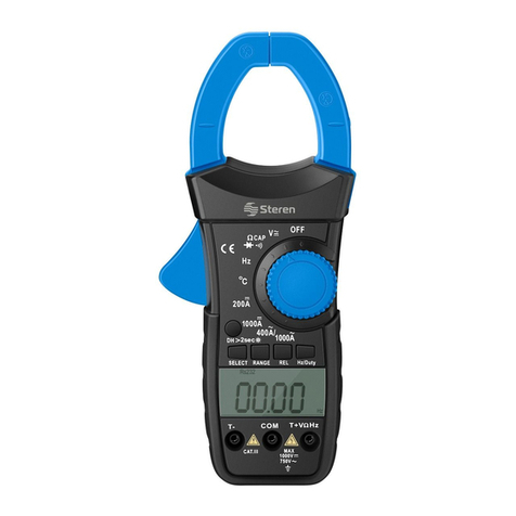
Steren MUL-400 User manual


ENGLISH
ENGLISH-2
Before using your new Professional Digital Multimeter,
please read this instruction manual to prevent any damage.
Put it away in a safe place for future references.
SECURITY INFORMATION
This multimeter has been designed according to IEC-1010
specifications for electronic testing equipment
Protection against electrical current damages
The testing points accomplish with security standards, if you
need to replace them, be sure that it match with the same
specifications or with the same model.
Never exceed the indicated limits in each measuring range.
When the multimeter forms a bridge with the circuit that is to
be measured, do not touch the points that are being used to
measure.
When you don’t know the range of the equipment to be
measured, set the dial to the highest range possible.
Before adjusting the dial to a different range or a different
function, disconnect the testing points from the multimeter.
Never measure resistance, capacity, inductance, diode, or
continuity on live circuits.
Whenever measuring voltages above 60 VDC or 30 VAC
rms, place your fingers above the protection rings on the
testing points.
Never connect the testing points from the multimeter to a
voltage source when the dial is on Amps, resistance,
capacity, inductance, temperature, frequency, diode,
transistor, or continuity mode.
MAINTENANCE
1.- Before opening your multimeter, always disconnect the
testing points from the multimeter’s source of electrical current.
2.- For an effective protection against fire, always replace a fuse
with one that has the same characteristics in voltage and current:
F 200 mA / 250V (fast fusion, <2ohms resistance), F 10 A / 250v
(fast fusion).
3.- If you notice any kind of malfunction or abnormality, stop all
use of your multimeter until it is checked by authorized
personnel.
4.- Never use your multimeter if the protective cover is not
properly placed.
5.- Never use your multimeter in explosive areas or situations.
•
•
•
•
•
•
•
•
•
Before usin
g
y
our new Professional Di
g
ital Multimeter,
p
lease read this instruction manual to prevent an
y
dama
g
e.
P
ut it awa
y
in a safe place for future references
.

ENGLISH
ENGLISH-3
6.- Do not store your multimeter in humid areas or anywhere it
will be exposed to direct sunlight.
7.- If the multimeter is going to be stored without use for an
extended period of time, remove the batteries in order to prevent
damage to your multimeter.
8.- To clean the multimeter use a humid rag and soft soap, do
not use abrasive products or solvents.
DESCRIPTION
1.- This multimeter is a portable, professional, digital instrument.
2.- 4 digit LCD screen, 25 mm tall, with polarity indicator, low
battery indicator and hold button.
3.- Identification
1) LCD screen
2) L/C button, use it to measuring inductance and capacitance.
3) On / Off button
4) Range dial, it is used to select the desired range
5) Board
6) Battery compartment
7) 10A connector
8) , Ω, °C, Δ, V, Hz, H connector
9) Common connector
10) DC / AC button. Press this button to select between DC or
AC voltage.
11) Light
12) Hold

ENGLISH
ENGLISH-4
GENERAL SPECIFICATIONS
ACCURACY
This unit is specified for a one year period in 64ºF to 82 º F
temperatures and 75% relative humidity.
Precision: This unit is specified for a one year period in 64ºF to
82 º F temperatures and 75% relative humidity.
Measurement method: High-scale integrated circuit with
double-integration A/D converter.
Sample rate: 0,4 seconds approx.
Screen: 25mm LCD
Maximum displayed value: 1999 (3,5 digits)
Overcharge indicator: “1”
Polarity indicator: “_”
Low battery indicator: battery
Operation altitude: 7000ft
Operation temperature: 32°F a 104°F
Storing temperature: 14°F a 122°F
Input: 9 V battery (1 x 9 V) alkaline or carbon-zinc
Maximum voltage between terminals and ground: 1000 VCD or
VCA
Dimensions: 185 x 84 x 38 mm
Weight: 441g including battery and case
DC VOLTAGE
Input impedance: 10Mohm
Protection against overcharge: 200mV range: 250Vcc or rms AC,
ranges from 2 to 700Vac: 1000 Vcc or 700Vac rms
Maximum votage input: 1000Vcc
In the range of small voltages, the meter can give unstable
readings when the points still don’t reach the circuit, this
process is normal, because the meter it’s very sensitive.
When the points touch the circuit, the meter will shows the
real reading.
I
n the ran
g
e of small volta
g
es, the meter can
g
ive unstable
readin
g
s when the points still don’t reach the circuit, this
p
rocess
i
s norma
l
,
b
ecause t
h
e meter
i
t’s ver
y
sens
i
t
i
ve.
W
hen the
p
oints touch the circuit, the meter will shows the
real readin
g.

AC VOLTAGE
Input impedance: 10Mohm
Protection against overcharge: 200mV range: 250Vcc or rms AC,
ranges from 2 to 700Vac: 1000 Vcc or 700Vac rms
Frequency range: 40 top 400MHz
Response: Average calculated in rms sine wave
Maximum voltage input: 700Vac rms
In the range of small voltages, the meter can give unstable
readings when the points still don’t reach the circuit, this
process is normal, because the meter it’s very sensitive.
When the points touch the circuit, the meter will shows the
real reading.
DC CURRENT
Protection against overcharge: Ranges from 2 to 200mA: F1:
200mA fuse 200mA / 250Vcc (fast fusion, <2ohm resistance) 10A
range: F2: 10 A / 250V fuse (fast fusion).
Maximum current input: mA connector: 200mA, 10 A connector:
10A
Voltage loss: 200mA
AC CURRENT
ENGLISH
ENGLISH-5
I
n the ran
g
e of small volta
g
es, the meter can
g
ive unstable
rea
di
n
g
s w
h
en t
h
e po
i
nts st
ill
d
on’t reac
h
t
h
e c
i
rcu
i
t, t
hi
s
p
rocess is normal, because the meter it’s ver
y
sensitive.
Wh
en t
h
e
p
o
i
nts touc
h
t
h
e c
i
rcu
i
t, t
h
e meter w
ill
s
h
ows t
h
e
rea
l
rea
di
n
g.

Protection against overcharge: Ranges from 2 to 200mA: F1:
200mA fuse 200mA / 250V (fast fusion, 2ohm resistance) 10A
range: F2: 10 A / 250V fuse (fast fusion).
Maximum current input: mA connector: 200mA, 10 A connector:
10A
Voltage loss: 200mA
Frequency range: 40 to 400Hz
Response: Average response, calculated in rms sine wave
RESISTANCE (ohm)
Maximum voltage in open circuit: 700mV
Protection against overcharge: 250 VDC or VAC rms in all
ranges.
CAPACITANCE
Protection against overcharge: F1: 200mA / 250V (fast fusion,
<2ohm resistance).
10A range: F2: 10A / 250V fuse (fast fusion).
INDUCTANCE
ENGLISH
ENGLISH-6

Protection against overcharge: F1: 200mA / 250V fuse (fast fu-
sion, <2ohm resistance), 10A range: F2: 10A / 250V fuse (fast
fusion).
Inductance test: Q10, 1kOhm internal impedance
TEMPERATURE
Protection against overcharge: F1: 200mA / 250V fuse (fast
fusion, <2ohm resistance).
FREQUENCY
Sensitivity: 200mV rms and 10V rms maximum input
Protection against overcharge: 250V rms
TRANSISTOR TEST
Current base: approximate 10 uA, Vce; approximate 2,8V
Protection against overcharge: F1: 200mA / 250V fuse (fast
fusion, <2ohm resistance).
DIODE TEST
Current test in direct direction: 1mA approx.
Current test in inverse direction: 2,8V approx.
Protection against overcharge: 250V or V ~ rms
ENGLISH
ENGLISH-7

AUDIBLE CONTINUITY TEST
Open circuit voltage: 2,8V approx.
Protection against overcharge: 250 V o V ~ rms
TTL LOGICAL LEVEL
When the logical level is under or above 0,8V, the LCD will
display “ “ and the buzzer emits a sound. When the logical level
is higher than or over 2,0V, the screen will display “ “.
OPERATION INSTRUCTIONS
HOLD
If you need to freeze the data value in the screen, press Hold. To
continue with the normal reading, press Hold once again.
BACK LIGHT
Press Light button if you need to illuminate the screen, after
pressed, the light will be on for 5 seconds.
The use of the Led consumes some energy because of the
big screen, if you use the light frequently, the battery will
discharged quickly; we recommend to use the light only in
specific cases.
The back light will be on for 5 seconds, after that will turn
off automatically.
When the voltage of the battery is less than 7V, the
low-battery icon displays in the screen.
DC / AC Switch
Press this button to convert the measured voltage to AC.
ENGLISH
ENGLISH-8
T
he use of the Led consumes some ener
gy
because of the
bi
g
screen, if
y
ou use the li
g
ht frequentl
y
, the batter
y
will
d
ischar
g
ed quickl
y
; we recommend to use the li
g
ht onl
y
in
sp
ecific cases.
T
he back li
g
ht will be on for 5 seconds, after that will turn
o
ff automaticall
y.
W
hen the volta
g
e of the batter
y
is less than 7V, the
l
ow-batter
y
icon displa
y
s in the screen
.

Excepting the AC voltage range and AC current, you must
release the DC / AC button.
L/C Switch
Press L/C button to measure capacitance and inductance.
MEASURING DC VOLTAGE
Warning
You cannot measure a voltage over 1000VDC, if you performs
this action, the meter’s internal circuit will be damaged.
1.- Connect the red testing point to the jack signaled “V” and the
black testing point to the jack signaled “COM”.
2.- Set the dial to the VDC / VAC setting
3.- Connect the testing points to the equipment to be measured.
4.- Turn the equipment to be measured on, the voltage will
appear on the LCD screen. The polarity will also appear.
5.- When the value to be measured is unknown, set the dial to
the maximum setting.
When a number “1” is displayed in the screen, it indicates
that exists an over range, please select a higher range.
MEASURING AC VOLTAGE
Warning
You cannot measure a voltage over 700VAC, if you performs this
action, the meter’s internal circuit will be damaged.
1.- Connect the red testing point to the jack signaled “V” and the
black testing point to the jack signaled “COM”.
2.- Set the dial to the VAC / VDC setting. Select the range.
3.- Press D / AC button to change to AC measure mode.
4.- Turn the equipment to be measured on, the voltage will
appear on the LCD screen.
5.- When the value to be measured is unknown, set the dial to
the maximum setting.
When a number “1” is displayed in the screen, it indicates
that exists an over range, please select a higher range.
E
xceptin
g
the AC volta
g
e ran
g
e and AC current,
y
ou must
release the DC / AC button
.
W
hen a number “1” is displa
y
ed in the screen, it indicates
t
hat exists an over ran
g
e, please select a hi
g
her ran
g
e
.
W
hen a number “1” is displa
y
ed in the screen, it indicates
t
hat exists an over ran
g
e, please select a hi
g
her ran
g
e
.
ENGLISH
ENGLISH-9

MEASURING DC / AC AMPS
Warning
1.- Connect the red testing point to the jack signaled “A” when
measuring up to 200 mA, and to the jack signaled “10A” when
measuring above and the black testing point to the jack signaled
“COM”.
2.- Set the dial to the mA or 10A setting. Then press DC / AC
button to choose the kind of amps to measure.
3.- Open the circuit and connect the testing points in serial with
the charge where the current must be measured.
4.- Read the current value in the screen. The polarity will be
displayed if we measure the direct current.
When a number “1” is displayed in the screen, it indicates
that exists an over range, please select a higher range.
MEASURING RESISTANCE
Warning
Make sure to disconnect the energy and fully discharge the
capacitors, before measure resistances.
1.- Connect the red testing point to the jack signaled “Ω” and the
black testing point to the jack signaled “COM”.
2.- Set the dial to Ohms (Ω) range.
3.- Connect the testing points to the circuit to be measured.
4.- The resistance value will appear on the LCD screen.
If the resistance to be measured is above 1 Mohm, the
multimeter will take a few seconds to stabilize the reading.
If the resistance exceeds the range, the LCD screen will
display “1”
MEASURING CAPACITANCE
Warning
To avoid an electrical shock, remove the testing points from the
circuit before to measure capacitances.
Make sure to fully discharge the capacitors before to put them
into the capacitor jack.
1.- Connect the capacitor jack to the meter.
2.- Set the dial to the “nF” range. Then press L/C.
3.- Before inserting the capacitor in the capacitor jack, make sure
that it has been completely discharged and make sure to respect
W
hen a number “1” is displa
y
ed in the screen, it indicates
t
hat exists an over ran
g
e, please select a hi
g
her ran
g
e
.
I
f the resistance to be measured is above 1 Mohm, the
m
ultimeter will take a few seconds to stabilize the readin
g.
I
f the resistance exceeds the ran
g
e, the LCD screen will
d
ispla
y
“1
”
ENGLISH
ENGLISH-10

polarity.
4.- The capacitor value will appear on the LCD screen.
MEASURING INDUCTANCE
1.- Connect the red testing point to the jack signaled “H” and the
black testing point to the jack signaled “COM”.
2.- Set the dial to H range. Then press L/C.
3.- Connect the testing points to the inductor to be measured.
4.- The inductor value will appear on the LCD screen.
Be sure to remove the coil from any magnetic field, in order
to obtain an accurate measure.
MEASURING TEMPERATURE
Warning
Do not connect the thermo pair to energized circuit, in order to
avoid electrical shock.
1.- Set the dial to °C range.
2.- The room temperature will appears in the screen.
3.- Insert the thermo pair type “K” inside of the “COM” jack and
“°C”, then make contact with the object to be measured with the
tip of the thermo-pair.
4.- The temperature value will appear on the LCD screen.
MEASURING FREQUENCY
1.- Connect the red testing point to the jack signaled “Hz” and
the black testing point to the jack signaled “COM”.
2.- Set the dial to 20KHz range.
3.- Connect the testing points to the circuit to be measured.
4.- The frequency value will appear on the LCD screen.
The reading it’s only available using voltages higher than
10Vrms, but the accuracy is not guaranteed.
In noisy environments, it is preferable use cable for small
signals.
MEASURING DIODES
1.- Connect the red testing point to the jack signaled “V” and the
black testing point to the jack signaled “COM”.
2.- Set the dial to range.
3.- Connect the red testing point to the anode and the black
Be sure to remove the coil from an
y
ma
g
netic field, in order
t
o obtain an accurate measure
.
T
he readin
g
it’s onl
y
available usin
g
volta
g
es hi
g
her than
1
0Vrms, but the accurac
y
is not
g
uaranteed.
I
n nois
y
environments, it is preferable use cable for small
s
i
g
nals
.
ENGLISH
ENGLISH-11

testing point to the cathode.
4.- The voltage value will appear on the LCD screen, in mVolts.
The meter will shows the dropped voltage in approximate
straight direction from the diode.
If the testing points are inverted, the meter will shows “1”
When a testing points is not connected, the meter will
display “1”.
MEASURING AUDIBLE CONTINUITY
Warning
Make sure to discharge the capacitors and remove any kind of
energy, before to test continuity.
1.- Connect the red testing point in the jack signaled “Ω” and the
black testing point in the jack signaled “COM”.
2.- Set the dial to the “)))” range.
3.- Connect the testing points on the circuit to be measured. If
the resistance is less than 50 Ohms the multimeter will sound.
If the circuit is open, the screen will display “1”.
TRANSISTOR MEASUREMENT –hFE-
1.- Set the dial to the hFE range.
2.- Determine if the transistor is NPN or PNP and localize the
emitter, base, and collector. Connect the testing points in the
jacks for transistor testing.
3.- The multimeter will show the approximate hFE value.
TTL LOGICAL TEST
1.- Connect the red testing point in the jack signaled “V” and the
black testing point in the jack signaled “COM”.
2.- Set the dial to the “ ” range.
3.- Connect the testing points on the circuit to be measured
4.- When the logical level is less than 0,8V the screen will display
“ “ and the meter will sound. When the logical level is over
than 2V, the screen will display “ “.
MAINTENANCE
BATTERY REPLACEMENT
Warning
Before removing the cover from your multimeter, make sure the
Th
e meter w
ill
s
h
ows t
h
e
d
roppe
d
vo
l
ta
g
e
i
n approx
i
mate
s
trai
g
ht direction from the diode
.
I
f the testin
g
points are inverted, the meter will shows “1
”
Wh
en a test
i
n
g
po
i
nts
i
s not connecte
d
, t
h
e meter w
ill
d
ispla
y
“1”
.
ENGLISH
ENGLISH-12
I
f the circuit is open, the screen will displa
y
“1”
.

testing points are disconnected to avoid the risk of electrical
shock.
1.- If the battery icon displays in the screen, you must replace
the battery.
2.- Remove the back cover.
3.- Replace the battery with a new one.
4.- Replace the battery cover.
FUSE REPLACEMENT
Warning
Before removing the cover from your multimeter, make sure the
testing points are disconnected to avoid the risk of electrical
shock.
If these need to be replaced make sure to use a fuse of the same
model and with the same characteristics (F1: F 200 mA / 250 V
fast response, <2 Ohms, F2: F 10 A / 250V fast response).
1.- The fuse rarely needs to be replaced and when it does, it is
usually due to an error in operation.
2.- To replace the fuse, remove the cover from the multimeter
removing the three screws on the back of the multimeter.
REPLACING THE TESTING POINTS
Warning
The complete satisfaction of accurate readings can only be
guaranteed using the included testing points. If these need to be
replaced make sure to use testing points of the same model and
with the same characteristics (1 000V 10A).
ACCESSORIES
User’s manual
Testing points
Battery (included)
Thermo-pair type “K”
Case
Multifunctional connector
The characteristics for this multimeter are subject to change
without notice.
•
•
•
•
•
•
T
he characteristics for this multimeter are sub
j
ect to chan
g
e
wi
t
h
out not
i
ce
.
ENGLISH
ENGLISH-13


ESPAÑOL
Antes de utilizar su nuevo multímetro Profesional Digital lea
este instructivo para evitar cualquier mal funcionamiento.
Guárdelo para futuras referencias.
INFORMACION DE SEGURIDAD
Este multímetro ha sido diseñado de acuerdo con la Norma
IEC-1010 aplicable a instrumentos electrónicos de medición.
Cuando use su multímetro, debe Ud. observar las siguientes
reglas de seguridad:
Protección contra daños por corriente eléctrica
Las puntas de prueba cumplen con estándares de
seguridad, si necesita reemplazarlas que sea con unas de
las mismas
características o mismo modelo.
Nunca exceda los límites de valor indicados en cada rango
de medición.
Cuando el multímetro forma un puente con el circuito a
medir no toque las terminales de puntas de prueba.
Cuando el valor de la escala a medir es desconocido,
coloque el selector de rango en la posición más alta.
Antes de girar el selector de rango a diferente escala o
función, desconecte las puntas de prueba del circuito.
Cuando lleve hacia fuera la medición o interrumpa los
circuitos de poder, siempre recuerde que los pulsos de
amplitud de voltaje pueden ser muy altos, lo cual puede
dañar el multímetro.
Nunca mida resistencia, capacitancia, inductancia, diodo y
continuidad en circuitos vivos (alimentados).
Siempre que mida voltajes arriba de 60 VCD o 30 VCA rms,
ponga los dedos por encima de los anillos de
protección (barril) de las puntas de prueba.
Nunca conecte las puntas del medidor a una fuente de
voltaje mientras el interruptor de funciones se encuentre en
amperes, resistencia, capacitancia, inductancia,
temperatura, frecuencia, diodo, transistor o modo de
continuidad.
MANTENIMIENTO
1. Antes de abrir el multímetro, siempre desconecte las puntas
de prueba de las fuentes de corriente eléctrica.
2. Para una protección efectiva contra fuego, siempre reemplace
•
•
•
•
•
•
•
•
•
•
•
ESPAÑOL-2
A
ntes de utilizar su nuevo multímetro Profesional Di
g
ital lea
e
ste instructivo para evitar cualquier mal funcionamiento.
G
uárdelo
p
ara futuras referencias
.

ESPAÑOL
ESPAÑOL-3
el fusible por uno de las mismas especificaciones en voltaje y
corriente : F 200 mA / 250V (fusión rápida, resistencia <2 Ohms)
F 10 A / 250 V (fusión rápida).
3. Si nota cualquier falla o anormalidad, el multímetro no debe
usarse hasta no ser revisado por personal autorizado.
4. Nunca use el medidor si la cubierta protectora no esta puesta
adecuadamente en su lugar.
5. Nunca use el multímetro bajo condiciones en áreas explosi-
vas.
6. No lo almacene en lugares húmedos ni lo exponga
directamente a los rayos del sol.
7. Si el multímetro va ser almacenado por largo tiempo, remueva
las baterías para prevenir cualquier daño a la unidad.
8. Para limpiar el multímetro utilice una trapo húmedo y
detergente suave, no utilice abrasivos y/o solventes.
DESCRIPCION
1- El multímetro es un instrumento Digital Profesional portátil.
2- Pantalla de 4 dígitos LCD, 25 mm de altura, con indicador
de polaridad, indicador de batería baja y botón de retención de
datos.
3- Identificación
1) Pantalla de cristal líquido (LCD display)
2) Botón L/C (Inductancia /capacitancia), se utiliza para medir
inductancia o capacitancia.
3) Botón de encendido
4) Interruptor de rango, es utilizado para seleccionar le rango
deseado
5) Tablero
6) Compartimiento de batería
7) Conector de 10 A
8) Conector de , Ω, °C, Δ, V, Hz, H.
9) Conector común
10) Botón de DC/AC (corriente alterna /corriente directa) Este
botón se utiliza para seleccionar el
voltaje de CD o CA
11) Botón de Luz
12) Botón de HOLD (retención de datos)

ESPAÑOL
ESPECIFICACIONES GENERALES
Precisión:
Esta especificada para un período de un año en condiciones de
18°C a 28°C (64°F a 82°F) con humeada relativa de 75%
Método de medición: Convertidor de A/D con Integración de
doble Inclinación.
Tiempo de muestreo: 0,4 segundos aproximadamente.
Pantalla de: 25 mm de cristal liquido (LCD)
Máximo valor mostrado: 1999 (3,5 dígitos)
Indicación de sobre rango: “1”
Indicación de polaridad: “—“
Indicador de batería baja.
Altitud e Operación: 2000 m (7000 ft)
Temperatura de operación: 0 a 40°C (32°F a 104°F)
ESPAÑOL-4

Temperatura de almacenaje: -10°C a 50°C (14°F a 122°F)
Alimentación: Batería de 9 V alcalina o carbón zinc. (1 x 9 V )
Voltaje máximo entre terminales y tierra: 1000 VCD o VCA
Dimensiones: 185 x 84 x 38 mm
Peso: 441 g incluye batería y funda.
VOLTAJE DE CD
Impedancia de entrada de 10Mohm.
Protección contra sobrecarga: Rango de 200 mV : 250 Vcc o
rms ca, Rangos de 2 a 700 Vca: 1000
Vcc o 700 Vca rms
Máxima entrada de voltaje: 1000 Vcc
En el rango de pequeños voltajes el medidor puede
presentar inestabilidad en la lectura cuando las puntas no
han alcanzado el circuito, esto es normal porque el medidor
es muy sensitivo. Cuando las puntas toquen el circuito el
medidor mostrará la lectura verdadera.
VOLTAJE DE CA
Impedancia de entrada de 10 Mohms
Protección contra sobrecarga: Rango de 200 mV : 250 Vcc o
rms ca, Rangos de 2 a 700 Vca: 1000
Vcc o 700 Vca rms
Rango de Frecuencia: 40 a 400 MHz
Respuesta: Promedio calibrado en onda senoidal rms
Máxima entrada de voltaje: 700 Vca rms
ESPAÑOL-5
ESPAÑOL
E
n el ran
g
o de pequeños volta
j
es el medidor puede
p
resentar inestabilidad en la lectura cuando las
p
untas no
h
an a
l
canza
d
o e
l
c
i
rcu
i
to, esto es norma
l
p
or
q
ue e
l
me
did
or
e
s mu
y
sensitivo. Cuando las puntas toquen el circuito el
m
edidor mostrará la lectura verdadera
.

En el rango de pequeños voltajes el medidor puede
presentar inestabilidad en la lectura cuando las puntas no
han alcanzado el circuito, esto es normal porque el medidor
es muy sensitivo. Cuando las puntas toquen el circuito el
medidor mostrará la lectura verdadera.
CORRIENTE DE CD
Protección contra sobrecarga: Rangos 2 a 200 mA: F1: fusible
de 200 mA / 250 V (fusión rápida,
resistencia <2 Ohms), Rango de 10 A : F2: fusible de 10 A / 250
V (fusión rápida).
Máxima entrada de corriente: Conector de mA: 200 mA,
conector de 10 A: 10 A
Caída de voltaje: 200mA
CORRIENTE DE CA
Protección contra sobrecarga: Rangos 2 a 200 mA: F1: fusible
de 200 mA / 250 V (fusión rápida, resistencia <2 Ohms), Rango
de 10 A : F2: fusible de 10 A/250 V (fusión rápida).
Máxima entrada de corriente: Conector de mA: 200 mA,
conector de 10 A: 10 A
Caída de voltaje: 200 mA
Rango de Frecuencia: 40 a 400 Hz
Respuesta: Respuesta promedio, calibrado en rms de onda
senoidal
ESPAÑOL
ESPAÑOL-6
E
n e
l
ran
g
o
d
e pequeños vo
l
ta
j
es e
l
me
did
or pue
d
e
p
resentar inestabilidad en la lectura cuando las
p
untas no
han alcanzado el circuito, esto es normal
p
or
q
ue el medidor
e
s mu
y
sensitivo. Cuando las puntas toquen el circuito el
m
edidor mostrará la lectura verdadera
.

RESISTENCIA (Ohms)
Voltaje aproximado en circuito abierto: 700mV
Protección contra sobrecarga: 250 VCD o VCA rms
CAPACITANCIA
Protección contra sobrecarga: F1: fusible de 200 mA / 250 V
(fusión rápida, resistencia <2 Ohms),
Rango de 10 A : F2: fusible de 10 A / 250 V (fusión rápida).
INDUCTANCIA
Protección contra sobrecarga: F1: fusible de 200 mA / 250 V
(fusión rápida, resistencia <2 Ohms)
Prueba de Inductancia : Q >10, impedancia interna de <1 kOhm
TEMPERATURA
ESPAÑOL
ESPAÑOL-7
Table of contents
Languages:
Other Steren Multimeter manuals

Steren
Steren MUL-005 User manual

Steren
Steren MUL-605 User manual

Steren
Steren MUL-100 User manual

Steren
Steren MUL-300 User manual

Steren
Steren MUL-050 User manual

Steren
Steren MUL-282 User manual

Steren
Steren MUL-115 User manual

Steren
Steren MUL-055 User manual

Steren
Steren MUL-650 User manual

Steren
Steren MUL-030 User manual

Steren
Steren MUL-010 User manual

Steren
Steren MUL-100 User manual

Steren
Steren MUL-035 User manual

Steren
Steren MUL-015 User manual

Steren
Steren MUL-283 User manual

Steren
Steren MUL-052 User manual

Steren
Steren MUL-050 User manual

Steren
Steren MUL-010 User manual

Steren
Steren MUL-095 User manual
Steren
Steren MUL-005 User manual