xiii
List of Figures and Tables Operator Manual P129394-020
LIST OF FIGURES
Descrption Page
Figure 4-1. Vented Closures ..............................................................................................................................4-5
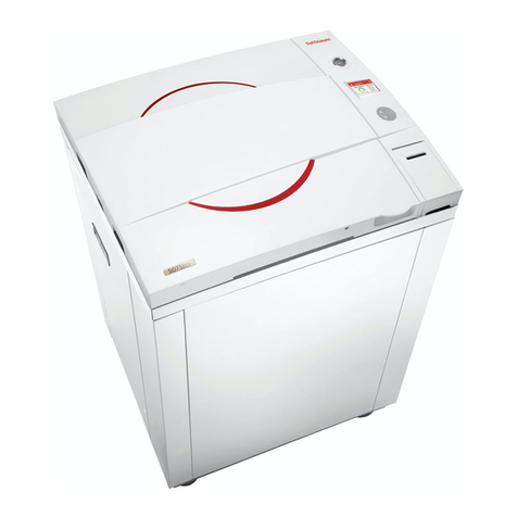
Figure 5-1. AMSCO 400 Series Small Steam Sterilizer ......................................................................................5-1
Figure 5-2. Basic Controls..................................................................................................................................5-3
Figure 5-3. Optional Steam Generator Valve Controls (Sterilizer Frame Not Shown for Clarity)........................5-4
Figure 5-4. Typical Out-Of-Cycle and In-Cycle Displays...................................................................................5-5
Figure 5-5. Alarm Display Examples..................................................................................................................5-6
Figure 5-6. Control Panels..................................................................................................................................5-8
Figure 5-7. Cycle Selection Touchpads...........................................................................................................5-10
Figure 5-8. Values Touch-Screen Pads ...........................................................................................................5-11
Figure 5-9. Cycle Abort Touch-Screen Pad .....................................................................................................5-12
Figure 5-10. Printer Features (Printer Door Open) .............................................................................................5-13
Figure 5-11. Typical Printout ..............................................................................................................................5-15
Figure 5-12. Power Door Floor Pedal .................................................................................................................5-16
Figure 5-13. Emergency Door Opening Procedure ...........................................................................................5-17
Figure 5-14. Emergency Stop Switch, Key and Guard ......................................................................................5-18
Figure 5-15. Press Abort Button to End Cycles When Needed .........................................................................5-18
Figure 5-16. Emergency Stop Label ..................................................................................................................5-19
Figure 5-17. Integral Generator Flush Cycle......................................................................................................5-22
Figure 6-1. Utility Supply Valves and Basic Sterilizer Controls ..........................................................................6-2
Figure 6-2. Optional Steam Generator Check List .............................................................................................6-3
Figure 6-3. Align Loading Car with Chamber Opening .....................................................................................6-6
Figure 6-4. Sterilizer Chamber Equipped with Rack and Shelves .....................................................................6-8
Figure 6-5. Prevac Cycle In-Cycle Screens .....................................................................................................6-10
Figure 6-6. Typical Prevacuum Cycle Printouts ...............................................................................................6-12
Figure 6-7. Gravity Cycle In-Cycle Screens.....................................................................................................6-14
Figure 6-8. Typical Gravity Cycle Printout........................................................................................................6-16
Figure 6-9. Liquid Cycle In-Cycle Screens ......................................................................................................6-18
Figure 6-10. Typical Printout of a Liquid Cycle ..................................................................................................6-20
Figure 6-11. SFPP Cycle In-Cycle Screens........................................................................................................6-22
Figure 6-12. Typical Printouts – 270°F SFPP and 275°F SFPP Cycles ..............................................................6-24
Figure 6-13. Test Cycles Start-Cycle Screens ...................................................................................................6-25
Figure 6-14. Daily Air Removal (Bowie-Dick) Test Cycle Printout......................................................................6-28
Figure 6-15. Typical Printout of a Leak Test Cycle ............................................................................................6-30
Figure 6-16. Cycle Graph – 270°F or 275°F Prevacuum and Air Removal (Bowie-Dick) Cycles......................6-32
Figure 6-17. Cycle Graph – Gravity Cycle .........................................................................................................6-33
Figure 6-18. Cycle Graph – Leak Test ...............................................................................................................6-33
Figure 6-19. Cycle Graph – Steam Flush Pressure Pulse (SFPP) Cycles ..........................................................6-34
Figure 6-20. Cycle Graph – Liquid Cycle...........................................................................................................6-34
Figure 7-1. Accessing Change Cycle Values, Part 1 of 3..................................................................................7-5


