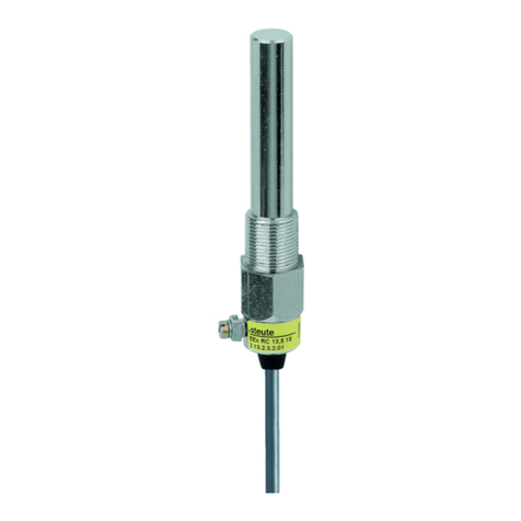
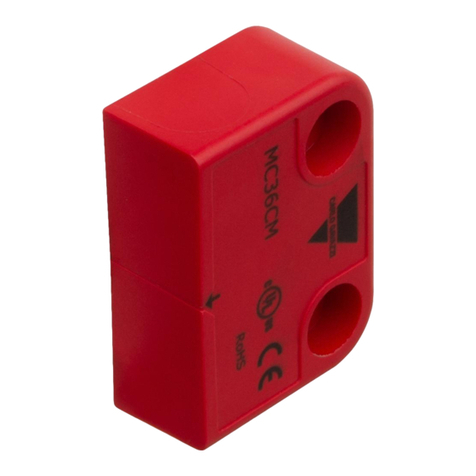
steute RC 3G/D Series Programming manual

//
Ex RC … -3G/D
steute Technologies GmbH & Co. KG,
Brückenstraße 91, 32584 Löhne, Germany, www.steute.com
1 / 16
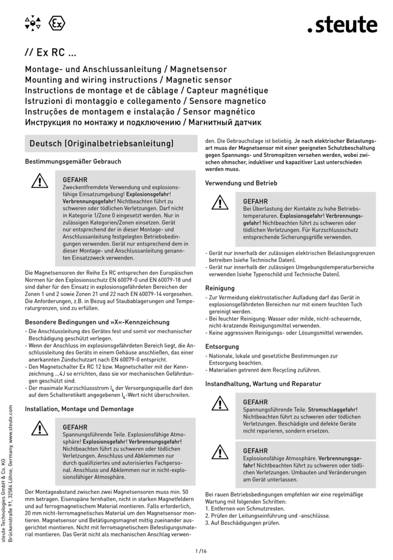
Montage- und Anschlussanleitung / Magnetsensor
Mounting and wiring instructions / Magnetic sensor
Instructions de montage et de câblage / Capteur magnétique
Istruzioni di montaggio e collegamento / Sensore magnetico
Instruções de montagem e instalação / Sensor magnético
Инструкция по монтажу и подключению / Магнитный датчик
Nutzung der Montage- und Anschlussanleitung
Zielgruppe: autorisiertes Fachpersonal.
Sämtliche in dieser Montageanleitung beschriebenen Handhabungen
dürfen nur durch ausgebildetes und vom Anlagenbetreiber autorisier-
tes Fachpersonal durchgeführt werden.
1. Montage- und Anschlussanleitung lesen und verstehen.
2. Geltende Vorschriften über Arbeitssicherheit und Unfallverhütung
einhalten.
3. Gerät installieren und in Betrieb nehmen.
Auswahl und Einbau der Geräte sowie ihre steuerungstechnische Ein-
bindung sind an eine qualifizierte Kenntnis der einschlägigen Gesetze
und normativen Anforderungen durch den Maschinenhersteller
geknüpft.
Im Zweifelsfall ist die deutsche Sprachversion dieser
Anleitung maßgeblich.
Lieferumfang
1 Gerät, 1 Montage- und Anschlussanleitung, Kartonage.
Sicherheitshinweise
=In diesem Dokument wird das Warndreieck zu-
sammen mit einem Signalwort verwendet, um
auf gefährliche Situationen hinzuweisen.
Die Signalwörter haben folgende Bedeutungen:
HINWEIS
zeigt eine Situation an, die einen
Sachschaden zur Folge haben
könnte.
VORSICHT
zeigt eine Situation an, die eine
geringfügige oder mäßige Ver-
letzung zur Folge haben könnte.
WARNUNG
zeigt eine Situation an, die den
Tod oder eine schwere Verlet-
zung zur Folge haben könnte.
GEFAHR
zeigt eine Situation an, die eine
schwere Verletzung oder den
Tod zur Folge hat.
Bestimmungsgemäßer Gebrauch
=
GEFAHR
Zweckentfremdete Verwendung und explosions-
fähige Einsatzumgebung! Explosionsgefahr! Ver-
brennungsgefahr! Darf nicht in Kategorien 1 und 2/
Zonen 0 und 1 und Zonen 20 und 21 eingesetzt wer-
den. Nur in zulässigen Kategorien/Zonen einsetzen.
Nur entsprechend der in dieser Montageanleitung
festgelegten Betriebsbedingungen verwenden. Nur
entsprechend dem in dieser Montageanleitung ge-
nannten Einsatzzweck verwenden.
Die Magnetsensoren der Reihe Ex RC entsprechen den Europäischen
Normen für den Explosionsschutz EN 60079-0 und EN 60079-18. Sie
sind für den Einsatz in explosionsgefährdeten Bereichen der Zonen
2 und 22 nach EN 60079-14 vorgesehen. Die Anforderungen der
EN 60079-14, z.B. in Bezug auf Staubablagerungen und Temperatur-
grenzen, einhalten.
Besondere Bedingungen und »X«-Kennzeichnung
- Die Anschlussleitung des Gerätes fest und somit vor mechanischer
Beschädigung geschützt verlegen.
- Wenn der Anschluss im explosionsgefährdeten Bereich liegt, die An-
schlussleitung des Geräts in einem Gehäuse anschließen, das einer
anerkannten Zündschutzart nach EN 60079-0 entspricht.
- Den Magnetsensor Ex RC 12 bzw. Magnetsensor mit der Kennzeich-
nung ...4J so errichten, dass sie vor mechanischen Gefährdungen
geschützt sind.
- Der maximale Kurzschlussstrom Ikder Versorgungsquelle darf den
auf dem Schalteretikett angegebenen Ik-Wert nicht überschreiten.
Installation, Montage, Demontage
=
GEFAHR
Spannungsführende Teile. Explosionsfähige Atmo-
sphäre! Explosionsgefahr! Verbrennungsgefahr!
Anschluss und Abklemmen nur durch qualifiziertes
und autorisiertes Fachpersonal. Anschluss und Ab-
klemmen nur in nicht-explosionsfähiger
Umgebung.
Das Gerät auf einer ebenen Fläche befestigen. Das Gerät nicht als me-
chanischen Anschlag verwenden. Die Gebrauchslage ist beliebig. Der
Montageabstand zwischen zwei Magnetsensoren muss min. 50 mm
betragen. Eisenspäne fernhalten, nicht in starken Magnetfeldern und
auf ferrogmagnetischem Material montieren. Falls erforderlich,
20 mm nicht-ferromagnetisches Material um den Magnetsensor mon-
tieren. Magnetsensor und Betätigungsmagnet mittig zueinander aus-
gerichtet montieren. Nicht mit ferromagnetischem Befestigungsmate-
rial montieren. Je nach elektrischer Belastungsart muss der Magnet-
sensor mit einer geeigneten Schutzbeschaltung gegen Spannungs-
und Stromspitzen versehen werden, wobei zwischen ohmscher, in-
duktiver und kapazitiver Last unterschieden werden muss. Der Mag-
netsensor darf nicht in staubexplosionsgefährdeten Bereichen, in
dehnen mit Gleitstielbüschelentladungen zu rechnen ist, errichtet
werden.
Verwendung und Betrieb
=
GEFAHR
Bei Überlastung der Kontakte zu hohe Betriebs-
temperaturen. Explosionsgefahr! Verbrennungs-
gefahr! Für Kurzschlussschutz korrekte Siche-
rungsgröße beachten.
Deutsch (Originalbetriebsanleitung)

//
Ex RC … -3G/D
steute Technologies GmbH & Co. KG,
Brückenstraße 91, 32584 Löhne, Germany, www.steute.com
2 / 16
Montage- und Anschlussanleitung / Magnetsensor
Mounting and wiring instructions / Magnetic sensor
Instructions de montage et de câblage / Capteur magnétique
Istruzioni di montaggio e collegamento / Sensore magnetico
Instruções de montagem e instalação / Sensor magnético
Инструкция по монтажу и подключению / Магнитный датчик
Use of the mounting and wiring instructions
Target group: authorised and qualified staff.
All actions described in these instructions may only be performed by
qualified persons who have been trained and authorised by the
operating company.
1. Read and understand these mounting and wiring instructions.
2. Comply with the valid occupational safety and accident prevention
regulations.
3. Install and operate the device.
Selection and installation of devices and their integration in control
systems demand qualified knowledge of all the relevant laws, as well
as the normative requirements of the machine manufacturer.
In case of doubt, the German language version of these instructions
shall prevail.
Scope of delivery
1 device, 1 mounting and wiring instructions, carton.
Safety information
=In this document, the warning triangle is used
together with a signal word to indicate a
hazardous situation.
The signal words have the following meanings:
NOTICE
indicates a situation which may
result in material damage.
CAUTION
indicates a situation which may
result in minor or moderate
injury.
WARNING
indicates a situation which may
result in serious injury or death.
DANGER
indicates a situation which will
result in serious injury or death.
Intended use
=
DANGER
Misuse and explosive environment. Explosion
hazard! Risk of burns! Not for use in categories 1
and 2/zones 0 and 1 and zones 20 and 21. Use only
in permitted categories/zones. Use device only in
accordance with the operating conditions defined
in the mounting and wiring instructions. Use device
only in accordance with the intended purpose de-
fined in the mounting and wiring instructions.
The magnetic sensors in series Ex RC comply with the European
standards for explosion protection EN 60079-0 and EN 60079-18. They
are intended for use in explosive hazardous areas of zones 2 and 22
according to EN 60079-14. Comply with the requirements of EN 60079-
14, e.g. with regard to dust deposits and temperature limits.
- Gerät nur innerhalb der zulässigen elektrischen Belastungsgrenzen
betreiben (siehe Technische Daten).
- Gerät nur innerhalb der zulässigen Umgebungstemperaturbereiche
verwenden (siehe Typenschild und Technische Daten).
Reinigung
- Zur Vermeidung elektrostatischer Aufladung darf das Gerät in
explosionsgefährdeten Bereichen nur mit einem feuchten Tuch
gereinigt werden.
- Bei feuchter Reinigung: Wasser oder milde, nicht-scheuernde,
nicht-kratzende Reinigungsmittel verwenden.
- Keine aggressiven Reinigungs- oder Lösungsmittel verwenden.
Entsorgung
- Nationale, lokale und gesetzliche Bestimmungen zur
Entsorgung beachten.
- Materialien getrennt dem Recycling zuführen.
Instandhaltung, Wartung, Reparatur
=
GEFAHR
Spannungsführende Teile. Stromschlaggefahr!
Beschädigte und defekte Geräte nicht reparieren,
sondern ersetzen.
=
GEFAHR
Explosionsfähige Atmosphäre. Verbrennungs-
gefahr! Umbauten und Veränderungen am Gerät
unterlassen.
Bei rauen Betriebsbedingungen empfehlen wir eine regelmäßige
Wartung mit folgenden Schritten:
1. Entfernen von Schmutzresten.
2. Prüfen der Leitungseinführung und -anschlüsse.
Hinweise
Der elektrische Anschluss darf nur von autorisiertem Fachpersonal
durchgeführt werden. Umbauten und Veränderungen am Gerät, die
den Explosionsschutz beeinträchtigen, sind nicht gestattet. Für das
Errichten von elektrischen Betriebsmitteln in explosionsgefährdeten
Bereichen gilt die EN 60079-14. Zu beachten sind zudem die ATEX-
Prüfbescheinigung und die darin enthaltenen besonderen Bedingun-
gen. Es liegt im Verantwortungsbereich des Herstellers einer Anlage
oder Maschine, die korrekte Gesamtfunktion sicherzustellen. Techni-
sche Änderungen vorbehalten. steute übernimmt keine Haftung für
Empfehlungen, die durch diese Beschreibung gegeben oder impliziert
werden. Aufgrund dieser Beschreibung können keine neuen, über die
allgemeinen steute-Lieferbedingungen hinausgehenden, Garantie-,
Gewährleistungs- oder Haftungsansprüche abgeleitet werden.
Deutsch (Originalbetriebsanleitung) English

//
Ex RC … -3G/D
steute Technologies GmbH & Co. KG,
Brückenstraße 91, 32584 Löhne, Germany, www.steute.com
3 / 16
Montage- und Anschlussanleitung / Magnetsensor
Mounting and wiring instructions / Magnetic sensor
Instructions de montage et de câblage / Capteur magnétique
Istruzioni di montaggio e collegamento / Sensore magnetico
Instruções de montagem e instalação / Sensor magnético
Инструкция по монтажу и подключению / Магнитный датчик
English Disposal
- Observe national, local and legal regulations concerning disposal.
- Recycle each material separately.
Service, maintenance, repair
=
DANGER
Live parts. Electric shock hazard! Do not repair de-
fective or damaged devices. Replace them.
=
DANGER
Explosive atmosphere. Risk of burns! Do not re-
build or modify the device in any way.
With rough conditions, we recommend routine maintenance as follows:
1. Removal of all dirt particles.
2. Check sealing of the cable or conduit connections.
N.B.
The electrical connection may only be carried out by authorised per-
sonnel. Reconstruction and alterations to the device which might af-
fect the explosion protection are not allowed. Furthermore, EN 60079-
14 has to be applied for the installation of electrical equipment in ex-
plosive hazardous areas. Moreover, the ATEX test certificate and the
special conditions therein have to be observed. It is the responsibility
of the manufacturer of a plant or machine to guarantee the correct
general function. Subject to technical modifications. steute does not
assume any liability for recommendations made or implied by this de-
scription. New claims for guarantee, warranty or liability cannot be de-
rived from this document beyond the general terms and conditions
of delivery.
Français
Utilisation des instructions de montage et de câblage
Groupe cible: personnel autorisé et compétent.
Toutes les manipulations décrites dans cette notice d‘installation ne
doivent être effectuées que par du personnel formé et autorisé par la
société exploitante.
1. Lire et comprendre les instructions de montage et de câblage.
2. Respecter les règles de sécurité et de prévention des accidents en
vigueur.
3. Installer l’appareil et le mettre en service.
La sélection et l'installation des appareils et leurs intégrations dans
les systèmes de commande exigent une connaissance approfondie
de toutes les lois pertinentes, ainsi que des exigences normatives du
fabricant de la machine.
En cas de doute, la version allemande fait référence.
Volume de livraison
1 appareil, 1 instruction de montage et de câblage, carton.
Special conditions and »X« marking
- Lay the cable securely to protect it from mechanical damage.
- If the connection is carried out within an explosive hazardous areas,
connect the cable inside an enclosure which meets the requirements
of an approved ignition protection type per EN 60079-0.
- Install the magnetic sensor Ex RC 12 and magnetic sensors with a
»4J« marking in such a way as to protect them from
mechanical damage.
- The maximum short circuit current Ikof the supply source may not
exceed the Ik value given on the product label.
Installation, mounting, dismantling
=
DANGER
Live parts. Explosive atmosphere. Explosion haz-
ard! Risk of burns! Connecting and disconnecting
only to be performed by qualified and authorised
personnel. Connecting and disconnecting only in
non-explosive environment.
Mount the device on an even surface.
Do not use the device as a me-
chanical endstop. Any mounting position is possible. The mounting
distance between two magnetic sensors must be min. 50 mm. Keep
away ferromagnetic cuttings, do not mount in strong magnetic fields
and on ferromagnetic materials. If necessary, mount 20 mm of
non-ferromagnetic material around the magnetic sensor. Mount mag-
netic sensor and actuating magnet so that they centrically align with
each other. Do not fix with ferromagnetic mounting material. Depend-
ing on the electrical load the magnetic sensor must be protected from
voltage and current peaks by suitable protection circuits. It is re-
quired to distinguish between ohmic, inductive and capacitive load.
The magnetic sensor must not be installed within dust-explosive en-
dangered areas where propagating brush discharge can occur.
Application and operation
=DANGER
In case of overloaded contacts too high operation
temperatures. Explosion hazard! Risk of burns! For
short-circuit protection observe correct fuse size.
- Use device only within the permitted electrical load limits (see
technical data).
- Use device only within the permitted ambient temperature range
(see product label and technical data).
Cleaning
- Use a damp cloth to clean devices in explosive hazardous areas. This
prevents electrostatic charge.
- In case of damp cleaning: use water or mild, non-scratching,
non-chafing cleaners.
- Do not use aggressive cleaners or solvents.

//
Ex RC … -3G/D
steute Technologies GmbH & Co. KG,
Brückenstraße 91, 32584 Löhne, Germany, www.steute.com
4 / 16
Montage- und Anschlussanleitung / Magnetsensor
Mounting and wiring instructions / Magnetic sensor
Instructions de montage et de câblage / Capteur magnétique
Istruzioni di montaggio e collegamento / Sensore magnetico
Instruções de montagem e instalação / Sensor magnético
Инструкция по монтажу и подключению / Магнитный датчик
Français
Instructions de sécurité
=Dans ce document, le triangle de présignalisa-
tion est utilisé avec un mot-clé pour signaler
les situations dangereuses.
Les mots-clés ont les significations suivantes:
NOTICE
indique une situation qui pour-
rait entraîner un dommage
matériel.
ATTENTION
indique une situation qui pour-
rait entraîner une blessure
légère ou gravité modérée.
MISE EN GARDE
indique une situation qui pour-
rait entraîner la mort ou une
blessure grave.
DANGER
indique une situation qui en-
traîne une blessure grave ou
la mort.
Utilisation conforme
=
DANGER
D’utilisations non conformes et un environnement
potentiellement explosif. Risque d'explosion!
Risque de brûlure! Ne doit pas être utilisé dans
la catégories 1 et 2/zones 0 et 1 et zones 20 et 21.
Utiliser uniquement dans les catégories/zones au-
torisées. N’utiliser l'appareil qu’en conformité avec
les conditions de fonctionnement stipulées dans
ces instructions de montage et de câblage. Utiliser
uniquement en conformité avec les applications sti-
pulées dans ces instructions de montage et
de câblage.
Les capteurs magnétiques de la série Ex RC sont conformes aux
normes Européennes pour la protection contre les explosions EN
60079-0 et EN 60079-18. Ils sont prévus pour l'utilisation en environ-
nements à risque d'explosion des zones 2 et 22 selon EN 60079-14.
Observer les exigences de EN 60079-14, par ex. en rapport avec les
dépôts de poussières et limites de températures.
Conditions particulières et marquage »X«
- Poser et fixer le câble de raccordement de l'appareil de manière à
le protéger contre tout dommage mécanique.
- Brancher le câble de raccordement de l'appareil dans un boîtier
qui répond aux exigences d'un mode de protection reconnu selon
EN 60079-0, si le raccordement se trouve dans un environnement
à risque d'explosion.
- Installer le capteur magnétique Ex RC 12 ou le capteur magnétique
avec le marquage ...4J de manière à le protéger contre tous
risques mécaniques.
- Le courant de court-circuit maximal Ik de la source d'alimentation
ne doit pas dépasser la valeur Ikindiquée sur l’étiquette
du commutateur.
Installation, montage, démontage
=
DANGER
Pièces sous tension. Atmosphère potentiellement
explosive. Risque d'explosion! Risque de brûlure!
Raccordement et débranchement que par du per-
sonnel qualifié et autorisé. Raccordement et dé-
branchement uniquement dans un environnement
non explosif.
Fixer l'appareil sur une surface plane. L’appareil ne peut pas servir de
butée mécanique. La position de montage est indifférente. La distance
de montage entre deux systèmes doit s'élever à min. 50 mm. Eloigner
les copeaux de fer, ne pas installer dans des champs magnétiques
puissants ni sur du matériau ferromagnétique. Si nécessaire, installer
du matériau non ferromagnétique à une distance de 20 mm autour du
capteur magnétique. Monter le capteur magnétique et l'actionneur
magnétiques centrés l'un sur l'autre. Ne pas installer avec des élé-
ments de fixation ferromagnétiques. Selon le type de charge élec-
trique raccordée, il convient de protéger le capteur magnétique par
une protection de sur-tension ou sur-intensité, tout en différenciant
les charges ohmiques, capacitives et inductives. Le capteur magné-
tique sans fil ne doit pas être installé dans des zones menacées d'ex-
plosions de poussière, susceptibles de provoquer une décharche
électrique en aigrette.
Utilisation et opération
=
DANGER
Lors de surcharge des contacts, les températures
de service sont trop élevées. Risque d’explosion!
Risque de brûlure! Pour la protection contre les
courts-circuits, utiliser un fusible de calibre
approprié.
- N’utiliser l’appareil que dans les limites des charges électriques au-
torísées (voir données techniques).
- N’utiliser l’appareil que dans la plage de température ambiante au-
torisée (voir plaque d’identification et données techniques).
Nettoyage
- Pour éviter une charge électrostatique, l’appareil ne doit être nettoyé
qu’avec un chiffon humide dans des environnements à risque
d'explosion.
- Pour un nettoyage humide: utiliser de l’eau ou un nettoyant doux,
non abrasif, qui ne raye pas.
- Ne pas utiliser de nettoyants ou solvants agressifs.
Elimination des déchets
- Observer les dispositions nationales, locales et légales pour
l‘élimination.
- Trier les déchets pour le recyclage.

//
Ex RC … -3G/D
steute Technologies GmbH & Co. KG,
Brückenstraße 91, 32584 Löhne, Germany, www.steute.com
5 / 16
Montage- und Anschlussanleitung / Magnetsensor
Mounting and wiring instructions / Magnetic sensor
Instructions de montage et de câblage / Capteur magnétique
Istruzioni di montaggio e collegamento / Sensore magnetico
Instruções de montagem e instalação / Sensor magnético
Инструкция по монтажу и подключению / Магнитный датчик
Entretien, maintenance, réparation
=
DANGER
Pièces sous tension. Risque d‘électrocution! Ne
pas réparer les appareils endommagés ou défec-
tueux, mais les remplacer.
=
DANGER
Atmosphère potentiellement explosive. Risque de
brûlure! S’abstenir de faire des modifications ou
changements de l’appareil.
En cas de fonctionnement dans un environnement difficile, il est
recommandé d'effectuer un entretien régulier qui consiste à:
1. Enlevertoute saleté restante.
2. Contrôler les entrées de câble et les raccordements.
Remarques
Seuls des électriciens compétents peuvent effectuer le raccordement
électrique. Des transformations et modifications de l'appareil qui al-
tèrent la protection contre les explosions ne sont pas autorisées.
L'installation d'équipements électriques dans des environnements à
risque d‘explosion est soumise à la norme EN 60079-14. Il faut égale-
ment observer le certificat d'essai ATEX et les conditions particulières
qui y figurent. Le constructeur d’une machine ou installation doit as-
surer le fonctionnement de l’ensemble. Sous réserve de modifications
techniques. Les caractéristiques et recommandations figurant dans ce
document sont données exclusivement à titre d’information et sans
engagement con- tractuel de la part de steute. En raison de cette des-
cription, aucune garantie, responsabilité, ou droit à un dédommage-
ment allant au-delà des conditions générales de livraison de steute ne
peut être pris en compte.
Français
Italiano
Utilizzo delle istruzioni di montaggio e collegamento
Gruppo target: personale autorizzato e qualificato.
Tutte le azioni descritte nelle presenti istruzioni possono essere ese-
guite esclusivamente da personale qualificato, addestrato e autorizza-
to dall’azienda di gestione.
1. Leggere e comprendere le presenti istruzioni di montaggio e colle-
gamento.
2. Rispettare le norme vigenti in materia di sicurezza sul lavoro e pre-
venzione dagli infortuni.
3. Installare e mettere in funzione il dispositivo.
La scelta e l’installazione dei dispositivi e la loro integrazione nei siste-
mi di controllo richiedono una conoscenza specifica di tutte le relative
leggi e dei requisiti normativi del costruttore della macchina.
In caso di dubbi, fa fede la versione in lingua tedesca di
queste istruzioni.
Volume di consegna
1 dispositivo, 1 istruzioni di montaggio e collegamento, imballo.
Informazioni di sicurezza
=In questo documento, il triangolo di emergenza
viene utilizzato insieme a una parola di segna-
lazione per indicare una situazione pericolosa.
Le parole di segnalazione hanno i seguenti significati:
AVVISO
indica una situazione che può
causare danni materiali.
ATTENZIONE
indica una situazione che può
causare lesioni lievi o moderate.
AVVERTIMENTO
indica una situazione che può
causare lesioni gravi o morte.
PERICOLO
indica una situazione che causa
lesioni gravi o morte.
Destinazione d‘uso
=
PERICOLO
Uso improprio ed ambiente esplosivo. Pericolo di
esplosione! Rischio di ustione! Non deve essere
utilizzato in categorie 1 e 2/zone 0 e 1 e zone 20
e 21. Utilizzare esclusivamente nelle categorie/
zone consentite. Utilizzare il dispositivo soltanto in
conformità con le condizioni operative definite nelle
istruzioni di montaggio e collegamento. Utilizzare il
dispositivo soltanto ai fini definiti nelle istruzioni di
montaggio e collegamento.
I sensori magnetici della serie Ex RC sono conformi alle norme euro-
pee per la protezione antideflagrante EN 60079-0 ed EN 60079-18.
Sono adatti all’impiego nelle aree a rischio di esplosione zone 2 e 22
secondo EN 60079-14. Rispettare i requisiti della EN 60079-14, ad es.
per quanto riguarda i depositi di polvere e i limiti di temperatura.
Condizioni speciali e marcatura »X«
- Posare in maniera sicura il cavo di collegamento, in modo da proteg-
gerlo da danni meccanici.
- Se il collegamento viene effettuato all’interno di un‘area a rischio di
esplosione, collegare il cavo di collegamento in un alloggiamento che
soddisfi i requisiti di un tipo riconosciuto di protezione antidefla-
grante secondo EN 60079-0.
- Installare il sensore magnetico Ex RC 12 e i sensori magnetici con
marcatura »4J« in modo che siano protetti da danni meccanici.
- La corrente massima di corto circuito Ikdell’alimentatore non deve
superare il valore Ikindicato sull’etichetta del prodotto.

//
Ex RC … -3G/D
steute Technologies GmbH & Co. KG,
Brückenstraße 91, 32584 Löhne, Germany, www.steute.com
6 / 16
Montage- und Anschlussanleitung / Magnetsensor
Mounting and wiring instructions / Magnetic sensor
Instructions de montage et de câblage / Capteur magnétique
Istruzioni di montaggio e collegamento / Sensore magnetico
Instruções de montagem e instalação / Sensor magnético
Инструкция по монтажу и подключению / Магнитный датчик
Italiano
Installazione, montaggio e smontaggio
=
PERICOLO
Componenti sotto tensione. Atmosfera esplosiva.
Pericolo di esplosione! Rischio di ustione! Con-
nessione e disconnessione soltanto da parte di
personale qualificato ed autorizzato. Connessione
e disconnessione soltanto in ambienti non esplosivi.
Montare il dispositivo su una superficie piana. Non usare il dispositivo
come mezzo meccanico di arresto. Ogni posizione di montaggio è pos-
sibile. La distanza minima di montaggio tra due sensori magnetici
deve essere di 50 mm. Tenere lontano da trucioli di ferro, non montare
in forti campi magnetici e su materiale ferromagnetico. Se necessario,
montare 20 mm di materiale non ferromagnetico attorno al sensore
magnetico. Montare il sensore magnetico e il magnete di azionamento
allineati centralmente l’uno con l’altro. Non montare con materiale di
fissaggio ferromagnetico. A seconda del tipo di carico elettrico a cui
viene sottoposto il sensore magnetico, esso deve essere protetto me-
diante un circuito di protezione contro picchi di tensione e corrente.
Va differenziato fra carichi ohmici, induttivi e capacitivi. Il sensore
magnetico non deve essere montato in zone a rischio di esplosioni,
nelle aspettarsi scariche a effluvio.
Uso e funzionamento
=
PERICOLO
In caso di sovraccarico dei contatti, temperature di
esercizio troppo elevate. Pericolo di esplosione! Ri-
schio di ustione! Per la protezione da cortocircuito,
osservare la dimensione corretta del fusibile.
-
Utilizzare il dispositivo soltanto entro i limiti di carico elettrico con-
sentiti (vedere i dati tecnici).
- Utilizzare il dispositivo soltanto entro il range di temperature con-
sentito (vedere l’etichetta del prodotto e i dati tecnici).
Pulizia
- Utilizzare un panno umido per pulire dispositivi in aree a rischio di
esplosione. In questo modo si impedisce la carica elettrostatica.
- Per la pulizia a umido: utilizzare acqua oppure detergenti delicati,
non abrasivi, non graffianti.
- Non utilizzare detergenti o solventi aggressivi.
Smaltimento
- Osservare le norme nazionali, locali e legali per lo smaltimento.
Montaggio e collegamenti.
- Riciclare ciascun materiale separatamente.
Assistenza, manutenzione, riparazione
=
PERICOLO
Componenti sotto tensione. Pericolo di scossa elet-
trica! Non tentare di riparare dispositivi difettosi e
danneggiati. Sostituirli.
=
PERICOLO
Atmosfera esplosiva. Rischio di ustione! Non tra-
sformare o modificare il dispositivo.
In condizioni di impiego in ambienti gravosi si consiglia una manuten-
zione periodica come segue:
1. Rimuovere tutti i residui di sporco.
2. Verificare le entrare e i collegamenti dei cavi.
Indicazioni
Il collegamento elettrico deve essere effettuato solo da personale au-
torizzato. Non sono consentite alterazioni e modifiche al dispositivo,
che compromettano la protezione antideflagrante. Per la costruzione
di apparecchiature elettriche in aree a rischio di esplosione si applica
la EN 60079-14. Occorre inoltre osservare il certificato di prova ATEX e
le particolari condizioni in esso contenute. Il produttore di un impianto
o macchinario si assume la responsabilità della sua corretta funzione
globale. Soggetta a modifiche tecniche. steute non si assume alcuna
responsabilità per consigli espressi o contenuti nella presente descri-
zione. Sulla base della presente descrizione non è possibile formulare
richieste di garanzia o responsabilità che vadano oltre le condizioni ge-
nerali di consegna della steute.
Português
Utilização das instruções de montagem e instalação
Público alvo: pessoal autorizado e qualificado.
Todas as ações descritas neste manual somente podem ser realizadas
por pessoal qualificado, os quais tenham sido treinados e autorizados
pela empresa.
1. Ler e compreender estas instruções de montagem e instalação.
2. Seguir as normas e regulamentos válidos para segurança ocupacio-
nal e prevenção de acidentes.
3. Instalar e operar o dispositivo.
Seleção e instalação dos dispositivos e sua intregração no sistema de
controle demanda conhecimento qualificado de todas as leis relevan-
tes, assim como dos requerimentos norminativos do fabricante
da máquina.
No caso de dúvidas, prevalecerá a versão em alemão
dessas instruções.
Escopo de entrega
1 dispositivo, 1 instruções de montagem e instalação, caixa
em papelão.

//
Ex RC … -3G/D
steute Technologies GmbH & Co. KG,
Brückenstraße 91, 32584 Löhne, Germany, www.steute.com
7 / 16
Montage- und Anschlussanleitung / Magnetsensor
Mounting and wiring instructions / Magnetic sensor
Instructions de montage et de câblage / Capteur magnétique
Istruzioni di montaggio e collegamento / Sensore magnetico
Instruções de montagem e instalação / Sensor magnético
Инструкция по монтажу и подключению / Магнитный датчик
Português
Informações de segurança
=Neste documento, o triângulo de advertência
é usado com uma palavra para indicação de
situação perigosa.
As palavras possuem os seguintes significados:
AVISO
indica uma situação que pode
resultar em danos materiais.
CUIDADO
indica uma situação que pode
resultar em lesão mínima ou
moderada.
ATENÇÃO
indica uma situação que pode
resultar em lesão grave ou
morte.
PERIGO
indica uma situação que resul-
tará em lesão grave ou morte.
Uso pretendido
=
PERIGO
Má utilização e ambiente explosivo. Perigo de
explosão! Risco de queimaduras! Não deve ser
utilizado na categorias 1 e 2/zonas 0 e 1 e zonas 20
e 21. Use apenas em categorias/zonas permitidas.
Use o dispositivo apenas nas condições opera-
cionais definidas nas instruções de montagem e
instalação. Use o dispositivo apenas na finalidade
pretendida definida nas instruções de montagem
e instalação.
Os sensores magnéticos da série Ex RC estão em conformidade com
as normas européias para proteção contra explosão EN 60079-0 e
EN 60079-18. Eles são projetados para uso em áreas de risco de ex-
plosão classificadas como zona 2 e 22 de acordo com a EN 60079-14.
Atende aos requisitos da EN 60079-14, por ex. no que diz respeito a
acumulo de poeira e limites de temperatura.
Condições especiais e marcação »X«
- Estenda o cabo de conexão com segurança para protegê-lo de danos
mecânicos.
- Conecte o cabo de conexão dentro de um gabinete que atenda os re-
quisitos de um tipo de proteção aprovado contra ignição de acordo
com a EN 60079-0 se a conexão for feita em um ambiente explosivo.
- Instale o sensor magnético Ex RC 12 e os sensores magnéticos com
marcação »4J« de uma maneira que os proteja de danos mecânicos.
- A corrente de curto-circuito máxima Ikda fonte de alimentação não
pode exceder o valor Ikindicado na etiqueta do produto.
Instalação, montagem, desmontagem
=
PERIGO
Partes vivas. Atmosferas explosivas. Perigo de ex-
plosão! Risco de queimaduras! Conexão e desco-
nexão apenas por pessoal qualificado e autorizado.
Conexão e desconexão apenas em ambiente não
explosivo.
Montar o dispositivo em uma superfície plana. O dispositivo não pode
ser utilizado como batente mecânico. O posicionamento de uso é livre.
A distância entre dois sensores magnéticos deverá ser de no mínimo
50 mm. Manter distância de cavacos e limalha de ferro e não efetuar a
montagem em locais com fortes campos magnéticos e em materiais
ferromagnéticos. Se necessário, montar 20 mm de material não ferro-
magnético ao redor do sensor magnético. Monte o sensor magnético e
o atuador magnético de maneira que eles fiquem alinhados e centrali-
zados um com o outro. Não usar materiais ferromagnéticos na monta-
gem. Dependendo do tipo de carga elétrica o sensor magnético terá
que ser protegido por um sistema apropriado de comutação contra
picos de corrente e tensão havendo a necessidade de distinguir entre
cargas: ôhmica, indutiva e capacitiva. O sensor magnético não pode
ser instalado em áreas empoeiradas com descargas de tufos ≈ me-
chas deslizantes em que há riscos de explosão.
Aplicação e operação
=
PERIGO
Em caso de sobrecarga dos contatos podem ocor-
rer temperaturas de operação muito altas. Perigo
de explosão! Risco de queimaduras! Para proteção
contra curto-circuito, observe o tamanho correto
do fusível.
- Use o dispositivo somente dentro dos limites de carga elétrica auto-
-rizada (ver dados técnicos).
- Use o dispositivo somente dentro do intervalo de temperatura am-
biente permitido (ver rótulo do produto e dados técnicos).
Limpeza
- Use um pano úmido para limpar dispositivos em áreas de risco de
explosão. Isto previne contra carga eletrostática.
- Em caso de limpeza úmida: Use água e produtos de limpeza
não abrasivos.
- Não utilize produtos de limpeza agressivos e solventes.
Descarte
- Observe as disposições legais locais a referente ao descarte.
- Separar materiais recicláveis.

//
Ex RC … -3G/D
steute Technologies GmbH & Co. KG,
Brückenstraße 91, 32584 Löhne, Germany, www.steute.com
8 / 16
Montage- und Anschlussanleitung / Magnetsensor
Mounting and wiring instructions / Magnetic sensor
Instructions de montage et de câblage / Capteur magnétique
Istruzioni di montaggio e collegamento / Sensore magnetico
Instruções de montagem e instalação / Sensor magnético
Инструкция по монтажу и подключению / Магнитный датчик
Русский
Использование Инструкции по монтажу и подключению
Целевая группа: специально уполномоченный персонал.
Все операции, описанные в данном руководстве по монтажу, долж-
ны выполняться только квалифицированным персоналом, уполно-
моченным эксплуатационником оборудования.
1. Прочитать и понять Инструкция по монтажу и подключению.
2. Соблюдать действующие предписания по технике безопасности и
предотвращению несчастных случаев.
3. Установка и ввод устройства в эксплуатацию.
Выбор и установка устройств, а также их интеграция в системы
управления связаны с квалифицированными знаниями соответ-
ствующих законов и нормативных требований производителя
оборудования.
В случае сомнения версия на немецком языке
является определяющей.
Português Комплект поставки
1 устройство, 1 инструкция по монтажу и подключению, картонаж.
Указания по безопасности
=В этом документе используется предупрежда-
ющий треугольник вместе с сигнальным сло-
вом, чтобы указывать на опасные ситуации.
Сигнальные слова имеют следующие значения:
УВЕДОМЛЕНИЕ
показывает ситуацию, след-
ствием которой может быть
материальный ущерб.
ВНИМАНИЕ
показывает ситуацию, след-
ствием которой может быть
небольшая или умеренная
травма.
ПРЕДУПРЕЖДЕНИЕ
показывает ситуацию, след-
ствием которой может быть
смерть или тяжелая травма.
ОПАСНОСТЬ
показывает ситуацию, след-
ствием которой является тяже-
лая травма или смерть.
Использование по назначению
=
ОПАСНОСТЬ
Ненадлежащее использование и взрывоопасная
среда применения! Опасность взрыва! Опас-
ность ожогов! Не допускается использование в
категории 1 и 2/зон 0 и 1 и зон 20 и 21. Исполь-
зовать только в допущенных категориях/зонах.
Устройство использовать только в соответствии с
заданными в этом Инструкцие по монтажу и под-
ключению условиями эксплуатации. Устройство
использовать только в соответствии с названным
в этом Инструкцие по монтажу и подключению
целью применения.
Магнитные датчики серии Ex RC соответствуют европейским нор-
мам взрывозащиты EN 60079-0 и EN 60079-18. Они предусмотрены
для использования во взрывоопасных зонах 2 и 22 в соответствии с
EN 60079-14. Соблюдать требования норм EN 60079-14, например в
части отложения пыли и ограничения температур.
Особые условия и »X«-маркировка
- Соединительные провода устройства должны быть проложены не-
подвижно и тем самым достаточно защищенно от механического
повреждения.
- Соединительные провода устройства должны быть подключены в
корпусе, который отвечает одному из признанных видов защиты
от возгорания в соответствии с EN 60079-0, если подключение
осуществляется во взрывоопасной зоне.
- Магнитный датчик Ex RC 12 или магнитный датчик с обозначени-
ем ...4J установить так, чтобы они были защищены от
механических повреждений.
- Максимальный ток короткого замыкания Ikисточника питания
не должен превышать указанное на этикетке выключателя
Ik-значение.
Serviço, manutenção, reparo
=
PERIGO
Partes vivas. Risco de choque elétrico! Não repare
dispositivos com defeito e danos. Substitua.
=
PERIGO
Atmosferas explosivas. Risco de queimaduras! Não
reconstruir ou alterar o dispositivo.
Nos casos em que os equipamentos estiverem instalados em condi-
ções ambientes adversas é recomendado que seja realizada a conser-
vação obedecendo os passos seguintes:
1. Eliminar restos de sujeira.
2. Verificar o estado da vedação do prensa cabos ou da conexão
dos conduítes.
Observações
A ligação elétrica somente poderá ser executada por profissionais de-
vidamente qualificados e credenciados. Modificações e alterações no
dispositivo – as quais possa afetar a proteção contra explosão – não
são permitidas. Além disso, a EN 60079-14 (ABNT NBR IEC 60079-14)
tem que ser aplicada para a instalação de equipamentos elétricos em
áreas de risco de explosão. Além disso, o certificado de conformidade
ATEX tem que ser observado. É de responsabilidade do fabricante da
instalação ou máquina assegurar o perfeito funcionamento de todas as
funções. Sujeito a alterações técnicas. A steute não assume qualquer
responsabilidade por recomendações que possam vir a ser deduzidas,
ou, implicitadas ao texto constante nesta descrição. Esta descrição
não permite que se façam quaisquer tipos de exigências adicionais
que possam vir a ultrapassar ao estabelecido nas condições gerais de
fornecimento, garantias, responsabilidades e/ou penalidades.

//
Ex RC … -3G/D
steute Technologies GmbH & Co. KG,
Brückenstraße 91, 32584 Löhne, Germany, www.steute.com
9 / 16
Montage- und Anschlussanleitung / Magnetsensor
Mounting and wiring instructions / Magnetic sensor
Instructions de montage et de câblage / Capteur magnétique
Istruzioni di montaggio e collegamento / Sensore magnetico
Instruções de montagem e instalação / Sensor magnético
Инструкция по монтажу и подключению / Магнитный датчик
Русский
Инсталляция, монтаж, демонтаж
=
ОПАСНОСТЬ
Находящиеся под напряжением части. Взрыво-
опасные атмосферы. Опасность взрыва! Опас-
ность ожогов! Подключение и отсоединение от
клемм только квалифицированным и специально
уполномоченным персоналом. Подключение и
отсоединение от клемм только не во взрывоопас-
ной окружающей среде.
Устройство крепить на плоской поверхности. Не используйте
устройство в качестве механического стопора. Различные монтаж-
ные позиции возможны. Расстояние между двумя магнитными дат-
чиками должно составлять не менее 50 мм. Не допускать попадания
стальных опилок, не монтировать вблизи сильных магнитных полей
и на ферромагнитных материалах. Если необходимо смонтировать
вокруг магнитного датчика не ферромагнитный материал толщиной
20 мм. Магнитный датчик и приводящий в действие магнит монти-
ровать, располагая их посередине друг к другу. Не монтировать
ферромагнитным крепежным материалом. В зависимости от вида
электрической нагрузки магнитный датчик должен быть снабжен
соответсвующим блоком схемной защиты от пиков напряжения и
тока, при этом необходимо различать между омической, индуктив-
ной и емкостой нагрузкой. Недопустимо использование магнитного
датчика, в которых может возникнуть скользящий кистевой
разряд.
Применение и эксплуатация
=
ОПАСНОСТЬ
При перегрузке контактов слишком высокая ра-
бочая температура. Опасность взрыва! Опасность
ожогов! Для защиты от короткого замыкания об-
ратите внимание на размер предохранителя.
- Устройство эксплуатировать только в рамках допустимых электри-
ческих нагрузок (см. Технические данные).
- Устройство эксплуатировать только в пределах допустимых темпе-
ратур окружающей среды (см. шильдик типа и
Технические данные).
Очистка
- Во избежание образования электростатического заряда разреша-
ется очищать устройство в взрывоопасных зонах только при помо-
щи влажной салфетки.
- При влажной очистке: использовать воду или мягкие, не абразив-
ные и не царапающие чистящие средства.
- Не использовать агрессивные чистящие средства
или растворители
Утилизация
- Соблюдать национальные, локальные и нормативные требования
по утилизации.
- Материалы отдавать в утилизацию раздельно.
Уход, обслуживание, ремонт
=
ОПАСНОСТЬ
Находящиеся под напряжением части. Опасность
поражения электрическим током! Поврежденные
или дефектные устройства не ремонтировать, а
заменять на новые.
=
ОПАСНОСТЬ
Взрывоопасные атмосферы. Опасность ожогов!
Переделки и изменения в устройстве
недопустимы.
В тяжелых условиях эксплуатации, мы рекомендуем регулярное
техническое обслуживание, как указано ниже:
1. Удалите всю грязь или частицы.
2. Проверяйте изоляцию кабеля а также разъемы и
контакты подключения.
Замечания
Электрические соединения, должны осуществляться только специ-
ально уполномоченным персоналом. Переделки и изменения в
устройстве, которые могут ухудшить его взрывозащиту недопусти-
мы. Для установки электрооборудования во взрывоопасных зонах
действуют требования EN 60079-14. Также следует обратить внима-
ние на свидетельства о проверке ATEX и содержащиеся в них осо-
бые условия. Обеспечение корректной общей работы входит в круг
обязанностей изготовителя установки или машины. Возможны тех-
нические изменения. Кроме того steute (Штoйтэ) не принимает от-
ветственности за рекомендации, сделанные или подразумеваемые
этим описанием. Из этого описания новые требования к гарантии,
гарантия или ответственность не могут быть получены вне основ-
ных терминов и условий поставки.

//
Ex RC … -3G/D
steute Technologies GmbH & Co. KG,
Brückenstraße 91, 32584 Löhne, Germany, www.steute.com
10 / 16
Montage- und Anschlussanleitung / Magnetsensor
Mounting and wiring instructions / Magnetic sensor
Instructions de montage et de câblage / Capteur magnétique
Istruzioni di montaggio e collegamento / Sensore magnetico
Instruções de montagem e instalação / Sensor magnético
Инструкция по монтажу и подключению / Магнитный датчик
Ex RC 12
Ex RC 13,5
Ex RC 15
Ex RC M20
Ex RC 2580
Abmessungen
Dimensions
Dimensions
Dimensioni
Dimensões
Габариты

//
Ex RC … -3G/D
steute Technologies GmbH & Co. KG,
Brückenstraße 91, 32584 Löhne, Germany, www.steute.com
11 / 16
Montage- und Anschlussanleitung / Magnetsensor
Mounting and wiring instructions / Magnetic sensor
Instructions de montage et de câblage / Capteur magnétique
Istruzioni di montaggio e collegamento / Sensore magnetico
Instruções de montagem e instalação / Sensor magnético
Инструкция по монтажу и подключению / Магнитный датчик
Kontakte
Contacts
Contacts
Contatti
Contatos
Контакты
Ex RC 12 1Ö-3G/D
Ex RC 13,5 1Ö-3G/D
Ex RC 15 1Ö-3G/D
Ex RC 12 1S-3G/D
Ex RC 13,5 1S-3G/D
Ex RC 15 1S-3G/D
Ex RC M20 1S-3G/D
Ex RC M20 1Sr-3G/D
Ex RC 12 1W-3G/D
Ex RC 13,5 1W-3G/D
Ex RC 15 1W-3G/D
Ex RC M20 1W
Ex RC 2580 1W-3G/D
Ex RC M20 1Wr-3G/D
Technische Daten
Angewandte Normen EN 60079-0, EN 60079-18; EN 60947-5-2
Gehäuse Messing, vernickelt
Schaltsystem Reedkontakt, Öffner, Schließer, Wechsler,
Raster oder Wechsler rastend
Schutzart IP67 nach IEC/EN 60529
Anschlussart 2- oder 3-adrige PVC-Leitung
H05 VV-F 0,75 mm2 oder Lapptherm 145
Leitungslänge 1 m, max. 15 m
Sicherheitstechnische
Schaltspannung 250 V
Sicherheitstechnischer
Schaltstrom 1,5 A
Kurzschlussstrom IK1W, 1 Wr, 1Ö: max. 2 A;
1S, 1Sr: max. 5 A
Deutsch (Originalbetriebsanleitung)
Schaltleistung 1W, 1Wr, 1Ö: max. 50 W;
1S, 1Sr: max. 100 W
Gebrauchskategorie AC-12; DC-12
Temperaturklasse T6
Zulässige Umgebungs-
temperatur T6 = -20 °C ... +70 °C;
Ex RC …-3G/D -40°C: -40 °C ... +70 °C
mit spez. temperaturbeständiger
Anschlussleitung
Ex-Kennzeichnung LII 3G Ex mc IIC T6 Gc X,
LII 3D Ex mc IIIC T80°C Dc
English
Technical data
Applied standards EN 60079-0, EN 60079-18; EN 60947-5-2
Enclosure brass, nickeled
Switching system reed contact, NC contact, NO contact,
change-over contact, bistable contact or
bistable change-over contact
Degree ofprotection IP67 to IEC/EN 60529
Connection 2- or 3-wire PVC-cable
H05 VV-F 0.75 mm2 or Lapptherm 145
Cable length 1 m, max. 15 m
Safety-related
switching voltage 250 V
Safety-related
switching current 1.5 A
Short-circuit current IK1W, 1 Wr, 1Ö: max. 2 A;
1S, 1Sr: max. 5 A
Switching capacity 1W, 1Wr, 1Ö: max. 50 W;
1S, 1Sr: max. 100 W
Utilisation category AC-12; DC-12
Temperature class T6
Permissible ambient
temperature T6 = -20°C ... +70°C;
Ex RC …-3G/D -40°C: -40°C ... +75°C
with special heat-resistant cable
Ex marking LII 3G Ex mc IIC T6 Gc X,
LII 3D Ex mc IIIC T80°C Dc
Français
Données techniques
Normes appliquées EN 60079-0, EN 60079-18; EN 60947-5-2
Boîtier laiton, nickelé
Elémente de contact contact reed, contact NF, contact NO, contact
inverseur, contact bistable ou contact inver-
seur bistable
Etanchéité IP67 selon IEC/EN 60529
Raccordement câble PVC à 2 ou 3 conducteurs
H05 VV-F 0,75 mm2 ou Lapptherm 145
Longueur câble 1 m, max. 15 m

//
Ex RC … -3G/D
steute Technologies GmbH & Co. KG,
Brückenstraße 91, 32584 Löhne, Germany, www.steute.com
12 / 16
Montage- und Anschlussanleitung / Magnetsensor
Mounting and wiring instructions / Magnetic sensor
Instructions de montage et de câblage / Capteur magnétique
Istruzioni di montaggio e collegamento / Sensore magnetico
Instruções de montagem e instalação / Sensor magnético
Инструкция по монтажу и подключению / Магнитный датчик
Italiano
Dati tecnici
Norme applicate EN 60079-0, EN 60079-18; EN 60947-5-2
Custodia ottone, nichelato
Sistema di
commutazione contatto reed, contatto NC, contatto NA,
contatto in scambio, contatto bistabile oppure
contatto in scambio bistabile
Grado di protezione IP67 secondo IEC/EN 60529
Collegamento cavo in PVC a 2 oppure 3 fili
H05 VV-F 0,75 mm2 oppure Lapptherm 145
Lunghezza cavo 1 m, max. 15 m
Tensione di commuta-
zione di sicurezza 250 V
Corrente di commuta-
zione di sicurezza 1,5 A
Corrente di
corto circuito IK1W, 1 Wr, 1Ö: max. 2 A;
1S, 1Sr: max. 5 A
Potenza di
commutazione 1W, 1Wr, 1Ö: max. 50 W;
1S, 1Sr: max. 100 W
Categoria d'impiego AC-12; DC-12
Classe di temperatura T6
Temperatura circo-
stante ammissibile T6 = -20 °C ... +70 °C;
Ex RC …-3G/D -40°C: -40 °C ... +70 °C
con cavo speciale resistente ad alte
temperature
Protezione anti-
deflagrante LII 3G Ex mc IIC T6 Gc X,
LII 3D Ex mc IIIC T80°C Dc
Tension de commu-
tation de sécurité 250 V
Courant de commu-
tation de sécurité 1,5 A
Courant de
court-circuit IK1W, 1 Wr, 1Ö: max. 2 A;
1S, 1Sr: max. 5 A
Capacité de
commutation 1W, 1Wr, 1Ö: max. 50 W;
1S, 1Sr: max. 100 W
Catégorie d’utilisation AC-12; DC-12
Classe de température T6
Température ambiante
permissible T6 = -20 °C ... +70 °C;
Ex RC …-3G/D -40°C: -40 °C ... +70 °C
avec câble anti-chaleur spécial
Protection anti-
déflagrante LII 3G Ex mc IIC T6 Gc X,
LII 3D Ex mc IIIC T80°C Dc
Dados técnicos
Normas aplicáveis EN 60079-0, EN 60079-18; EN 60947-5-2
Invólucro latão, niquelado
Sistema de comutação contato reed, contato NF, contato NA,
contato reversível, contato biestável ou
contato reversível biestável
Grau de proteção IP67 conforme IEC/EN 60529
Conexão PVC cabo de 2 ou 3 vias
H05 VV-F 0.75 mm2 ou Lapptherm 145
Comprimento
do condutor 1 m, máx. 15 m
Tensão de comutação
de segurança 250 V
Corrente de comutação
de segurança 1,5 A
Corrente de
curto circuito IK1W, 1 Wr, 1Ö: máx. 2 A;
1S, 1Sr: máx. 5 A
Potência de comutação 1W, 1Wr, 1Ö: máx. 50 W;
1S, 1Sr: máx. 100 W
Categoria de utilização AC-12; DC-12
Classe da temperatura T6
Temperatura ambiente
admissíveis T6 = -20 °C ... +70 °C;
Ex RC …-3G/D -40°C: -40 °C ... +70 °C
com um cabeamento de conexão especial-
mente resisstente a altas temperaturas
Classificação Ex LII 3G Ex mc IIC T6 Gc X,
LII 3D Ex mc IIIC T80°C Dc
Français
Русский
Технические данные
Примененные нормы EN 60079-0, EN 60079-18; EN 60947-5-2
Корпус латунь, никелированная
Коммутирующая
система герконовый контакт, НЗ контакт, НР контакт,
переключающий контакт, фиксатор или
фиксируюший переключающий контакт
Класс защиты IP67 по IEC/EN 60529
Вид подключения 2- или 3-жилы, ПВХ-кабель
H05 VV-F 0,75 мм2 или Lapptherm 145
Длина кабеля 1 м, макс. 15 м
Безопасное напря-
жение коммутации 250 V
Безопасный ток
коммутации 1,5 A
Ток короткого
замыкания IK1W, 1 Wr, 1Ö: макс. 2 A;
1S, 1Sr: макс. 5 A
Мощность
коммутации 1W, 1Wr, 1Ö: макс. 50 W;
1S, 1Sr: макс. 100 W
Português

//
Ex RC … -3G/D
steute Technologies GmbH & Co. KG,
Brückenstraße 91, 32584 Löhne, Germany, www.steute.com
13 / 16
Montage- und Anschlussanleitung / Magnetsensor
Mounting and wiring instructions / Magnetic sensor
Instructions de montage et de câblage / Capteur magnétique
Istruzioni di montaggio e collegamento / Sensore magnetico
Instruções de montagem e instalação / Sensor magnético
Инструкция по монтажу и подключению / Магнитный датчик
Herstellungsdatum 012321 => Montag KW 23 / 2021
Production date Monday CW 23 / 2021
Date de fabrication lundi semaine 23 / 2021
Data di produzione lunedi settimana 23 / 2021
Data de fabricação segunda semana 23 / 2021
Дата изготовления понедельник календарная неделя 23 / 2021
01 Montag Monday lundi lunedi segunda понедельник
02 Dienstag Tuesday mardi martedì terça вторник
03 Mittwoch Wednesday mercredi mercoledì quarta среда
04 Donnerstag Thursday jeudi giovedì quinta четверг
05 Freitag Friday vendredi venerdì sexta пятница
Русский
Категории
использования AC-12; DC-12
Температурный класс T6
Допустимая окружа-
ющая температура T6 = -20 °C ... +70 °C;
Ex RC …-3G/D -40°C: -40 °C ... +75 °C
со специальным огнеупорным кабелем
Взрывная
защищенность LII 3G Ex mc IIC T6 Gc X,
LII 3D Ex mc IIIC T80°C Dc

//
Ex RC … -3G/D
steute Technologies GmbH & Co. KG,
Brückenstraße 91, 32584 Löhne, Germany, www.steute.com
14 / 16
Montage- und Anschlussanleitung / Magnetsensor
Mounting and wiring instructions / Magnetic sensor
Instructions de montage et de câblage / Capteur magnétique
Istruzioni di montaggio e collegamento / Sensore magnetico
Instruções de montagem e instalação / Sensor magnético
Инструкция по монтажу и подключению / Магнитный датчик
Als Hersteller trägt die Firma steute Technologies die alleinige Verantwortung für die Ausstellung dieser Konformitätserklärung
/
As manufacturer, steute Technologies is solely responsible for issuing this Declaration of Conformity.
Art und Bezeichnung der Betriebsmittel
/
Ex Magnetsensor, Typen Ex RC … -3G/D
Type and name of equipment: Ex magnetic sensor, types Ex RC … -3G/D
Hiermit erklären wir, dass die oben aufgeführten elektrischen Betriebsmittel aufgrund der Konzipierung und Bauart den grundlegenden
Sicherheits- und Gesundheitsanforderungen nach Anhang II der Richtlinie 2014/34/EU entsprechen. /
We hereby declare that, due to its design and construction, the above mentioned electrical equipment satisfies the requirements of directive
2014/34/EU in respect to basic safety and health requirements according to Annex II.
Angewandte EU-Richtlinie
/
Applied EU directive
Harmonisierte Normen
/
Harmonised standards
Neueste harmonisierte Normen
/
Latest harmonised standards
2014 / 34 / EU Explosionsschutzrichtlinie
/
2014 / 34 / EU Explosion Protection Directive
EN IEC 60079-0:2018,
EN 60079-18:2015 + A1:2017
Weitere angewandte EU-Richtlinien
/
Additionally applied EU directives
Harmonisierte Normen
/
Harmonised standards
Anmerkungen
/
Comments
2014
/
35
/
EU Niederspannungsrichtlinie
/
2014
/
35
/
EU Low Voltage Directive
EN 60947-5-2:2007 + A1:2012 -
2014
/
30
/
EU EMV-Richtlinie
/
2014
/
30
/
EU EMC Directive
nicht anwendbar nach EN 60947-1:2007
+ A1:2011 + A2:2014
not applicable to EN 60947-1:2007
+ A1:2011 + A2:2014
-
2011
/
65
/
EU RoHS-Richtlinie
/
2011
/
65
/
EU RoHS Directive
EN IEC 63000:2018 -
EU-KONFORMITÄTSERKLÄRUNG
EU DECLARATION OF CONFORMITY
gemäß der Explosionsschutz-Richtlinie 2014
/
34
/
EU
according to Explosion Protection Directive 2014
/
34
/
EU
Rechtsverbindliche Unterschrift,
Marc Stanesby (Geschäftsführer)
/
Legally binding signature,
Marc Stanesby (Managing Director)
steute Technologies GmbH & Co KG, Brückenstr. 91, 32584 Löhne, Germany
EG-Baumusterprüfung
/
EU-type examination:
Ex-Kennzeichnung /
Ex marking
Neueste Ex-Kennzeichnung
/
Latest Ex marking
L II 3G Ex mc IIC T6 Gc X
L II 3D Ex mc IIIC T80°C Dc
Löhne, 18. Mai 2021 / May 18, 2021
Ort und Datum der Ausstellung
/
Place and date of issue
Verantwortlich technische Dokumentation /
Responsible for technical documentation:
Marc Stanesby (Geschäftsführer)
Marc Stanesby (Managing Director)

steute Technologies GmbH & Co. KG,
Brückenstraße 91, 32584 Löhne, Germany, www.steute.com
15 / 16
Zusatzinformation zu Montage- und Anschlussanleitungen
Additional information on mounting and wiring instructions
Information complémentaire aux instructions de montage et de câblage
Ulteriori informazioni sulle istruzioni di collegamento e montaggio
Informação adicional para as instruções de montagem
Дополнительная информация по монтажу и инструкциям по подключению
[bg] При поискване Вие ще получите тази асамблея, а също и
връзката ръчно майчиния си език.
[cs] Na požádání obdržíte tento návod na montáž a připojení také
v jazyce vaší země.
[da] På anmodning kan De også rekvirere denne montage- og tils-
lutningsvejledning på deres eget sprog.
[de] Auf Anfrage erhalten Sie diese Montage- und Anschlussanlei-
tung auch in Ihrer Landessprache.
[el] Εφόσον το ζητήσετε λαμβάνετε αυτές τις οδηγίες τοποθέτησης
και σύνδεσης και στην γλώσσα της χώρας σας.
[en] This mounting and wiring instruction is also available in your
national language on request.
[es] Estas instrucciones de montaje y conexionado se pueden soli-
citar en su idioma.
[et] Soovi korral on see installimis- ja ühendusjuhend saadaval ka
teie riigikeeles.
[fi] Pyydettäessä asennus- ja kytkentäohjeet on saatavana myös
sinun omalla äidinkielellä.
[fr] Ces instructions de montage et de câblage sont disponibles sur
demande, dans votre langue nationale.
[ga] Arna iarraidh sin gheobhaidh tú na treoracha tionóil agus na
treorach seo i do theanga féin.
[hr] Na zahtjev ćete dobiti ova uputstva za montažu i priključenje
i na svom jeziku.
[hu] Egyeztetés után, kérésére, ezt a szerelési- és csatlakoztatási
leírást, biztosítjuk az ön anyanyelvén is.
[it] Questa istruzione di collegamento e montaggio e’inoltre dispo-
nibile nella vostra lingua su richiesta.
[lt] Jei jums reikėtų šios įdiegimo ir pajungimo instrukcijos valsty-
bine kalba, teiraukitės pardavėjo.
[lv] Šo montāžas un pieslēgšanas instrukciju pēc pieprasījuma
varat saņemt arī savas valsts valodā.
[mt] Dan il-manwal dwar il-muntaġġ u konnessjonijiet huwa dispo-
nibbli wkoll fil-lingwa tiegħek.
[nl] Op aanvraag kunt u deze montage- en installatiehandleiding
ook in uw taal verkrijgen.
[pl] Niniejsza instrukcja montażu i podłączenia jest dostępna na
życzenie w języku polskim.
[pt] Instruções de ligação e montagem podem ser disponibilizadas
em outros idiomas também - consulte-nos.
[ro] La cererea dumneavoastră, vă trimitem instrucţiunile de folosi-
re şi instrucţiunile de montaj şi în limba romana.
[sk] Na vyžiadanie obdržíte tento návod na montáž a pripojenie
takisto v jazyku vašej krajiny.
[sl] Na zahtevo boste dobili ta navodila za montažo in priklop tudi
v vašem domačem jeziku.
[sv] Den här monterings- och elinstallation instruktionen finns
även tillgänglig på ditt nationella språk efter förfrågan.

//
Ex RC … -3G/D
steute Technologies GmbH & Co. KG,
Brückenstraße 91, 32584 Löhne, Germany, www.steute.com
16 / 16
Montage- und Anschlussanleitung / Magnetsensor
Mounting and wiring instructions / Magnetic sensor
Instructions de montage et de câblage / Capteur magnétique
Istruzioni di montaggio e collegamento / Sensore magnetico
Instruções de montagem e instalação / Sensor magnético
Инструкция по монтажу и подключению / Магнитный датчик
01.26.0364 / 117 78 40 / 05.2021 / 140888.Index c
This manual suits for next models
7
Other steute Accessories manuals
steute
steute RF 96 SDS SW868 Programming manual
steute
steute Ex RC Programming manual
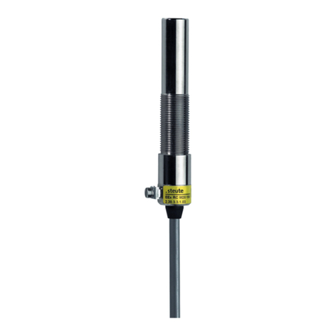
steute
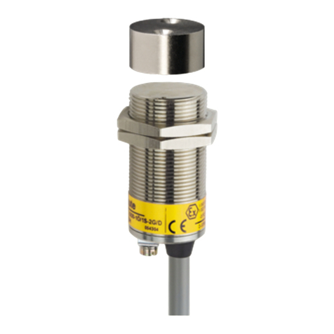
steute Ex RC-3G/D Series Programming manual
steute
steute Ex RC Si M30 Programming manual
steute
steute RF 96 LT SW868 Programming manual
steute
steute Ex RC Si M30 Programming manual
steute
steute RF 96 SDS SW868-NET Programming manual
steute
steute EEx HS Si 4 Programming manual
steute
steute EEx HS Si 4 Programming manual

steute
steute A-ESD Series Programming manual
