Stratus SAE-P410 User manual

Installation, Operation and Parts Manual
SAE-P410
2
SAFETY ........................................................................................................................................................................3
1.1 Operation of lifting platforms.............................................................................................................................................. 3
1.2 Checking of the lifting platforms ......................................................................................................................................... 3
1.3 Important safety notices...................................................................................................................................................... 4
1.4 Risks and safety instructions................................................................................................................................................ 5
PACKING AND TRANSPORTATION.................................................................................................................................6
2.1 Packing ................................................................................................................................................................................ 6
2.2 Lifting and handling............................................................................................................................................................. 6
2.3 Storage ................................................................................................................................................................................ 6
PRODUCTS DESCRIPTIONS............................................................................................................................................7
3.1 General descriptions............................................................................................................................................................ 7
3.2 General construction of the lift............................................................................................................................................ 7
3.3 Dimensions .......................................................................................................................................................................... 8
3.4 Technical data ..................................................................................................................................................................... 9
INSTALLATION INSTRUCTIONS......................................................................................................................................9
4.1 Preparations before installation.......................................................................................................................................... 9
4.2 Installation attentions ....................................................................................................................................................... 11
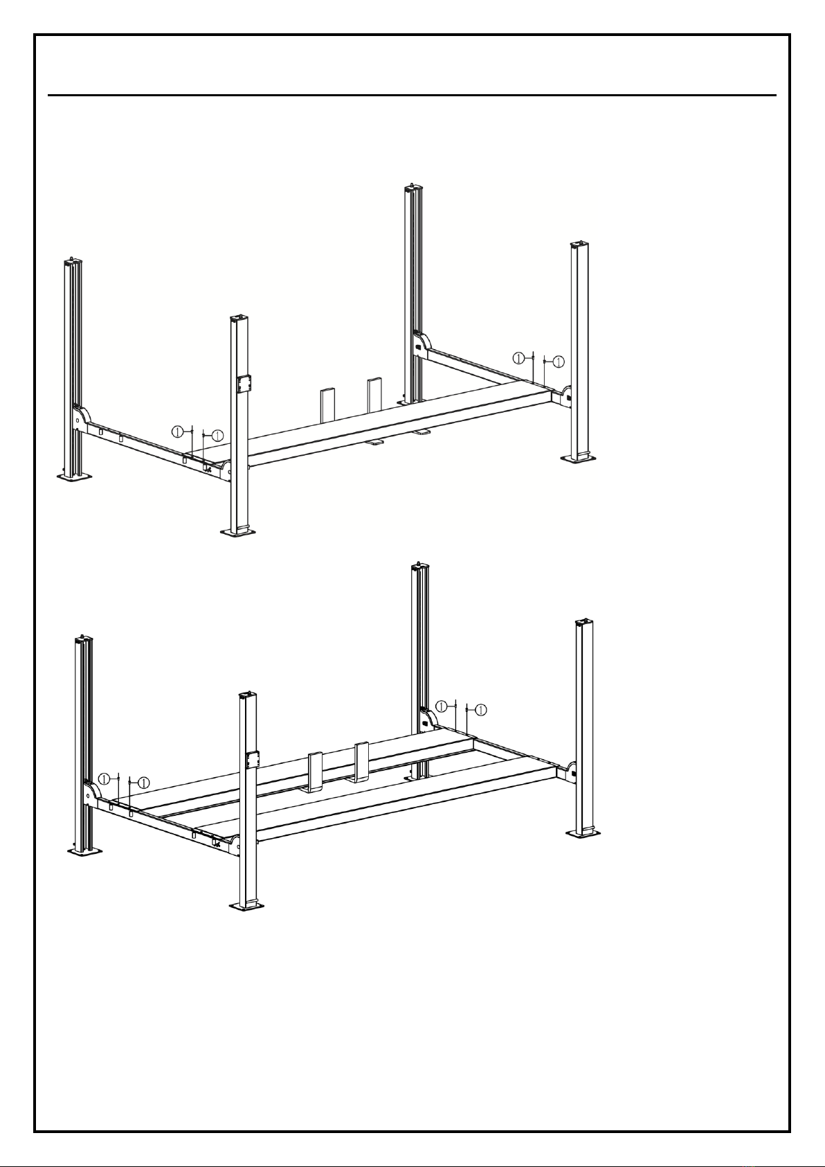
4.3 General Installation instructions........................................................................................................................................ 11
4.4. Items to be checked after installation .................................................................................................
错误
!
未定义书签。
OPERATION INSTRUCTIONS........................................................................................................................................19
5.1 Precautions........................................................................................................................................................................ 19
5.2 Operation instructions....................................................................................................................................................... 19
Annex 1, Hydraulic schemes and parts list .............................................................................................................................. 20
Annex 2, Electrical schemes and parts list............................................................................................................................... 23
Annex 3, Mechanical exploded drawings and parts list .............................................................................
错误
!
未定义书签。

Installation, Operation and Parts Manual
SAE-P410
3
SAFETY
1.1 Operation of lifting platforms
This lift is specially designed for vehicle parking. Users are not allowed to use it for any other purposes. The applicable national regulations,
laws and directives must be observed.
Only users aged 18 or above who have b n instructed on how to operate the lifting platform and have proven their ability to do so to the owner
are to be entrusted with unsupervised operation of lifting platforms. The task of operating the lifting platforms must be granted in writing.
Before loading a vehicle onto the lifting platform, users should study the original operation instructions and familiarize themselves with the
operating procedures in several trial runs.
Lift vehicle within the rated load. Don’t attempt to park vehicles with excessive weight.
1.2 Checking of the lifting platforms
Checks are to be based on the following directives and regulations:
⚫Basic principles for testing lifting platforms
⚫The basic health and safety requirements
⚫Harmonized European standards
⚫The applicable accident prevention regulations
The checks are to be organized by the user of the lifting platform. The user is responsible for appointing an expert or qualified person to
perform checking. It must be ensure that the person chosen satisfies the requirements.
The user bears special responsibility if employ s of the company are appointed as experts or qualified persons.
1.2.1 Scope of checking
Regular checking essentially involves performing a visual inspection and a functional test. This includes checking the condition of the
components and equipment, checking that the safety systems are complete and functioning properly and that the inspection log book is
completely filled in. The scope of exceptional checking depends on the nature and extent of any structural modification or repair work.
1.2.2 Regular checking
After initial commissioning, lifting platforms are to be checked by a qualified person at intervals of not longer than one year.
A qualified person is somebody with the training and experience required to possess sufficient knowledge of lifting platforms and who is
sufficiently familiar with the pertinent national regulations, accident prevention regulations and generally acknowledged rules of engine ring to
be able to assess the safe operating condition of lifting platforms.
1.2.3 Exceptional checking
Lifting platforms with a lift height of more than 2 meters and lifting platforms intended for use with people standing under the load bearing
elements of the load are to be checked by an expert prior or reuse following structural modifications and major repairs to load bearing
components.
An expert is somebody with the training and experience required to possess specialist knowledge of lifting platforms and who is sufficiently
familiar with the pertinent national work safety regulations, accident prevention regulations and generally acknowledged rules of engineering

Installation, Operation and Parts Manual
SAE-P410
4
to be able to check and give an expert option on lifting platforms.
1.3 Important safety notices
1.3.1 Recommend for indoor use only. DO not expose the lift to rain, snow or excessive moisture.
1.3.2 Only use this lift on a surface that is stable, level and dry and not slippery, and capable of sustaining the load. Do not install the lift on
any asphalt surface.
1.3.3 Read and understand all safety warnings before operating the lift.
1.3.4 Do not leave the controls while the lift is still in motion.
1.3.5 Keep hands and feet away from any moving parts. Keep feet clear of the lift when lowering.
1.3.6 Only these properly trained personnel can operate the lift.
1.3.7 Do not wear unfit clothes such as large clothes with flounces, tires, etc., which could be caught by moving parts of the lift.
1.3.8 To prevent evitable incidents, surrounding areas of the lift must be tidy and with nothing unconcerned.
1.3.9 The lift is simply designed to lift the entire body of vehicles, with its maximum weight within the lifting capacity.
1.3.10 Always insure the safety locks are engaged before any attempt to work near or under the vehicle. Never remove safety related
components from the lift. Do not use if safety related components are damaged or missing.
1.3.11 Do not rock the vehicle while on the lift or remove any heavy component from vehicle that may cause excessive weight shift.
1.3.12 Check at any time the parts of the lift to ensure the agility of moving parts and the performance of synchronization. Ensure regular
maintenance and if anything abnormal occurs, stop using the lift immediately and contact our dealers for help.
1.3.13 Lower the lift to its lowest position and do remember to cut off the power when not using the lift.
1.3.14 Do not modify any parts of the lift without manufacturer’s advice.
1.3.15 If the lift is going to be left unused for a long time, users are required to:
a. Disconnect the power;
b. Empty the oil tank;
c. Lubricate the moving parts with hydraulic oil.
WARNING:The warnings, cautions and instructions discussed in this instruction manual cannot cover all possible conditions and situations
that may occur. It must be understood by the operator that common sense and caution are factors which cannot be built into this product,
but must be supplied by the operator.
CAUTION1:ALWAYS ensure the mechanical safety locks are engaged parking. Never remove safety
related components from the lift. Do not use if safety related components are damaged or missing.
CAUTION2: Failure installation and operation or any improper modification could result in hurts or even
death of operators. Please do read and understand this manual thoroughly and operate as it required.

Installation, Operation and Parts Manual
SAE-P410
5
1.4 Risks and safety instructions
During lift functioning, the operator shall stand in a safe area.
The presence of persons beneath the cross-pieces and/or the platforms when they are moving, or the presence of persons inside the danger
zone is strictly prohibited. During operations persons are admitted to the area beneath the vehicle only when the vehicle is already in the
elevated position, when the cross-pieces and platforms are stationary, and when the mechanical safety devices (wedges) are firmly engaged in
the slots on the safety rods.
RISK OF CRUSHING
When the platforms and the vehicle are lowering, make sure no vehicle is beneath the parking platform.
When the platforms and the vehicle are lowering, personnel are prohibited from entering the area beneath the movable parts of the lift
The lift operator must not start the lift until it has been clearly established that there are no persons in danger zone
RISK OF IMPACT
IMPACT caused by the parts of the lift or the vehicle that are positioned at head height.
When, due to operational reasons, the lift is stopped at relatively low elevations(less than 1.75 m from the ground) personnel must be careful
to avoid impact with parts of the machine not marked with special colors.
RISK OF VEHICLE MOVING
MOVING caused by operations involving the application of force sufficient to displace the vehicle.
In the case of large or particularly heavy vehicles, sudden movement could create an unacceptable overload or uneven load sharing.
Therefore, before lifting the vehicle and during all operations on the vehicle MAKE SURE THAT IT IS PROPERLY STOPPED BY THE HAND
BRAKE. .
RISK OF VEHICLE FALLING FROM LIFT
This hazard may arise in the case of incorrect positioning of the vehicle on the platforms, incorrect stopping of the vehicle, or in the case of
vehicles of dimensions that are not compatible with the capacity of the lift.
RISK OF SLACKENING OF LIFT CABLES
SLACKENING caused by objects left leaning against the posts or on the platforms.
RISK OF SLIPPING
SLIPPING caused by lubricant contamination of the floor around the lift
THE AREA BENEATH AND IMMEDIATELY SURROUNDING THE LIFT AND ALSO THE PLATFORMS MUST BE KEPT CLEAN.
REMOVE ANY OIL SPILLS IMMEDIATELY.
RISKS RELATED TO IMPROPER USE
Persons are not permitted to stand or sit on the platforms during the lifting process or when the vehicle is already lifted.

Installation, Operation and Parts Manual
SAE-P410
6
PACKING AND TRANSPORTATION
Packing, lifting, handling, transporting operations must be performed only by experienced personnel with appropriate
knowledge of the lift and after reading this manual.
2.1 Packing
The lift is shipped with two parts
Name
Packed by
Dimension
Weight
Quantity
Lift
Steel bracket
198-13/16”x 24-7/16” x26 -15/16”
2750 lbs.
1
oil drip pans
Bubble film
37-3/8”x 23-5/8”x 2-3/8”
11 lbs.
1 (8 pcs)
2.2 Lifting and handling
The packs can be lifted and transported only by using lift trucks .Never attempt to hoist or transport the unit using lifting straps.
Opening the packs
When the lift is delivered make sure that it has not been damaged during transportation and that all the parts specified on the packing list are
present.
Packs must be opened adopting all the precautions required to avoid injury to persons (keep at a safe distance when cutting the straps) or
damage to parts of the machine (be careful that no parts are dropped while you are opening the packing)
Take special care with the hydraulic power unit, the control panel and the platform cylinder.
2.3 Storage
The packs must be kept in a covered and protected area in a temperature range of -10℃to +40℃. They must not be exposed to direct
sunlight.
Stacking the packs
We advise against stacking because the packs are not designed for this type of storage. The narrow base, heavy weight and large size of the
packs make stacking difficult and potentially dangerous.
If stacking is unavoidable, use all appropriate precautions:
-never stack to more than 2 meters in height.
-never make stacks of single packs. Always stack pairs of packs in a cross pattern so that the base is bigger and the resulting stack is more
stable. Once the stack is complete, restrain it using straps, ropes or other suitable methods.
A maximum of two packs can be stacked on lorries, in containers, and in railway wagons, on condition that the packs are strapped together
and restrained to stop them falling.

Installation, Operation and Parts Manual
SAE-P410
7
PRODUCTS DESCRIPTIONS
3.1 General descriptions
This four post lift is generally composed by four posts, two beams, two platforms, a hydraulic oil cylinder and a set of power unit. It is driven by
an electro-hydraulic system. Up and down of platforms is controlled by the to and fro movement of the oil cylinder. It is equipped with
mechanical safety locks in the four posts, which is to prevent the platforms from sudden dropping down in case the hydraulic system fails to
work.
3.2 General construction of the lift
1.Power side post
7.Wheel retainer
2.Post
8.Drive-on ramp
3.Power side crossbeam
9.Tool tray
4.The secondary crossbeam
10.Power unit
5.Main platform
11.Mobile kit (optional )
6.Secondary platform

Installation, Operation and Parts Manual
SAE-P410
8
3.3 Dimensions

Installation, Operation and Parts Manual
SAE-P410
9
3.4 Technical data
Power type
Electro-hydraulic
Maximal Capacity
10000 lbs.
Full rise height
77-9/16”
Initial height
5-1/2”
Full rise time
≤70S
Full descending time
≤60S
Working pressure
≥2900PSI.
Power supply
110V-1PH-60HZ
Motor capacity
2.2kW
Oil tank volume
3.17 us gal
Noise
< 75Db
INSTALLATION INSTRUCTIONS
4.1 Preparations before installation
4.1.1 Space requirements.
This lift is for indoor use only.
To stop vehicles colliding with the ceiling, it is advisable to fit an overhead light barrier in low ceiling buildings.
Refer to 3.3 for the dimensions of the lift. There must be a clearance of at least 39 3/8” between the lifting platform and fixed elements (e.g.
wall) in all lifting positions.
There must be sufficient space at the ends of the lifting platform for driving vehicles on and off.
4.1.2 Foundations and connections
The user must have the following work performed before erecting the lift.
⚫Construction of the foundation following consultation with the manufacturer’s customer service or an authorized service agent.
⚫Routing of the wiring to the installation location. The user must provide fuse protection for the connection. For Voltage between 100V
to 240V, it is advised to use C32 circuit breaker. For Voltage between 380V to 415V, it is advised to use C16 circuit breaker.
Requirements for power supply cable of the installation site: at least 1/8 sq. inch wire core for 3Ph power and 3/16 sq. inch wire core
for 1Ph power.
⚫Routing of the compressed air connection to the installation location. The user must install a service unit upstream of the connection.
Refer also to the corresponding information in the operation instructions.
4.1.3 Foundations preparations
Only use this lift on a surface that is stable, level and dry and not slippery, and capable of sustaining the load.
C20/25 concrete base with strength more than 3000psi. Minimum thickness of7-7/8”.
Surface: Horizontal and even (Gradients max. 0.5 %)

Installation, Operation and Parts Manual
SAE-P410
10
Newly built concrete ground must be older than 20days.
4.1.4 Tools and equipment needed for installation
Tool name
Specification
Quantity
Open spanner
D17-19, D22-24
2
Hex socket spanner
D2.5-14
1
Adjustable spanner
Above D30
1
Cross socket screw driver
PH2
1
Socket spanner
D24
1
Torque spanner
MD400
1
Levelling device
Accuracy 1/16”
1
Truck lift
Capacity more than 6600 lbs.
1
Strap
Capacity more than 2200 lbs.
1
4.1.5 Checking parts
Unfold the package and check if any parts missed as per the following list. Do not hesitate to contact us in case any parts missed.
S/N
Name
Qty
NOTE
1
Main lifting platform
1
Package 1
2
Secondary lifting platform
1
3
Power side post
1
4
Post
3
5
Power side crossbeam
1
6
Secondary crossbeam
1
7
Wheel retaining tube
2
8
Protective cover
4
9
Drive-on ramp
2
10
Tool tray
1
11
Power unit
1
12
Oil hose
1
13
Expansion bolt M16*120
16
14
Hex head full swivel screw M12*25
16
15
Hex socket flat head screw M12*25
8
16
Hex head full swivel screw M8*20
4
17
Spring washer Ф12
16
18
Spring washeФ8
4
19
Flat washer Ф8
4
20
Anti-shock pad
4
21
User's Manual 6435E.V2
1
22
Oil dip tray
8
Package 2

Installation, Operation and Parts Manual
SAE-P410
11
4.2 Installation attentions
4.2.1 Joints of oil hose and wiring must be firmly connected in order to avoid leakage of oil hose and looseness of electrical wires.
4.2.2 All bolts should be firmly screwed up.
4.2.3 Do not place any vehicle on the lift in the case of trial running.
4.3 General Installation instructions
Step 1: Fix the installation layout.
Mark the four standing points of the four posts on the installation site by a tape measure and chalk. Ensure two diagonal lines are of the same
length.
Step 2: Remove the packing materials.
Attention: Packs must be opened adopting all the precautions required to avoid injury to persons (keep at a safe distance when cutting the
straps) or damage to parts of the machine (be careful that no parts are dropped while you are opening the packing)
Take special care with the hydraulic power unit, the power unit and the platform cylinder.
Avoid scratching the painting surface and hoses.
1. Place some wooden battens (thickness of which should be more than 3”) on the ground (other dependable devices may also applicable) and
then use forklift to have the packing rack removed on to the battens.
2. Have the platforms of the lift suspended by the forklift and then screw off the upside bolt and remove the first platform on to the wooden
battens initially prepared.
3. Screw off the downside bolt and take away the packing racks on both sides.
4. Remove the shock absorption plastic film with a knife.

Installation, Operation and Parts Manual
SAE-P410
12
Step 3: Use the forklift to have the general parts properly positioned.
For convenient installation, it would be better to pad something supporting under the platform.
Oil cylinder, steel cable and oil hose have already been fixed in the power side platform (platform with oil cylinder beneath) before packing.
Step 4: Connect the platforms and beams.
1. Place the two post face to face with a distance of 120 7/8” and then push in the crossbeam from the top of the posts.
2. Erect the posts after both crossbeams was connected.

Installation, Operation and Parts Manual
SAE-P410
13
Step 5: Mount on the top post plate and fix safety ratchets.
1. Fix ratchet with the top post plate with M20 hex nut and flat washer. Ensue the four safety ratchets are of the same height from the ground,
This could be checked by measuring the distance of the lowest square hole reserved on the ratchet and the floor.
2. Fix the top post plate with the post using M12*25 hex head screw, spring washer and flat washer.
①Top post plate ;② M12*25 hex screw ;③ φ12 spring washer;④ φ12 flat washer ⑤ safety ratchet ⑥ M20 nut ⑦ φ20 flat washer
Step 6: Mount on lifting platforms
1. Raise both crossbeams to the first locking points.

Installation, Operation and Parts Manual
SAE-P410
14
2. Lift the platform with proper lifting equipment and place it onto the crossbeams. Fix the lifting platform and the crossbeam with M12*25
hex socket flat head screw.
①Hex socket flat head screw M12*25

Installation, Operation and Parts Manual
SAE-P410
15
3. Fix the installation plate for drive-on ramps
① Installation plate for drive-on ramp ② M16*25 hex head screw ③ Flat washer
Step 7: Fix transfer bar.
Insert the two section of the transfer bar respectively to the swing shaft assemblies in both crossbeams. Connect the two sections into a whole
with screws.
① Transfer bar; ②Connection tube; ③M8*10 Hex socket flat head locking screw; ④Main swing shaft; ⑤Secondary swing shaft

Installation, Operation and Parts Manual
SAE-P410
16
Step 8: Fix steel cables and relevant accessories.
1. Route and fix steel cables;
2. Fix crossbeam protective covers;
3. Install release handle;
① steel cable; ②M20 hex nut; ③20 flat washer; ④M20 hex nut; ⑤ Protective cover; ⑥8*12 hex socket button head screw;
⑦φ8 flat washer; ⑧ Release handle; ⑨M6*30 hex head screw

Installation, Operation and Parts Manual
SAE-P410
17
Step 9: Connect hydraulic hoses and electrical wires.
Refer to electrical and hydraulic connection diagrams before making connection.
Refer to Annex 1 when fix the hydraulic system.
Attention: Connect oil hoses as per the marks on the hoses and do not contaminate the hydraulic components during the connection.
Refer to Annex 2 when fix the electrical system.
Attention: For three phase power supply, if the lift doesn't raise and the motor may turn in the wrong direction, in such event, interchange wires
U, V in the control cabinet.
Step 10: Fill with hydraulic oil
ONLY CLEAN AND FRESH OIL ONLY .Lift must be fully lowered before changing or adding hydraulic oil.
Fill about 2.7 us gal oil into the oil tank. The level of oil shall reach the tippets volume mark of the tank.
Run the lift for several cycles and add more oil until the lifting platform can reach its maximum height.
Note:As running speed of the lift is mainly decided by the viscosity of the hydraulic oil, we suggest using NO.46 hydraulic oil when average
temperature of the location is above 18 degree Celsius and using NO.32 hydraulic oil when temperature is below 18 degree Celsius.
Change the oil 6 months after initial use and change once per year thereafter.
Step 11: Check the steel cable connection and check the function of mechanical locks.
1. Check the steel cable connection
Switch on and press the UP button until the steel cable is fully extended. Check if the steel cable is in the slot of the pulley.
2. Check the function of mechanical locks.
Raise the platform above its first locking point. Push the down button to see of the four corners of the platform are locked. If not being
simultaneously locked, one side or one end of the platform could be slanted. Adjust screw 1 which is indicated in the below drawing at the
corresponding corner until the four locks can be engaged simultaneously.
Push the UP button to release the mechanical locks .Push down the mechanical release handle and meanwhile push unloading handle to lower
the platform to see if four mechanical locks can be released. If not adjust nut 1 at the corresponding corner.
Step 12: Level the platform
Attention: No vehicle on platforms when levelling.
1. Check and adjust the tension of steel cable.
Lower and raise the platform within 16” for several cycles. Raise the platform about 19-1/2” high off the ground and measure the height at four
corners of the platform. Adjust the nut that fix steel cable until the height measured at the four corners is almost the same.

Installation, Operation and Parts Manual
SAE-P410
18
2. Secondly, level the platforms after mechanical safety locks are engaged.
Raise the platform about 31” high and push the unloading handle to engage the mechanical safety lock. Judge if the mechanical locks could be
engaged synchronously by listening to the sound. Engage the mechanical lock and measure the height at four corners of the platform. In case
the height is different, adjust the nut (M20) that fix the safety ratchet and the top plate of the post until the height measured at the four
corners is almost the same.
Step 13: Fix the expansion anchoring bolts
Refer to 3.3 and adjust the distance between posts before drilling holes for expansion bolts.
1. Drill anchor holes for the bolts on the installation foundation with an electrical drill. Make sure to drill vertically.
2. Remove thoroughly the debris and dust in holes and ascertain that the posts stay right upon the circle previously marked by chalk.
3. Hammer in and secure expansion bolts.
Step 14: Grease movable parts with NO.1 lithium base grease.
Grease steel ropes/ pulleys/ sliders.
4.4. Items to be checked after installation
S/N
Check items
YES
NO
1
Screw torque of expansion bolts : 60-80N•m;
√
2
Rising speed ≥20mm/s;
√
3
Noise with rated load ≤75dB(A);
√
4
Grounding resistance: not bigger than 4Ω;
√
5
Height difference of the two carriages ≤5mm;
√
6
Mechanical catch unit is robust and synchronized when running with rated load ;
√
7
If the control button works as “hold to run”?
√
8
If grounding wire is connected?
√
9
If rising and lowering smoothly?
√
10
If there is no abnormal notice during running with rated load?
√
11
If there is no oil leakage when running with rated load?
√
12
If there is no air leakage when running with rated load?
√
13
If expansion bolts, nuts or circlips are well secured?
√
14
If the max lifting height is 77 9/16”?
√
15
If Safety advices, name plate and logos are clear?
√

Installation, Operation and Parts Manual
SAE-P410
19
OPERATION INSTRUCTIONS
5.1 Precautions
5.1.1 Check all connections of oil hose. Only when there is no leakage, the lift can start work.
5.1.2 The lift, if its safety device malfunctions, shall not be used.
5.1.3 It shall not lift or lower an automobile if its center of gravity is not positioned midway of the runways. Otherwise, we as well as our
dealers will not bear any responsibility for any consequence resulted thereby.
5.1.4 Operators and other personnel concerned should stand in a safety area during lifting and lowering process.
5.1.5 Make sure the mechanical safety lock of the lift is engaged before start working under the vehicle and no people under the vehicle during
lifting and lowering process.
5.2 Operation instructions
To avoid personal injury and/or property damage, permit only trained personnel to operate the lift. After reviewing these ins tructions,
get familiar with lift controls by running the lift through a few cycles before loading vehicle on lift. Do not attempt to transport a load
on the lift. The lift must be only used in a static position for lifting and lowering vehicles.
Ascending
There must be sufficient space for parking. Pay close attention to the vehicle roof during ascending process so as to stop
vehicles colliding with the ceiling.
Make sure vehicle is neither front nor rear heavy and center of balance should be midway between adapters and centered
over the lift.
1. Connect the main power cable.
2. Park the vehicle on the platforms to ensure its gravity is positioned midway of the platforms.
3. Push the UP button until platforms rise to expected height.
4. Push the handle of unloading valve to engage the mechanical safety lock.
5. Place the oil dip tray properly and park the other vehicle under the platform
Descending
When lowering the lift pay careful attention that all personnel and objects under are kept clear.
1. Drive away the vehicle under the platform
2. PUSH the UP button to release the mechanical locks.
3. PUSH down the release handle and the unloading handle to lower the platform
4. Drive away the vehicle parking on the platform when the lift is fully lowered.

Installation, Operation and Parts Manual
SAE-P410
20
Annex 1, Hydraulic schemes and parts list
1.Oil tank
2.Oil sucking filter
3.Gear pump
4.Coupling
5.Motor
6.Composite hydraulic block
7.Cushion valve
8.Over-flow valve
9.Single way valve
10.Manual unloading valve
11.Throttle valve
12.Oil tank cover
13.Hydraulic cylinder
14.Oil sucking tube
Table of contents
Other Stratus Lifting System manuals

Stratus
Stratus SAE-UT8000 Guide

Stratus
Stratus SAE-C10XE Guide

Stratus
Stratus SAE-F10S Installation instructions

Stratus
Stratus SAE-C9P Guide

Stratus
Stratus SAE-F14X Guide

Stratus
Stratus SAE-P166M Guide

Stratus
Stratus SAE-C12XE Guide

Stratus
Stratus SAE-C12X Guide

Stratus
Stratus SAE-F12X Guide

Stratus
Stratus SAE-UT9000 Guide
Popular Lifting System manuals by other brands

CLASSIC LIFT
CLASSIC LIFT CL6500-4P Installation and service manual

Cobra
Cobra Maxilift 5500 Use and maintenance manual

Lift Tech Marine
Lift Tech Marine AC AUTO STOP GEN 2 owner's manual

National ramp
National ramp 2470-01 Quick installation guide

TrestleJacks USA
TrestleJacks USA TJ470 owner's manual

Atlas
Atlas BP10000 Installation & operation manual