manuals.online logo
Brands
  1. Home
  2. •
  3. Brands
  4. •
  5. Sunricher
  6. •
  7. Controllers
  8. •
  9. Sunricher SR-2411-ZG-DIM User manual

Sunricher SR-2411-ZG-DIM User manual

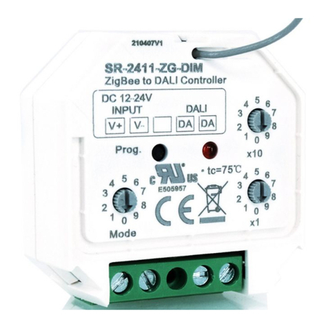
ZigBee to DALI DT6 Controller
09.2411ZGDIM.04791
Function introduction
Important: Read All Instructions Prior to Installation
Input signal
Output
Power Supply
DALI Current Consumption
Operating temperature
Relative humidity
Dimensions(LxWxH)
Radio frequency
Product Data
• DO NOT install with power applied to device.
• DO NOT expose the device to moisture.
Safety & Warnings
ZigBee/Push
DALI signal
12-24VDC
<4mA
0-40°C
8% to 80%
45.5x45x20.3mm
2.4GHz
• ZigBee to DALI DT6 Controller based on ZigBee 3.0
• Receives ZigBee signal and outputs DALI signal to DALI line, 12-24VDC power supply
• Comply to DALI standard protocol IEC 62386-102, IEC 62386-207 and in compliance with DALI products from other
international incorporations
• ZigBee end device that supports Touchlink commissioning
• Supports zigbee green power and can learn to max. 20 zigbee green power remotes
• Can directly pair to a compatible ZigBee remote through Touchlink
• Compatible with universal ZigBee gateway products
• Supports self-forming zigbee network without coordinator
• Enables to add devices to the self-formed zigbee network
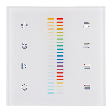
• Compatible with universal ZigBee dim remotes
• DALI bus current consumption <4mA
• Enable to select Group control or Address control to DALI line by a rotary switch
• Enable to control 1 DALI Group of devices or 1 DALI Address on DALI line
• Enable to control all devices on DALI line via broadcast
• Enable to select any DALI Group (0-15) or DALI Address (00-63) to control by rotary switches
• Each DALI line can install multiple controllers for multi control points
• Waterproof grade: IP20
1. Select DALI Address/Group Control Mode:
1) A rotary switch is used to select Address/Group control mode.
2) When the rotary switch arrow is at Add. position, address control mode is selected.
3) When the rotary switch arrow is at Group position, group control mode is selected.
2. Select DALI Address to be Controlled:
1) When Address control mode is selected, use the two rotary switches for setting address number (00-64) to
select the DALI address (00-63) you would like to control, the number equals to tens position plus units
position.
2) Set the address number as 0, all DALI devices on the circuit will be controlled through broadcast.
3) Set the address number as X except 0 (01-64), control gear with DALI address X-1 will be controlled.
Note: if X is set as 64, control gears with DALI address 63 will be controlled by the controller.
3. Select DALI Group to be Controlled:
1) When Group control mode is selected, use the two rotary switches for setting group number to select the
DALI group (0-15 selectable) you would like to control, the number equals to tens position plus units position.
2) This DALI controller enables on/off and dimming commands to be sent to 1 Group of devices on the DALI
circuit.
3) When group number is set as 0, all DALI devices on the circuit will be controlled through broadcast.
4) When group number is set as X except 0 (1-15), the controller will control DALI Group X-1.
Note: Please first group all DALI control gears on the circuit by a master controller.
Please refer to the detailed Group setting table as follows:
4. This ZigBee device is a wireless receiver that communicates with a variety of ZigBee compatible
systems. This receiver receives and is controlled by wireless radio signals from the compatible ZigBee
system.
Group Number
Setting
DALI Group
Selected
0
Broadcast
1
0
2
1
3
2
4
3
5
4
6
5
7
6
8
7
9
8
10
9
11
10
12
11
13
12
14
13
15
14
Operation
Input Clusters
• 0x0000: Basic • 0x0003: Identify • 0x0004: Groups • 0x0005: Scenes
• 0x0006: On/off • 0x0008: Level Control • 0x0b05: Diagnostics
Output Clusters
• 0x0019: OTA
ZigBee Clusters the device supports are as follows:
DADA
ZigBee to DALI Controller
Prog.
Rotary Switch to select
Group or Address
control to DALI circuit
DALI signal outputDC12-24V power input
Program key for factory
reset the controller LED indicator
Add.Group
1*(0~9) for setting
units position
10*(0~9) for setting
tens position
Rotary switches for setting DALI Group number (0-15) or
Address number (0-63) to be controlled, the number equals to
tens position plus units position
x1
x10
5
0
1
6
2
7
4
9
3
8
5
0
1
6
2
7
4
9
3
8
DC 12-24V
INPUT
V+ V-
DALI
OUTPUT
< 10cm
DALI bus
DA DA
DADA
ZigBe e to D ALI Con tr oll er
Pro g.
Add .Gro up x 1
x10
5
0
1
6
2
7
4
9
3
8
5
0
1
6
2
7
4
9
3
8
DC 12 -24V
INP UT
V+ V-
DAL I
OUT PUT
12V/24V
CV PSU
L
NV+
OUTPUT
INPUT
GV-
L N G
5. Zigbee Network Pairing through Coordinator or Hub (Added to a Zigbee Network)
Step 1: Remove the device from previous zigbee network if it has already been added to, otherwise pairing will
fail. Please refer to the part "Factory Reset Manually".
Step 2: From your ZigBee Controller or hub interface, choose to add lighting device and enter Pairing mode as
instructed by the controller.
Step 3: Reset power of the controller
to set the device to network pairing
mode (LED indicator flashes twice
slowly), 15 seconds timeout, repeat
this step.
Step 4: LED indicator will blink 5 times and then
stay solid on, then the device will appear in your
controller's menu and can be controlled through
controller or hub interface.
8. Factory Reset Manually
Step 2: LED indicator will blink 3 times to indicate successful reset.
Step 1: Short press “Prog.” key for 5 times continuously or reset
power of the controller 5 times continuously if the “Prog.” key is not
accessible.
Note: 1) If the device is already at factory default setting, there is no indication when factory reset again .
2) All configuration parameters will be reset after the device is reset or removed from the network.
6. TouchLink to a Zigbee Remote
Step 1: Method 1: Short press “Prog” button 4 times (or reset power of the controller 4 times) to start Touchlink
commissioning immediately under any circumstance, 180S timeout, repeat this step.
Method 2: Reset power of the controller, Touchlink commissioning will start after 15S if it’s not added to a
zigbee network, 165S timeout. Or start immediately if it’s already added to a network, 180S timeout. Once
timeout, repeat the operation.
Step 2: Bring the remote or touch
panel within 10cm of the lighting
device.
Step 3: Set the remote or touch
panel into Touchlink
commissioning,
please refer to corresponding
remote or touch panel manual to
learn how.
Step 4: There shall be indication on the remote for successful link and
LED indicator will flash twice.
Note: 1) Directly TouchLink (both not added to a ZigBee network), each device can link with 1 remote.
2) TouchLink after both added to a ZigBee network, each device can link with max. 30 remotes.
3) For Hue Bridge & Amazon Echo Plus, add remote and device to network first then TouchLink.
4) After TouchLink, the device can be controlled by the linked remotes.
7. Removed from a Zigbee Network through Coordinator or Hub Interface
From your ZigBee controller or hub
interface, choose to delete or reset the
lighting device as instructed. The
connected light blinks 3 times to indicate
successful reset.
Zigbee
Remote
DALI bus
DA DA
DADA
ZigBe e to D ALI Con tr oll er
Pro g.
Add .Gro up x 1
x10
5
0
1
6
2
7
4
9
3
8
5
0
1
6
2
7
4
9
3
8
DC 12 -24V
INP UT
V+ V-
DAL I
OUT PUT
12V/24V
CV PSU
L
NV+
OUTPUT
INPUT
GV-
L N G
DALI bus
DA DA
DADA
ZigBe e to D ALI Con tr oll er
Pro g.
Add .Gro up x 1
x10
5
0
1
6
2
7
4
9
3
8
5
0
1
6
2
7
4
9
3
8
DC 12 -24V
INP UT
V+ V-
DAL I
OUT PUT
12V/24V
CV PSU
L
NV+
OUTPUT
INPUT
GV-
L N G
DAL I Co ntr oll er
123
4
0-6 0- 9
DA
DA
DA
DA
DALI D ALI
V+
V-
V+
V-
12-3 6VDC
INPU T
DAL I Co ntr oll er
123
4
0-6 0- 9
DA
DA
DA
DA
DALI D ALI
V+
V-
V+
V-
12-3 6VDC
INPU T
DAL I Co ntr oll er
123
4
0-6 0- 9
DA
DA
DA
DA
DALI D ALI
V+
V-
V+
V-
12-3 6VDC
INPU T
10. Find and Bind Mode
Step 1: Short press “Prog.” button 3 times (Or reset power of the controller 3 times) to
set the device (initiator node) to start Find and Bind mode (LED indicator flashes
slowly) to find and bind target node, 180 seconds timeout, repeat this step.
Zigbee
Remote
Step 2: Set the remote or touch
panel (target node) into find and
bind mode, and enable it
to find and bind initiator, please
refer to corresponding remote or
touch panel manual.
Step 3: There shall be indication
on the remote or touch panel that
it bind the device successfully
and can control it then.
Note: Make sure the device and remote already added to the same zigbee network.
11. Learning to a Zigbee Green Power Remote
Step 1: Short press “Prog.” button 4 times (Or reset power of the controller 4 times) to start
Learning mode (LED indicator flashes twice), 180 seconds timeout, repeat the operation.
Step 2: Set the green power
remote into Learning mode,
please refer to its manual.
Step 3: LED indicator will flash twice to indicate successful learning. Then the remote can control the device.
Note: Each device can learn to max. 20 zigbee green power remote.
12. Delete Learning to a Zigbee Green Power Remote
Step 1: Short press “Prog.” button 3 times (Or reset power of the controller 3 times) to start delete
Learning mode (LED indicator flashes slowly), 180 seconds timeout, repeat this step.
Zigbee
Green Power
Remote
Step 2: Set the paired green
power remote into Learning
mode, please refer to its manual.
Step 3: LED indicator will flash 4 times to indicate successful deleting.
9. Factory Reset through a Zigbee Remote (Touch Reset)
Note: Make sure the device already added to a network, the remote added to the same one or not added to any
network.
Step 1: Reset power of the
controller to start
TouchLink Commissioning
of the device, 180 seconds
timeout, repeat this step.
Step 4: There shall be indication on the remote and
LED indicator flashes 3 times for successful reset.
Step 2: Bring the remote or touch panel
within 10cm of the lighting device.
Step 3: Set the remote or touch
panel into Touch Reset procedure
to reset the device, please refer to
corresponding remote or touch
panel manual to learn how.
Zigbee
Remote < 10cm
DALI bus
DA DA
DADA
ZigBe e to DALI C ontro lle r
Pro g.
Add .Gro up x 1
x10
5
0
1
6
2
7
4
9
3
8
5
0
1
6
2
7
4
9
3
8
DC 12 -24V
INP UT
V+ V-
DAL I
OUT PUT
12V/24V
CV PSU
L
NV+
OUTPU T
INPUT
GV-
L N G
Zigbee
Green Power
Remote
DALI bus
DA DA
DADA
ZigBe e to DALI C ontro lle r
Pro g.
Add .Gro up x 1
x10
5
0
1
6
2
7
4
9
3
8
5
0
1
6
2
7
4
9
3
8
DC 12 -24V
INP UT
V+ V-
DAL I
OUT PUT
12V/24V
CV PSU
L
NV+
OUTPU T
INPUT
GV-
L N G
DALI bus
DA DA
DADA
ZigBe e to DALI C ontro lle r
Pro g.
Add .Gro up x 1
x10
5
0
1
6
2
7
4
9
3
8
5
0
1
6
2
7
4
9
3
8
DC 12 -24V
INP UT
V+ V-
DAL I
OUT PUT
12V/24V
CV PSU
L
NV+
OUTPU T
INPUT
GV-
L N G
DALI bus
DA DA
DADA
ZigBe e to DALI C ontro lle r
Pro g.
Add .Gro up x 1
x10
5
0
1
6
2
7
4
9
3
8
5
0
1
6
2
7
4
9
3
8
DC 12 -24V
INP UT
V+ V-
DAL I
OUT PUT
12V/24V
CV PSU
L
NV+
OUTPU T
INPUT
GV-
L N G
DAL I Co ntr oll er
123
4
0-6 0- 9
DA
DA
DA
DA
DALI D ALI
V+
V-
V+
V-
12-3 6VDC
INPU T
DAL I Co ntr oll er
123
4
0-6 0- 9
DA
DA
DA
DA
DALI D ALI
V+
V-
V+
V-
12-3 6VDC
INPU T
DAL I Co ntr oll er
123
4
0-6 0- 9
DA
DA
DA
DA
DALI D ALI
V+
V-
V+
V-
12-3 6VDC
INPU T
DAL I Co ntr oll er
123
4
0-6 0- 9
DA
DA
DA
DA
DALI D ALI
V+
V-
V+
V-
12-3 6VDC
INPU T
14. OTA
The device supports firmware updating through OTA, and will acquire new firmware from zigbee controller or
hub every 10 minutes automatically.
Note: 1) Each added device can link and be controlled by max. 30 added remotes.
2) Each added remote can link and control max. 30 added devices.
13. Setup a Zigbee Network & Add Other Devices to the Network (No Coordinator Required)
Step 1: Short press “Prog.” button 4 times (Or reset power of the controller 4 times) to
enable the device to setup a zigbee network (LED indicator flashes twice) to discover and
add other devices, 180 seconds timeout, repeat this step.
Zigbee
Remote
Step 2: Set another device or remote or touch panel into network pairing mode and pair to the network, refer to
their manuals.
Step 3: Pair more devices and remotes to the network as you would like, refer to their manuals.
Step 4: Bind the added devices and remotes through Touchlink so that the devices can be controlled by the
remotes, refer to their manuals.
< 10cm
TouchLink
Zigbee Lighting Device
Wiring Diagram
45.00 mm
45.50 mm
20.3 mm
Product Dimension
DALI Con tr ol le r
123
4
0-6 0 -9
DA
DA
DA
DA
DAL I DALI
V+
V-
V+
V-
12- 36VD C
INP UT
DALI bus
DA DA
DADA
ZigBee to DALI C ontroller
Prog .
Add.Grou p x1
x10
5
0
1
6
2
7
4
9
3
8
5
0
1
6
2
7
4
9
3
8
DC 12-24V
INPUT
V+ V-
DALI
OUTPUT
12V/24V
CV PSU
L
NV+
OUTPUT
INPUT
GV-
L N G
DALI bus
DA DA
DADA
ZigBe e to DALI C ontro lle r
Pro g.
Add .Gro up x 1
x10
5
0
1
6
2
7
4
9
3
8
5
0
1
6
2
7
4
9
3
8
DC 12 -24V
INP UT
V+ V-
DAL I
OUT PUT
12V/24V
CV PSU
L
NV+
OUTPU T
INPUT
GV-
L N G
DAL I Co ntr oll er
123
4
0-6 0- 9
DA
DA
DA
DA
DALI D ALI
V+
V-
V+
V-
12-3 6VDC
INPU T

Other Sunricher Controllers manuals

Sunricher SR-2830RGB User manual

Sunricher

Sunricher SR-2830RGB User manual

Sunricher SR-2411-ZG-DIM User manual

Sunricher

Sunricher SR-2411-ZG-DIM User manual

Sunricher SR-2108HT(WP) User manual

Sunricher

Sunricher SR-2108HT(WP) User manual

Sunricher SR-2834BDMX User manual

Sunricher

Sunricher SR-2834BDMX User manual

Sunricher SR-ZV9001T-CCT-US User manual

Sunricher

Sunricher SR-ZV9001T-CCT-US User manual

Sunricher SR-2855T2 User manual

Sunricher

Sunricher SR-2855T2 User manual

Sunricher SR-2812 User manual

Sunricher

Sunricher SR-2812 User manual

Sunricher SR-SBP2801K4-DIM-G2 User manual

Sunricher

Sunricher SR-SBP2801K4-DIM-G2 User manual

Sunricher SR-2812 User manual

Sunricher

Sunricher SR-2812 User manual

Sunricher SR-ZV9003T4-RGBW-EU User manual

Sunricher

Sunricher SR-ZV9003T4-RGBW-EU User manual

Sunricher DMX MASTER SR-2817 User manual

Sunricher

Sunricher DMX MASTER SR-2817 User manual

Sunricher SR-2820B User manual

Sunricher

Sunricher SR-2820B User manual

Sunricher SR-2812BS User manual

Sunricher

Sunricher SR-2812BS User manual

Sunricher SR-2818-BLACK User manual

Sunricher

Sunricher SR-2818-BLACK User manual

Sunricher SR-2850C User manual

Sunricher

Sunricher SR-2850C User manual

Sunricher SR-2411-ZG-DIM-A User manual

Sunricher

Sunricher SR-2411-ZG-DIM-A User manual

Sunricher SR-2834-5C User manual

Sunricher

Sunricher SR-2834-5C User manual

Sunricher SR-ZV9002T4-CCT-EU User manual

Sunricher

Sunricher SR-ZV9002T4-CCT-EU User manual

Sunricher SR-2400P User manual

Sunricher

Sunricher SR-2400P User manual

Sunricher SR-ZG9080A User manual

Sunricher

Sunricher SR-ZG9080A User manual

Sunricher SR-ZV9002T3-CCT-US User manual

Sunricher

Sunricher SR-ZV9002T3-CCT-US User manual

Sunricher SR-1009FAWi User manual

Sunricher

Sunricher SR-1009FAWi User manual

Sunricher SR-2831 User manual

Sunricher

Sunricher SR-2831 User manual

Sunricher SR-2202T2 IT User manual

Sunricher

Sunricher SR-2202T2 IT User manual

Popular Controllers manuals by other brands

BMR HM2006 User and service manual

BMR

BMR HM2006 User and service manual

Omron trajexia CJ1W-MCH72 Operation manual

Omron

Omron trajexia CJ1W-MCH72 Operation manual

Siemens SIMATIC PN/BACnet LINK operating instructions

Siemens

Siemens SIMATIC PN/BACnet LINK operating instructions

Power Electronics SE-4E110 user manual

Power Electronics

Power Electronics SE-4E110 user manual

Danfoss ERC 214 installation guide

Danfoss

Danfoss ERC 214 installation guide

Crystal Quest C-100 installation manual

Crystal Quest

Crystal Quest C-100 installation manual

Lightcloud LCCONTROL/480 instruction manual

Lightcloud

Lightcloud LCCONTROL/480 instruction manual

Eaton A201 Instruction leaflet

Eaton

Eaton A201 Instruction leaflet

Velleman K2639 Illustrated assembly manual

Velleman

Velleman K2639 Illustrated assembly manual

Johnson Controls LP-NRM653-000C installation guide

Johnson Controls

Johnson Controls LP-NRM653-000C installation guide

dixell ichill IC100C series instruction manual

dixell

dixell ichill IC100C series instruction manual

CSI Wireless SATLOC GPSteer LiteStar II Quick reference guide

CSI Wireless

CSI Wireless SATLOC GPSteer LiteStar II Quick reference guide

National Instruments PCI-GPIB installation guide

National Instruments

National Instruments PCI-GPIB installation guide

HEIDENHAIN ND 2100G - V2.59.0 Quick reference guide

HEIDENHAIN

HEIDENHAIN ND 2100G - V2.59.0 Quick reference guide

Tekmar tekmarNet 4 Setpoint Control 162 User brochure

Tekmar

Tekmar tekmarNet 4 Setpoint Control 162 User brochure

Aaeon AEC-6911 manual

Aaeon

Aaeon AEC-6911 manual

Linear Technology DC1973A Demo Manual

Linear Technology

Linear Technology DC1973A Demo Manual

Maxcess FIFE DP-20 PLUS quick start guide

Maxcess

Maxcess FIFE DP-20 PLUS quick start guide

manuals.online logo
manuals.online logoBrands
  • About & Mission
  • Contact us
  • Privacy Policy
  • Terms and Conditions

Copyright 2025 Manuals.Online. All Rights Reserved.