manuals.online logo
Brands
  1. Home
  2. •
  3. Brands
  4. •
  5. superbrightleds
  6. •
  7. Lighting Equipment
  8. •
  9. superbrightleds ALKW8-RGB72 User manual

superbrightleds ALKW8-RGB72 User manual

Instructional Sheet
Part Number:
4400 Earth City Expy, St. Louis MO 63045 866-590-3533 [email protected]
ALKW8-RGB72
Important: Read all instructions prior to installation.
Diagram 1
Remote Battery Replacement
Remote Functions
1. Remove three philips head screws and remove the button panel.
2. Carefully remove battery and replace with new.
3. Reposition button panel then insert and tighten screws
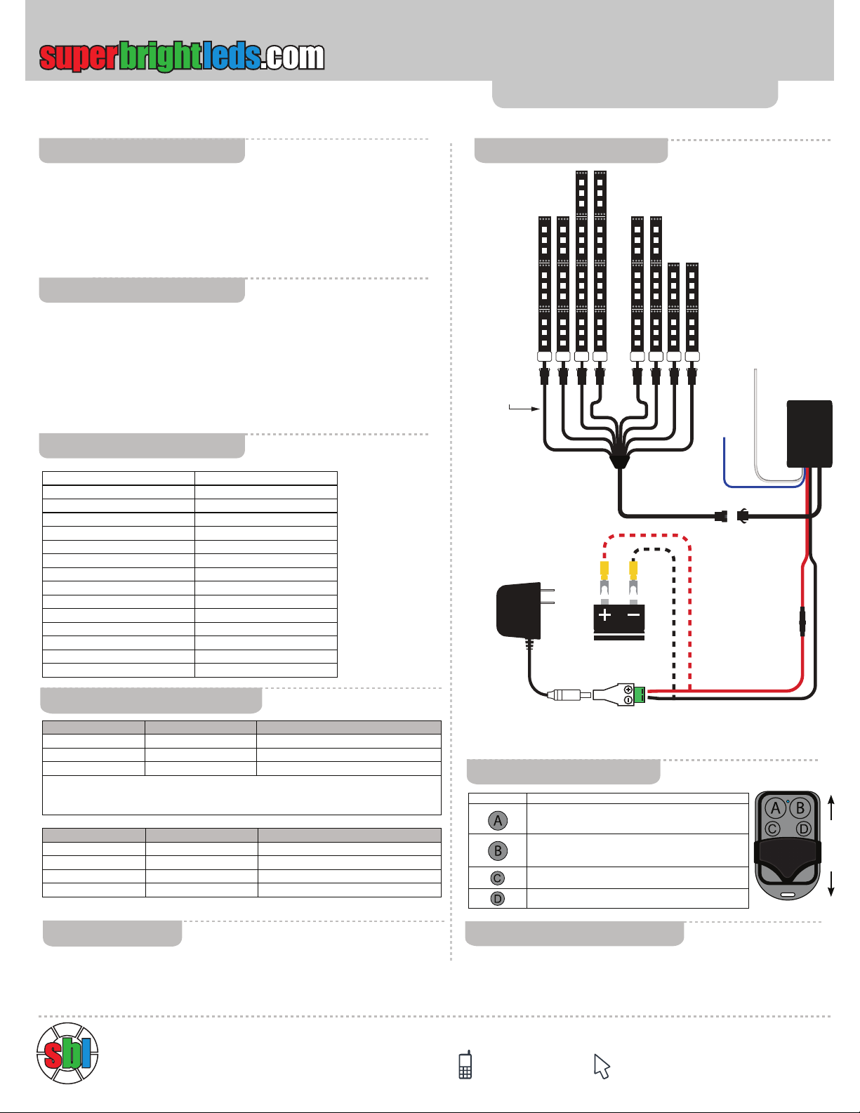
1. Connect strips to Splitter Cable then connect to Controller. Temporarily apply
power to the controller and test strip locations for proper lighting e󰀨ect.
2. Mark the desired location of the strips. Mount strips using double sided tape
or silicone in desired location and away from heat sources and moving parts.
3. Mount controller and connection box in dry locations away from heat sources
and moving parts and route power wires to power source then connect. Route
white antenna wire away from metal objects for maximum operating range.
Multi Color 8 Piece Accent Light Kit
2 - 5” Waterproof Accent Light Strips
4 - 6.75” Waterproof Accent Light Strips
2 - 8.75” Waterproof Accent Light Strips
1 - RF RGB Accent Light Controller
1 - RF Wireless Key Chain Remote (RCW-RFR)
1 - Splitter Cable
1 -12V 27A Battery
Parts Included
Installation
Specications
RGB LED Flexible Light Strip
Battery
1/4” Snap Spades
8-Way Splitter
V+
G
R
B
V+
G
R
B
V+
G
R
B
V+
G
R
B
V+
G
R
B
V+
G
R
B
V+
G
R
B
V+
G
R
B
V+
G
R
B
V+
G
R
B
V+
G
R
B
V+
G
R
B
V+
G
R
B
V+
G
R
B
V+
G
R
B
V+
G
R
B
V+
G
R
B
V+
G
R
B
V+
G
R
B
V+
G
R
B
V+
G
R
B
V+
G
R
B
V+
G
R
B
V+
G
R
B
V+
G
R
B
V+
G
R
B
V+
G
R
B
V+
G
R
B
V+
G
R
B
V+
G
R
B
V+
G
R
B
V+
G
R
B
V+
G
R
B
V+
G
R
B
V+
G
R
B
V+
G
R
B
V+
G
R
B
V+
G
R
B
V+
G
R
B
V+
G
R
B
V+
G
R
B
V+
G
R
B
V+
G
R
B
V+
G
R
B
V+
G
R
B
V+
G
R
B
V+
G
R
B
V+
G
R
B
Power Supply
OR
CPS connector
(CPS-F2ST)
(CPS-12VDC-50W)
Fuse 3A
RGB LED Flexible Light Strip
8-Way Splitter
White
Antenna
Blue
Brake
Override
To Brake
Switch
Controller
RGB RF
Black
Ground
Red
Power In
Blue
Wire
Running Light Cicuit (+)
Ground
White
Antenna
PSC-164
Brake Light
Circuit (+)
V+
G
R
B
V+
G
R
B
V+
G
R
B
V+
G
R
B
V+
G
R
B
V+
G
R
B
V+
G
R
B
V+
G
R
B
V+
G
R
B
V+
G
R
B
V+
G
R
B
V+
G
R
B
V+
G
R
B
V+
G
R
B
V+
G
R
B
V+
G
R
B
V+
G
R
B
V+
G
R
B
V+
G
R
B
V+
G
R
B
V+
G
R
B
V+
G
R
B
V+
G
R
B
V+
G
R
B
V+
G
R
B
V+
G
R
B
V+
G
R
B
V+
G
R
B
V+
G
R
B
V+
G
R
B
V+
G
R
B
V+
G
R
B
V+
G
R
B
V+
G
R
B
V+
G
R
B
V+
G
R
B
V+
G
R
B
V+
G
R
B
V+
G
R
B
V+
G
R
B
V+
G
R
B
V+
G
R
B
V+
G
R
B
V+
G
R
B
V+
G
R
B
V+
G
R
B
V+
G
R
B
V+
G
R
B
Controller
RGB RF
Input Voltage 9~14.8 VDC
Controller Output Current 3 x 1A Maximum
Fuse Size 3A
Operating Temperature -4 ~122° F (-20~50° C)
Strip IP Rating Waterproof IP67
Static Color Dynamic Modes 2
Seven Color Dynamic Modes 2
Static Colors 18
Override Mode 1
Brightness Levels 5
Remote Battery 12V 27A x 1
Remote Range 33 Feet (10m) Maximum
Remote Frequency 315 MHz
FCC ID 2AFXS-JX-R001
Warranty 2 Years
Remote comes paired to the controller. Use the following procedure if additional
remotes are required.On power up, LEDs will be green indicating pairing mode
for three seconds. During green pairing mode, press button “A” then “B” to pair a
new remote.
Remote Pairing
Wiring
Output Connector Polarity Purpose
Black Positive (+) Common Anode
Red Negative (-) Red LED Cathode
Green Negative (-) Green LED Cathode
Blue Negative (-) Blue LED Cathode
Input Wires Polarity Purpose
Black Negative (-) Ground In (-)
Red Positive (+) 9~14.8 VDC Power In (+)
Blue (see below) Positive (+) 9~14.8 VDC Red Override Signal In (+)
Blue wire activates red single color mode at full brightness while voltage is applied.
Use for brake override if required. Works as brake override even when controller is
in standby mode.
Button Functions
Cycles up through 18 single color modes and two 7 color modes.
Press and hold for dimming 80%, 60%, 40%, 20% and back to
100% during single color modes.
Activates Flash Modes during single color modes. Switches
between Flash/Flash/Long Pause and Flash/Flash/Short Pause
during ash modes. Increases cycle speed during 7 color modes
Activates Fading Mode during single color modes. Decreases
cycle speed during 7 color modes.
On/O󰀨
Hold for 6 seconds to return to Mode 1 (Static Red)
RCW-RFR
Slide Cover
Instructional Sheet
Part Number:
4400 Earth City Expy, St. Louis MO 63045 866-590-3533 [email protected]
ALKW8-RGB72
Important: Read all instructions prior to installation.
Multi Color 8 Piece Accent Light Kit
Mode Sequence & Functions
Mode Button A Button B Button C Button D
1 Red Flash Modes Fade Mode On/O󰀨
2 Blue Flash Modes Fade Mode On/O󰀨
3 Light Pink Flash Modes Fade Mode On/O󰀨
4 Green Flash Modes Fade Mode On/O󰀨
5 Gold Flash Modes Fade Mode On/O󰀨
6 Light Blue Flash Modes Fade Mode On/O󰀨
7 Orange Flash Modes Fade Mode On/O󰀨
8 Hot Pink Flash Modes Fade Mode On/O󰀨
9 Light Green Flash Modes Fade Mode On/O󰀨
10 Cool White Flash Modes Fade Mode On/O󰀨
11 Aqua Flash Modes Fade Mode On/O󰀨
12 Pale Rose Flash Modes Fade Mode On/O󰀨
13 Purple Flash Modes Fade Mode On/O󰀨
14 White Flash Modes Fade Mode On/O󰀨
15 Warm White Flash Modes Fade Mode On/O󰀨
16 Sky Blue Flash Modes Fade Mode On/O󰀨
17 Sea Green Flash Modes Fade Mode On/O󰀨
18 Lemon Flash Modes Fade Mode On/O󰀨
19 7 Color Flash Speed Up Speed Down On/O󰀨
20 7 Color Fade Speed Up Speed Down On/O󰀨
FCC Statement
Auxilary Running/Brake Light Example
This device complies with part 15 of the FCC Rules. Operation is subject to
the following two conditions: (1) This device may not cause harmful
interference, and (2) This device must accept any interference received,
including interference that may cause undesired operation. Any changes or
modifications in construction of this device which are not expressly approved
by the party responsible for compliance could void the user’s authority to
operate the equipment.
Note: This equipment has been tested and found to comply with the limits for
a Class B digital device, pursuant to part 15 of the FCC Rules. These limits
are designed to provide reasonable protection against harmful interference in
a residential installation. This equipment generates, uses and can radiate
radio frequency energy and, if not installed and used in accordance with the
instructions, may cause harmful interference to radio communications.
However, there is no guarantee that interference will not occur in a particular
installation. If this equipment does cause harmful interference to radio or
television reception, which can be determined by turning the equipment off
and on, the user is encouraged to try to correct the interference by one or
more of the following measures:
–Reorient or relocate the receiving antenna.
–Increase the separation between equipment and receiver.
–Connect the equipment into an outlet on a circuit different from that to which
the receiver is connected.
–Consult the dealer or an experienced radio/TV technician for help.
Diagram 2
RGB LED Flexible Light Strip
Battery
1/4” Snap Spades
8-Way Splitter
V+
G
R
B
V+
G
R
B
V+
G
R
B
V+
G
R
B
V+
G
R
B
V+
G
R
B
V+
G
R
B
V+
G
R
B
V+
G
R
B
V+
G
R
B
V+
G
R
B
V+
G
R
B
V+
G
R
B
V+
G
R
B
V+
G
R
B
V+
G
R
B
V+
G
R
B
V+
G
R
B
V+
G
R
B
V+
G
R
B
V+
G
R
B
V+
G
R
B
V+
G
R
B
V+
G
R
B
V+
G
R
B
V+
G
R
B
V+
G
R
B
V+
G
R
B
V+
G
R
B
V+
G
R
B
V+
G
R
B
V+
G
R
B
V+
G
R
B
V+
G
R
B
V+
G
R
B
V+
G
R
B
V+
G
R
B
V+
G
R
B
V+
G
R
B
V+
G
R
B
V+
G
R
B
V+
G
R
B
V+
G
R
B
V+
G
R
B
V+
G
R
B
V+
G
R
B
V+
G
R
B
V+
G
R
B
Power Supply
OR
CPS connector
(CPS-F2ST)
(CPS-12VDC-50W)
Fuse 3A
RGB LED Flexible Light Strip
8-Way Splitter
White
Antenna
Blue
Brake
Override
To Brake
Switch
Controller
RGB RF
Black
Ground
Red
Power In
Blue
Wire
Running Light Cicuit (+)
Ground
White
Antenna
PSC-164
Brake Light
Circuit (+)
V+
G
R
B
V+
G
R
B
V+
G
R
B
V+
G
R
B
V+
G
R
B
V+
G
R
B
V+
G
R
B
V+
G
R
B
V+
G
R
B
V+
G
R
B
V+
G
R
B
V+
G
R
B
V+
G
R
B
V+
G
R
B
V+
G
R
B
V+
G
R
B
V+
G
R
B
V+
G
R
B
V+
G
R
B
V+
G
R
B
V+
G
R
B
V+
G
R
B
V+
G
R
B
V+
G
R
B
V+
G
R
B
V+
G
R
B
V+
G
R
B
V+
G
R
B
V+
G
R
B
V+
G
R
B
V+
G
R
B
V+
G
R
B
V+
G
R
B
V+
G
R
B
V+
G
R
B
V+
G
R
B
V+
G
R
B
V+
G
R
B
V+
G
R
B
V+
G
R
B
V+
G
R
B
V+
G
R
B
V+
G
R
B
V+
G
R
B
V+
G
R
B
V+
G
R
B
V+
G
R
B
V+
G
R
B
Controller
RGB RF
Tip: To use RGB LED light strips for auxilary
running lights/brake lights, set controller for red
color and dim to 40% or 20% to simulate parking
lights. Attach Blue wire from controller to the
positive brake light wire on the motorcycle. After
pairing mode the LED light strips will be dim red
when controller is on and the LED light strips
will be full brightness red when brake is applied.
Controller will activate full brightness red mode
anytime the controller is powered and a positive
signal is applied to the blue wire. Strips will now
function as auxiliary Tail/Brake lights to enhance
visibility and safety.

Other superbrightleds Lighting Equipment manuals

superbrightleds XS-RG User manual

superbrightleds

superbrightleds XS-RG User manual

superbrightleds STN-1-TW User manual

superbrightleds

superbrightleds STN-1-TW User manual

superbrightleds NFLSK-W600-VCT User manual

superbrightleds

superbrightleds NFLSK-W600-VCT User manual

superbrightleds NDC2K-RGB150 User manual

superbrightleds

superbrightleds NDC2K-RGB150 User manual

superbrightleds FLD-CNL-60005-100W User manual

superbrightleds

superbrightleds FLD-CNL-60005-100W User manual

superbrightleds MWPE Series User manual

superbrightleds

superbrightleds MWPE Series User manual

superbrightleds USP Series User manual

superbrightleds

superbrightleds USP Series User manual

superbrightleds RWLA Series User manual

superbrightleds

superbrightleds RWLA Series User manual

superbrightleds STN-2-TW User manual

superbrightleds

superbrightleds STN-2-TW User manual

superbrightleds User Manual User manual

superbrightleds

superbrightleds User Manual User manual

superbrightleds EL-RW User manual

superbrightleds

superbrightleds EL-RW User manual

superbrightleds FUT Series User manual

superbrightleds

superbrightleds FUT Series User manual

superbrightleds STN-1-RGB User manual

superbrightleds

superbrightleds STN-1-RGB User manual

superbrightleds WPFC2 Series User manual

superbrightleds

superbrightleds WPFC2 Series User manual

superbrightleds ALKW9-RGB93 User manual

superbrightleds

superbrightleds ALKW9-RGB93 User manual

superbrightleds EL3-RW User manual

superbrightleds

superbrightleds EL3-RW User manual

superbrightleds HLV8 Series User manual

superbrightleds

superbrightleds HLV8 Series User manual

superbrightleds LPD Series User manual

superbrightleds

superbrightleds LPD Series User manual

superbrightleds LPL-RGB9WR User manual

superbrightleds

superbrightleds LPL-RGB9WR User manual

superbrightleds MWP2-SW Series User manual

superbrightleds

superbrightleds MWP2-SW Series User manual

superbrightleds EL2-RW User manual

superbrightleds

superbrightleds EL2-RW User manual

superbrightleds FLD-CNL-60005-150W User manual

superbrightleds

superbrightleds FLD-CNL-60005-150W User manual

superbrightleds WPGL2 Series User manual

superbrightleds

superbrightleds WPGL2 Series User manual

superbrightleds RSL Series User manual

superbrightleds

superbrightleds RSL Series User manual

Popular Lighting Equipment manuals by other brands

CAME DADOO quick guide

CAME

CAME DADOO quick guide

SGM P Series user manual

SGM

SGM P Series user manual

JUSK PONTUS 4911745/72213001 manual

JUSK

JUSK PONTUS 4911745/72213001 manual

Orno OR-PL-6092WLPMR4 Operating	 instruction

Orno

Orno OR-PL-6092WLPMR4 Operating instruction

EuroLite LED KLS-120 FX user manual

EuroLite

EuroLite LED KLS-120 FX user manual

Stahl 6091/2 Series operating instructions

Stahl

Stahl 6091/2 Series operating instructions

Equinox Systems Saturn Spot user manual

Equinox Systems

Equinox Systems Saturn Spot user manual

Channel MCT instruction manual

Channel

Channel MCT instruction manual

SSLUCE SF1205WE1TB-18 user manual

SSLUCE

SSLUCE SF1205WE1TB-18 user manual

EuroLite LED DMX Pixel Tube 16 RGB IP20 user manual

EuroLite

EuroLite LED DMX Pixel Tube 16 RGB IP20 user manual

Philips CZS102 user manual

Philips

Philips CZS102 user manual

Goobay 60340 user manual

Goobay

Goobay 60340 user manual

QNect QN-WLS01 manual

QNect

QNect QN-WLS01 manual

KSE-LIGHTS KS-7650 manual

KSE-LIGHTS

KSE-LIGHTS KS-7650 manual

Lightolier DPB2S18DS340 Specification sheet

Lightolier

Lightolier DPB2S18DS340 Specification sheet

Stoane Lighting inter-lux Niche Installation and maintenance instructions

Stoane Lighting

Stoane Lighting inter-lux Niche Installation and maintenance instructions

ARRI M18 Service manual

ARRI

ARRI M18 Service manual

Light Sky TourPro s500 Hybrid user manual

Light Sky

Light Sky TourPro s500 Hybrid user manual

manuals.online logo
manuals.online logoBrands
  • About & Mission
  • Contact us
  • Privacy Policy
  • Terms and Conditions

Copyright 2025 Manuals.Online. All Rights Reserved.