Předepsané utahovací momenty:
:
M5 5,9 Nm 6,5 Nm
M6 10.0 Nm 10,5 Nm
M10 49,0 Nm 51,0 Nm
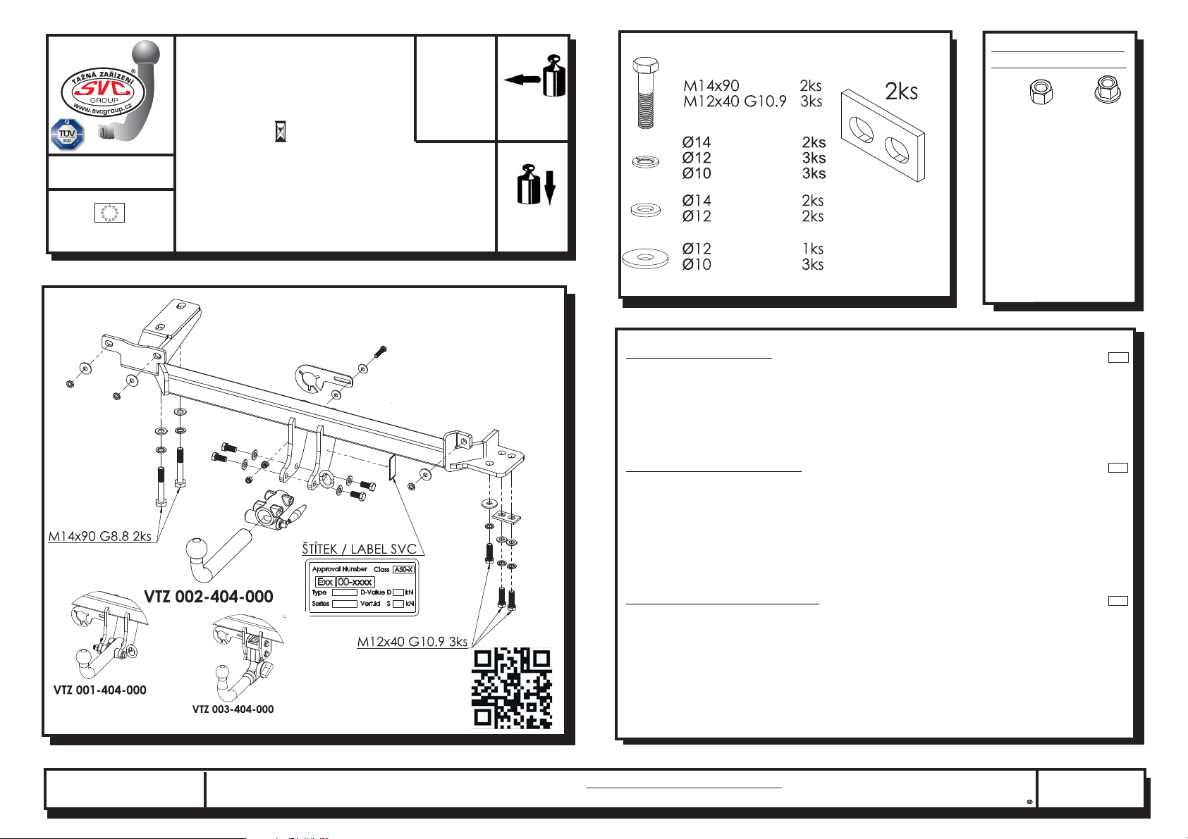
M12 85,0 Nm 87,0 Nm
M14 135,0 Nm 138,0 Nm
M16 210,0 Nm 214.1 Nm
Specified torque settings
SVC GROUP s.r.o.
Průmyslová zóna - 179
547 01 Náchod-ČR
INFO: www.svcgroup.cz
Tel.:+420 491421021
mob.: +420 603360607
01/15 SVC NROUP
N1/5
D
GB
Všeobecné pokyny, též viz. typový list:
General instructions, also see Type certificate:
Allgemeine Anweisungen siehe auch Typenschein:
-
-
Montáž tažného zařízení a el instalace, musí odpovídat požadavku výrobce vozu a příslušného státu kde se výrobek používá.
Při případném výřezu nárazníku, výrobce tažného zařízení provedl zkoušky na vozidle se standardním nárazníkem na počátku
výroby vozidla a neručí za informace k výřezu při případné změně či faceliftu vozu či nárazník.
1. V úchytech a spojích tažného zařízení s karosérii musí být karosérie očištěna od měkkých antikorozních ochran nástřiku
karosérie. Všechny vrtané otvory očistěte od špon a ošetřete antikorozním přípravkem.
2. Používejte dodaný pevnostní spojovací materiál.
3. Kulový čep nesmí ze zákona překrývat registrační značku vozu, pokud není připojen přívěsný vozík..
4. Zapojení el. instalace tažného zařízení k vozu musí odpovídat příslušným platnýmnormám a požadavkům výrobce vozu
(viz. příručka k vozu, či u prodejce vozu). Tažné zařízení je pevnostně zkoušeno a homologováno dle předpisu EHK 55 a splňuje
tuto normu ES.
The towing device assembly and electric installation must comply with the requirements of the car producer and the particular state
where the product is used.
- The coupling device manufacturer has carried out some tests on a car with a standard bumper which was used at the beginning
of making a car and so the manufacturer is not liable for information about a posssible slot in a bumper in case of changes or a
facelift of a car during a car production.
1. Clean a car body from soft anticorrosive protection of a car body coat in brackets and joints of a coupling device with a car body.
Clean all drilled holes from metalshavings and treat them with antirust agent.
2. Use supplied strength joining material.
3. A ball pin, according to a law, cannot cover a number plate, if a trailer is not joined.
4. Wiring of a coupling device must be up to a standard and car maker requirements. (see a car manual or ask a car seller).
5. The coupling device has been physically tested and homologated according to the regulation EHK55 and is up to the EC
standard.
- Die Montage der Anhängerkupplung sowie die Elektroinstallation muss den Anforderungen des Fahrzeugherstellers in dem Staat
entsprechen, in welchem das Produkt benutzt wird.
- be1i einem allfälligen Ausschneiden der Stoss- Stange der Hersteller der Zugsvorrichtung führte Proben an Wagen mit gängigen
Stoss- Stangen am Anfang der Wagenherstellung durch und haftet keinesfalls für Informationen bezüglich des Ausschneidens
sowie für allfällige Änderungen oder face- Liftings des Wagens oder der Stoss- Stange.
1. Bei den Aufhängungen und Verbindungen der Zugsvorrichtung mit der Karosserie muss dieselbe von weichen Rostschutzmitteln
gereinigt werden. Reinigen Sie sämtliche gebohrte Öffnungen von Spänen und behandeln diese mit einem Rostschutzmittel.
2. Benützen Sie das gelieferte Festigkeits- Verbindungsmaterial.
3. Der Kugelbolzen darf von Gesetzes wegen nicht das Kennzeichen des Wagens verdecken, sofern kein Anhänger an den Wagen
angehängt ist.
4. Der Anschluss der Elektroinstallation der Zugsvorrichtung an den Wagen muss den entsprechenden gültigen Normen und
Anforderungen des Wagenherstellers entsprechen (siehe Handbuch zum Wagen,oder beim Verkäufer des Wagens).
Die Zugsvorrichtung wurde in Bezug auf die Festigkeit nach der Vorschrift EHK 55geprüft und genehmigt und erfüllt die ES- Norm.
-
CZ
TYPE:
VTZ 001/2/3-404
D
Hodnota
Wert
value
Typ/Type VTZ 001-404
002-404
VTZ 003-404
VTZ
2100 kg
10,70 kN
Montážní návod
Fitting instruction
Montageanleitung
RANGE ROVER EVOQUE
06/2011->
EHK 55 e94/20
Classe A50-X
130 kg
E27 55R 01-0278
xxx
VT-20 /6014


