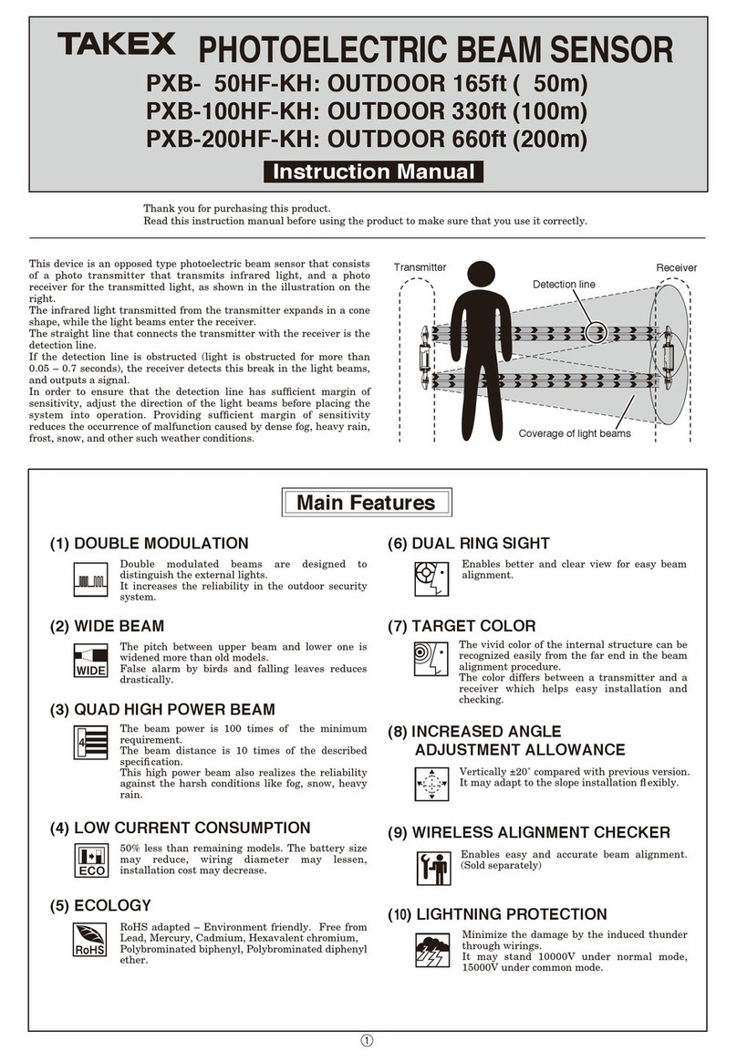
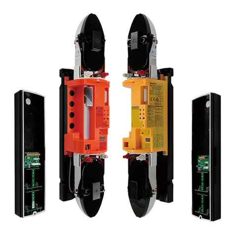
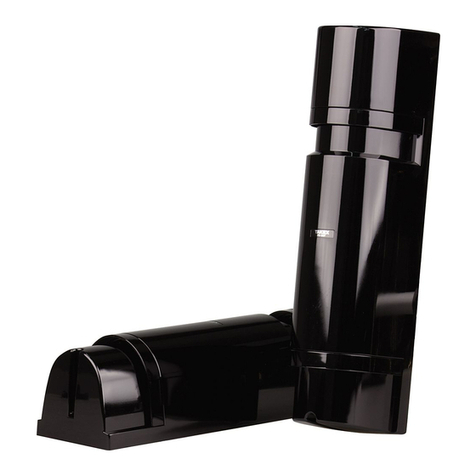
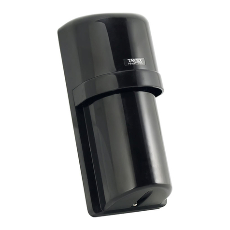
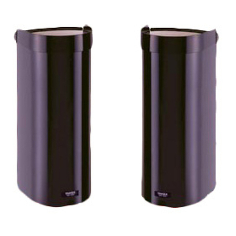
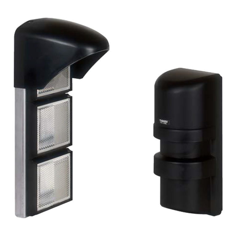
Takex PXB-100ATC User manual

(9) DRIP-PROOF HOUSING
Prevents rain and snow from streaming down
the front side of housing, helping to avoid false
alarm.
Main Features
Coverage of light beams
Upper detection line
Lower detection line
Receiver
Transmitter
Keeps birds and small animals away from the
sensor, helping to reduce false alarms.
The vivid color of the internal structure can be
recognized easily from the far end in the beam
alignment procedure.
The color differs between a transmitter and a
receiver which helps easy installation and
checking.
Enables easy and accurate beam alignment.
(Sold separately)
Minimizes the damage caused by induced
lightning through wiring.
Vertically ±20°compared with previous version.
It may adapt to the slope installation exibly
Enables better and clear view for easy beam
alignment.
Double modulated beams are designed to distinguish the true
beam signal from accidental or deliberate interference from
sunlight, car headlights and other articial light sources.
This increases the reliability in the outdoor security system.
The beam power is 100 times of the minimum requirement.
The beam distance is 10 times of the described specication.
This high power beam also realizes the reliability against the
harsh conditions like fog, snow, heavy rain.
IP65 rated, with anti-insect bushing and special wading.
Thank you for purchasing this product.
Read this instruction manual before using the product to make sure that you use it correctly.
&HF
AT
Upper and lower beam individually detects the objects and
issues a signal only by blocking each beam.
AT output : OR-gated by upper and lower beam.
HF output : AND-gated.
By synchronizing the timing of transmitting and receiving
beam, the stacking system will be more reliable.
PHOTOELECTRIC BEAM SENSOR
Instruction Manual
(1) ANTI-CRAWL DETECTION
(2) AT . HF SEPARATE OUTPUT
1
2
3
4
(3) SYNCHRONIZED HIGH POWER BEAM
(5) QUAD HIGH POWER BEAM
(6) ECOLOGY
(7) INSECT/WATER PREVENT
(8) ANTI-BIRD STOPPER
(10)
DUAL RING SIGHT
(11)
TARGET COLOR
(12)
INCREASED RANGE
ADJUSTMENT ALLOWANCE
(13)
WIRELESS ALIGNMENT CHECKER
(14)
LIGHTNING PROTECTION
(4) DOUBLE MODULATION
RoHS adapted - Environment friendly. Free from Lead,
Mercury, Cadmium, Hexavalent chromium, Polybrominated
biphenyl, Polybrominated diphenyl ether.
Anti-Crawl and Anti-Corrosion
PXB-100ATC : OUTDOOR 330ft (100m)
This device is an opposed type photoelectric beam sensor that consists of
a photo transmitter that transmits infrared light, and a photo receiver
for the transmitted light, as shown in the illustration on the right.
The infrared light transmitted from the transmitter expands in a cone
shape, while the light beams enter the receiver.
The straight line that connects the transmitter with the receiver is the
detection line.
This model is designed to prevent a crawling intrusion to coverage area
by means of OR-gated detection in addition to AND-gated detection.
In order to ensure that the detection line has sufcient margin of
sensitivity, adjust the direction of the light beams before placing the
system into operation. Providing sufcient margin of sensitivity reduces
the occurrence of malfunction caused by dense fog, heavy rain, frost,
snow, and other such weather conditions.
1

Check that the following transmitter, receiver, and accessories are included in the box when you first
unpack the product.
View finder
Reflector
Horizontal angle fine
adjustment screw (White)
Vertical angle
adjustment screw (Red)
Wiring terminal
Cover Detect switch (Detects
opening/closing of the cover)
Cover
Swivel base (White)
(Horizontal angle
adjustment)
Cut bush
Installation plate : 2 pcs
Pole cover
Knockout
(2 places at
top and
bottom)
Sensor body : 2 pcs (Transmitter: 1 pc, Receiver: 1 pc)
Sensor fixing screw
: 2 point
Pole cover
fixing screws
Cover locking screw
Grommet
Swing arm (Red)
(Vertical angle adjustment)
Caution: Do not peel off or damage
the waterproof film.
Waterproof film
Upper optical unit
Lower optical unit
TRANSMITTER
RECEIVER
Transmitter/Receiver label on rear surface
Mold color
Fluorescent yellow:
Transmitter
Fluorescent orange:
Receiver
Function setting section
explained in
1-3 NAME OF OPERATION
SETTING
Optional
: 2pcs
: 2 pcs
Pole installation fitting
: 4 pcs
(compatible with single tube)
Cable tie
: 8 pcs
Bird stopper
: 4 pcs
Instruction Manual
(This Manual)
: 1 pc
Self-tapping screw
for installation
(φ4×30mm)
: 8 pcs
Countersunk
oval-head screw
(M4×20mm)
: 8 pcs
8
OPERATION CHECK
9 EXPLANATION OF FUNCTIONS
9-1
9-2
9-3
9-4
9-5
9-6
9-7
9-8
10
11
12
13
TROUBLESHOOTING
SPECIFICATIONS
EXTERNAL DIMENSIONS
OPTIONAL
PRODUCT COMPONENTS
1-1
1-2
1-3
OPERATING PRECAUTIONS
2-1
BEFORE USE
3-1
3-2
3-3
3-4
3-5
INSTALLATION METHOD
4-1
4-2
INITIAL SETTING
5-1
5-2
5-3
5-4
5-5
5-6
5-7
5-8
1
2
3
4
5
PARTS DESCRIPTION
ACCESSORIES
NAMES OF OPERATION SECTION
EXAMPLE OF INCORRECT INSTALLATION
PROTECTION DISTANCE AND RANGE OF LIGHT
BEAM COVERAGE
MOUNTING HEIGHT
OPTICAL AXIS ADJUSTMENT RANGE
TERM DESCRIPTION
APPLICATIONS
WALL INSTALLATION METHOD
POLE INSTALLATION METHOD
MODULATION FREQUENCY CHANGEOVER
SYNCHRONIZED TIMING
MASTER / SLAVE SELECTION
BEAM POWER SELECTION
ALARM OUTPUT SWITCH
ENVIRONMENTAL OUTPUT SWITCH
RESPONSE TIME
SOUND CHECK
......................................................
.................................................................
..................................
.....................
...........................................................
.........................................................
.............................
.......................................................
...............................................................
........................................
........................................
..................
.................................................
.........................................
.............................................
................................................
..............................
.............................................................
................................................................
2
2
3
4
5
5
5
6
6
9
10
11
11
11
11
11
11
12
12
6 WIRING METHOD
6-1
6-2
6-3
POSITION AND RATING OF TERMINALS
WIRING DISTANCE
WIRING DISTRIBUTION DIAGRAM (WIRING DIAGRAM)
NAMES AND FUNCTIONS OF OPTICAL AXIS
ADJUSTMENT PARTS
OPTICAL AXIS ADJUSTMENT USING
THE ALIGNMENT MECHANISM
AUTO GAIN LOCK FUNCTION
UPPER / LOWER CHANGEOVER FUNCTION
PROGRAMMABLE AGC FUNCTION
EXTERNAL ENVIRONMENT DIAGNOSTIC FUNCTION
ALARM LED
LIGHT SENSITIVITY SIGNAL FUNCTION
FUNCTION SETTING CHECK
ALIGNMENT WIRELESS CHECKER CONNECTION
FUNCTION
12
13
13
............................
...............................................................
...
...........................................................
............................................
......................................................................
..............................................
.....................
.....................................
...........
............................................................................
............................
...............................................
.............................................................................
.....................................................................
..........................................................................
.............................................................
......................................................................................
7 OPTICAL AXIS ADJUSTMENT
7-1
15
16
20
21
21
22
22
22
22
22
22
23
23
24
24
7-2
1-1 PARTS DESCRIPTION
1-2 Accessories
—TABLE OF CONTENTS —
1PRODUCT COMPONENTS This section describes the contents of the product package and the names and functions of
the parts that appear in this instruction manual.
2

[Transmitter]
[Receiver]
NAMES OF OPERATION SECTION
1-3
“5 INITIAL SETTING (5-4 BEAM POWER SELECTION )”
“5 INITIAL SETTING (5-1 MODULATION FREQUENCY CHANGEOVER)”
“9 EXPLANATION OF FUNCTIONS (9-1 AUTO GAIN LOCK FUNCTION)”
“5 INITIAL SETTING (5-8 SOUND CHECK)”
“5 INITIAL SETTING (5-7 RESPONSE TIME)”
“5 INITIAL SETTING (5-6 ENVIRONMENTAL OUTPUT SWITCH)”
“5 INITIAL SETTING (5-5 ALARM OUTPUT SWITCH)”
“5 INITIAL SETTING (5-3 MASTER/SLAVE SELECTION)”
“5 INITIAL SETTING (5-2 SYNCHRONIZED TIMING)”
“9 EXPLANATION OF FUNCTIONS
(9-2 UPPER/LOWER CHANGEOVER FUNCTION)”
“9 EXPLANATION OF FUNCTIONS
(9-2 UPPER/LOWER CHANGEOVER FUNCTION)”
Transmission LED
(Upper/lower)
Light reception authorization LED
(Upper/lower) : Red
Beam power switch (Factory set : H)
Transmitter channel changeover swicth (Factory set : 1CH)
Alarm LED : Red
Sensitivity attenuation LED : Red
Sound check switch (Factory set : OFF)
Auto-gain lock switch
(Factory set : OFF)
Monitor Jack
Receiver channel changeover switch (Factory set : 1CH)
Upper/Lower changeover switch
Upper/lower changeover switch
Synchronized timing switch (Factory set : A)
Environmental output switch (Factory set : N.C.)
Alarm output switch (Factory set : N.C.)
Detection response time adjustment switch (Factory set : 0.1sec)
Master/Slave selection switch (Factory set : Master)
Vacant6,7,8.
5.
4.
3.
1,2.
8.
6,7.
5.
4.
3.
1,2.
Please set "ON" after complete optical axis adjustment.
Cover Detect Switch
Cover Detect Switch
3

Do not use the sensors powered with a voltage level other than
the indicated power supply voltage specied (between 10 to
30V DC). Doing so may cause a re or electrical shock.
Do not connect a device that exceeds the capacity shown to the
output contact of this device. Doing so may cause a re or
electrical shock.
Do not touch the terminal section with wet hands.
Doing so may cause an electrical shock.
Do not disassemble or modify this device. Doing so may cause
a re, electrical shock, or malfunction of the device.
If smoke or an abnormal odor or sound is found, leaving it
unattended may cause a re or electrical shock. Immediately
turn off the power to the device and conrm that the
abnormal state has been corrected, and then ask the place of
purchase for repair.
EXAMPLE OF INCORRECT INSTALLATION
2-1 DON'TS Do not install as shown below. This will cause
erroneous detection or detection failure.
Installation in locations
shaded by trees etc.
Installation on uneven
ground
Slanted installation Overhead wiring Horizontal installation Installation close to a wall
Installation in locations where the
unit may be splashed by dirty
water or direct sea spray
Installation directly above
a wall
Installation in an
unstable, wobbling location
Installation in location where
strong light such as sunlight or
light from vehicle headlights can
directly enter the receiver
Installation in areas where
objects that move with the
wind (the laundry etc) can
obstruct the optical axis
Using PXB-100ATC
together with other models
(Except PBX-100HF)
2OPERATING PRECAUTIONS This manual describes the precautions to be observed for safe operation of this
device by classifying them into the following categories. As these are important, be
sure to read and strictly observe them.
Warning
Caution
Description of the Display
Indicates information that if ignored and the device is handled incorrectly, may result in death or serious injury.
Indicates information that if ignored and the device is handled incorrectly, may result in injury or damage to property alone.
This symbol indicates a prohibited action, with the specic action shown near the symbol.
Indicates the useful information.
Example: Do not disassemble
Warning
Caution
(1) When using multi-level protection, use sensors of the same model for both upper and lower sensors, and set the
same transmission power (H/L) for all of them.
(2) Using these sensors together with sensors from a different series (e.g. PB-IN-HF) may cause interference between
the sensors.
Do not install this device in a location that cannot support its
weight. Doing so may cause the device to fall and cause an
injury or malfunction of the device.
1. In areas where there are trees or weeds, the infrared may get obstructed by overgrown branches or leaves.
As this may cause erroneous detection, be sure to trim down leaves and branches according to the growth of the plants.
Furthermore, the infrared may get obstructed by swaying branches or leaves due to wind. Keep in mind the swaying of leaves and
branches when trimming them.
2. Vine type plants may wrap around the photoelectric beam sensors causing erroneous detections. Therefore, be sure to prune such plants
regularly.
3. Other natural phenomena such as insects or bird droppings may soil the sensors causing miss detection. Be sure to clean the sensors
regularly.
Cautions when using the outdoor photoelectric beam sensor (Daily maintenance)
4
3
PROTECTION DISTANCE AND
RANGE OF LIGHT BEAM COVERAGE
3-1 As the infrared light leaves the transmitter, it expands into conic shape light beams.
The optical axis is in the center of the light beams. Arrange the reflector so that the
device on the opposite side is in the center of the light beams.
MOUNTING HEIGHT
3-2
OPTICAL AXIS ADJUSTMENT RANGE
3-3
As these sensors are designed to detect humans, install so that the center of the sensors are at a height of
approximately 2.6ft (0.8m) from the ground when installing both on a wall and on a pole.
BEFORE USE In order to use these sensors correctly, thoroughly read this instruction manual and select the mounting position and
protection distance.
If the optical axis is not aligned correctly, there will be
insufcient margin of sensitivity even if the receiver is
at the center of the light beams, making the system
more susceptible to adverse effects of the environment
resulting in a malfunction.
If the optical axis (center of the light beams) is aligned
correctly, a detection line with sufcient margin of
sensitivity is formed.
(180°)
+90°
-
90°
(40°)
(40°)
+20°
-
20°
+20°
-
20°
Top View
Stacking :
Side view
1ft(0.3m)
1ft(0.3m)
Standard setting
In order to prevent the intrusion by crawling or climbing over, stack PXB-100ATC in several numbers.
Set the sensor about 1ft(0.30m) from the
oor so that it will detect the head of
crawling person.
To prevent a intruder from climbing over
the standard setting beams, set the sensor
at the height upper than standard setting.
4.45" (113mm)
4.45" (113mm)
7.24" (184mm)
Approx. 2.6'(0.8m)
Installing so that the center of the sensor is
approximately 2.6ft (0.8m) from the ground means that
the protection line is at waist height for humans,
enabling reliable detection.
If the installation position is too high or too low, the
protection line will be above shoulder height or below
knee height, making it more difcult for reliable
detection.
CORRECT
CORRECT
WRONG
WRONG
WRONG
CORRECT
WRONG
Maximum 330ft (100m)
8ft(2.4m)
5

APPLICATIONS
3-5
Connect the synchronized units by wire
Set the transmitter and receiver to the same channel
Set the transmitter as a master
Set the transmitter and receiver to the same syncronized timing
D
A
B
C
Single stacking
Single stacking
* Synchronized wire is necessary for even single stacking.
* Please note that there is an electric polarity in a synchronized wire.
Transmitter Receiver
12345678
D
Synchro
input
(polarity)
Synchro
output
(polarity)
2
3
4
1
Connect between synchronized units
2
3
1
Set as Master
12345678
Set as A timing
Set as 1CH
Set as A timing
Set as 1CH
Synchro
input
(polarity)
C
B
A
B
A
TERM DESCRIPTION This manual uses the following terms for explanation. Refer to the terms and their meanings.
3-4
: Frequency channel of the infrared beam signal. (There are four channel from 1CH to 4CH)
: A signal emitted from the synchronized output of the master, which is the reference signal to
determine the timing for transmitting and receiving the infrared beams.
: A device to output the synchronized signal, which is used as a reference to determine the timing
for transmitting and receiving the infrared beams. (Only the transmitter can be set as the master.)
: A device to transmit or receive the infrared beams based on the input synchronized signal.
(The receiver operates as the slave.)
: Timing for transmitting and receiving the infrared beams based on the synchronized signal.
You can select from two types of timing, A and B.
Change the synchronized timing in the same channel to achieve the multi-level protection.
: A wire to transfer the synchronized signal from the master to the slaves.
Channel (CH)
Synchronized signal
Master
Slave
Synchronized timing
Synchronized wire
6

D
A
B
C
H
I
E
F
G
2 level stackings
Transmitter Receiver
12345678
D
2
3
4
12
3
1
Set as a master
Receiver
12345678
2
3
4
1
12345678
1st beam setting (Same as single stacking)
2nd beam setting
Set the transmitter and receiver to the same channel as 1st beam
Set the transmitter and receiver to the different syncronized timing from 1st beam
Set the transmitter as a slave
Connect the syncronized units by wire
Set the transmitter and receiver to the same channel
Set the transmitter and receiver to the same syncronized timing
Set the transmitter as a master
Connect the synchronized units by wire
Connect between synchronized unit
Set as A timing
Set as 1CH
Set as A timing
Set as 1CH
Connect between synchronized unit
Transmitter
Connect between syncronized unit
Set as Slave
Set as B timing
Set as 1CH
* Please note that there is an electric polarity in a synchronized wire.
Synchro
output
(polarity)
Synchro
input
(polarity)
Synchro
Synchro
input
output
(polarity)
(polarity)
Synchro
input
(polarity)
Synchro
input
(polarity)
2 Level Stacking Application
A
B
A
B
C
HI
EE
FF
G
12345678
1
s
t
2
n
d
2
3
1
Set as B timing
Set as 1CH
7

Transmitter Transmitter
Transmitter
Transmitter
Transmitter
Transmitter Receiver Transmitter Receiver
Receiver
Receiver
Receiver Receiver
Transmitter Receiver
Receiver
Transmitter
Transmitter
Receiver
Transmitter
Transmitter
Receiver
Receiver
Synchro
Synchro
Sybnchro
Synchro
Synchro
Synchronized wiring
Synchronized
wiring
3CH
A
Slave
1CH
B
Slave
1CH
A
Master
3CH
B
Slave
1CH
A
3CH
B
1CH
B
3CH
A
3CH
A
Slave
3CH
A
1CH
B
Slave
1CH
B
Transmitter Receiver
1CH
A
Master
1CH
A
1CH
1CH
A
Master
B
Slave
s
1
t
2
n
d
1CH
1CH
A
B
1
s
t
2
n
d
1CH
1CH
A
Master
B
Slave
1
s
t
2
n
d
4CH
4CH
A
Master
B
Slave
1
s
t
2
n
d
This product adopts the synchronized wire system to allow up to two units having the same channel to be installed in the same
direction. If the modulating beam frequency switch function is used together, up to two spans for 6 or 8 level stacking line
protection, four spans for the 4-level stacking line protection, eight spans for the 2-level stacking line protection can be easily
installed.
3CH
3CH
A
Slave
B
Slave
1
s
t
2
n
d
2CH
2CH
A
Slave
B
Slave
1
s
t
2
n
d
2CH
2CH
A
B
1
s
t
2
n
d
4CH
4CH
A
B
1
s
t
2
n
d
3CH
3CH
A
B
1
s
t
2
n
d
3CH
3CH
A
Slave
B
Slave
1
s
t
2
n
d
3CH
3CH
A
B
1
s
t
2
n
d
Transmitter
1CH 1CH
A
A
B
B
A
A
Master
s
11
t
Receiver
s
t
Transmitter
Slave
n
d
Receiver
n
d
Transmitter
3CH
Slave
r
d
Receiver
3CH
r
d
Not neighboring channel
(1CH and 3CH)
(2CH and 4CH)
Transmitter Receiver
Synchro
Not neighboring channel
(1CH and 3CH)
(2CH and 4CH)
Synchro
A
1CH
1
s
t
1CH
A
Master
s
t
1
1CH
B
Slave
2
n
d
3CH
A
Slave
3
r
d
3CH
B
Slave
t
h
3CH
B
t
h
3CH
A
3
4
4
r
d
1CH
B
2
n
d
1
s
t
2
n
d
1CH
1CH
A
B
Triple level stacking
Straight line protection
2 level straight line protection (Maximum : Eight spans) 2 level external perimeter protection
Perimeter round protection
Fourth level stacking (Maximum : Four spans)
Avoid setting the neighboring number of channel
in the same direction. (Like 1CH and 2 CH)
Avoid setting the neighboring number of channel
in the same direction. (Like 1CH and 2 CH)
In the 3rd and 4th beam, set the same channel
and different synchronized timing.
Receiver
1CH 1CH
22
33
8

15 mm
Marking
Label
1
WALL INSTALLATION METHOD
4-1
t-PPTFOUIFDPWFSĀYJOHTDSFXBOESFNPWFUIFDPWFS
t-PPTFOUIFTFOTPSĀYJOHTDSFXTQDTBOESFNPWFUIF
TFOTPSCPEZ
5IJTXPSLJTSFRVJSFEBTBOJOTFDUQSPPGBOEEVTUQSPPG
DPVOUFSNFBTVSFGPSUIFTFOTPSFYUFSJPS
/PUF*GUIFSFJTBHBQCFUXFFOUIFXJSFBOEUIF
DVUCVTIVTFUIFDBCMFUJFJODMVEFEUP
UJHIUFOBOEDMPTFUIFHBQ
5IJTXPSLJTSFRVJSFEBTBOJOTFDUQSPPGBOEESJQQSPPGDPVOUFSNFBTVSF
GPSUIFTFOTPSFYUFSJPS
2
3
5
4
6
Installation plate
Cover
Installation
plate
Self-tapping screw
for installation
(Ø4x30)
Note: Accessories
Grommet
About the grommet
t
3FGFSUPTFDUJPO6 WIRING METHOD UPDPOOFDUUIFXJSJOH
3FGFSUPTFDUJPO5 INITIAL SETTING UPUIFGVODUJPOTTFUUJOH
3FGFSUPTFDUJPO7 OPTICAL AXIS ADJUSTMENT
UPBEKVTUUIFPQUJDBMBYJT
Bird stopper
(Accessory)
Knockout
0.39"(10 mm)
0.39"(10 mm)
1.77"(45 mm)
1.38"(35 mm) 9.45"(240 mm)
3.29"(83.5 mm)
t5SJNEPXOUIFEJBNFUFSPGUIFDVUCVTITPUIBUJUJTUPB
EJBNFUFSTNBMMFSUIBOUIBUPGUIFEJBNFUFSPGUIFXJSJOH
t1BTTUIFXJSJOHUISPVHIUIFDVUCVTI
t6TFUIFTFOTPSĀYJOHTDSFXTQDTUPĀYUIFTFOTPSCPEZUP
UIFJOTUBMMBUJPOQMBUF
t1MBDFUIFJOTUBMMBUJPOQMBUFJOQPTJUJPOUIFOFOTVSFUIBUUIF
TQBDFTIPXOCZUIFEPUUFEMJOFTJTBMMPDBUFECFGPSFNBSLJOH
UIFQPTJUJPOTPGUIFTDSFXT
/PUF'PSXJSJOHXJUIBOFYUFSOBMEJBNFUFSPGNN
UPNNCSFBLUIFNFNCSBOFCZQSFTTJOHJU
UISPVHIUIFSFDFTT
/PUF'PSXJSJOHXJUIBOFYUFSOBMEJBNFUFS
FYDFFEJOHNNDVUPGGUIF
TFDUJPOTIPXOCZUIFEPUUFEMJOFTJOUIF
ESBXJOHCFMPXVTJOHOJQQFSTPSFRVJWBMFOU
UPPMT#FTVSFUPDBVMLUIFDVUTFDUJPOBTBO
JOTFDUQSPPGDPVOUFSNFBTVSF
When installing using
the same installation
holes as those for the
PB-F/PB-IN-HF series
When installing in the
switch box.
t6TFUIFJOTUBMMBUJPO
IPMFTPGQJUDI
NN
t"UUBDIUIFDPWFSUPUIFTFOTPSCPEZBOEĀYJUJOQMBDFVTJOH
UIFDPWFSĀYJOHTDSFXT
t"UUBDICJSETUPQQFSTUPUIFDPWFSBTBOEXIFOOFFEFE
/PUF8IFOQFSGPSNJOH
FYQPTFEXJSJOHDVU
UIFLOPDLPVUBUUIF
CPUUPNPGUIFDPWFS
VTJOHXJSFOJQQFSTPS
FRVJWBMFOUUPPMTBOE
DPOOFDUXJSJOH
INSTALLATION METHOD
4
Cover fixing screw
Sensor body
Sensor fixing screw
t5JHIUFOUIFTFMGUBQQJOHTDSFXTGPSJOTUBMMBUJPOQDTJOUIF
NBSLJOHMPDBUJPOTVQUPNNPGUIFTDSFXCPEZ
t1BTTUIFXJSJOHNBUFSJBMUISPVHIUIFHSPNNFU
t"UUBDIUIFJOTUBMMBUJPOQMBUFBOETFDVSFJUCZUJHIUFOJOHUIF
TDSFXT
About the cut bush
9

4t
Refer to section 6 WIRING METHOD to connect the wiring.
Refer to section 5 INITIAL SETTING to the functions setting.
Refer to section 7 OPTICAL AXIS ADJUSTMENT
to adjust the optical axis.
For Ø1.68"
(Ø42.7 mm)
For Ø19.1"
(Ø48.6 mm) (single tube)
3.29"(83.5mm)
Back to back pole installation
Installation to a pole
exceeding Ø1.95" (Ø49 mm)
Pole cover for PXB
(Optional accessory)
Knockout
Knockout
M4 tap
Countersunk oval-head screw
(M4x20)
Note: Accessories
4-2
1
2
t-PPTFOUIFDPWFSĀYJOHTDSFXTBOESFNPWFUIFDPWFS
t-PPTFOUIFTFOTPSĀYJOHTDSFXTQDTBOESFNPWFUIFTFOTPS
body.
t5SJNEPXOUIFEJBNFUFSPGUIFDVUCVTITPUIBUJUJTUP
BEJBNFUFSTNBMMFSUIBOUIBUPGUIFEJBNFUFSPGUIF
wiring.
t1BTTUIFXJSJOHUISPVHIUIFDVUCVTI
t6TFUIFTFOTPSĀYJOHTDSFXTQDTUPĀYUIFTFOTPS
body to the installation plate.
t"UUBDIDPVOUFSTVOLPWBMIFBETDSFXTUPUIFQPMFJOTUBMMBUJPO
ĀUUJOHT4FDVSFJUUPUIFFOEPGUIFQPMF
t1BTTUIFXJSJOHQVMMFEGSPNUIFQPMFUISPVHIUIFHSPNNFU
t'JYUIFJOTUBMMBUJPOQMBUFUPUIFQPMFVTJOHUIFJOTUBMMBUJPOĀUUJOHT
Sensor body
Installation plate
Cover
Cover fixing screws
Sensor fixing screws
5IJTXPSLJTSFRVJSFEBTBOJOTFDUQSPPGBOEESJQQSPPGDPVOUFSNFBTVSF
for the sensor exterior.
5IJTXPSLJTSFRVJSFEBTBOJOTFDUQSPPGBOEEVTUQSPPG
DPVOUFSNFBTVSFGPSUIFTFOTPSFYUFSJPS.
About the grommet
t%SJMMBQJMPUIPMFPG
NNPOUIFQPMFBOE
then tap an M4 hole.
/PUF#FFYUSFNFMZDBSFGVMXIFO
drilling a pilot hole on the pole.
t1FFMPGGUIFMBCFMBOEBUUBDIUIF
plate using screws.
4
locations
4
locations
Note: Accessories
3
About the cut bush
5
Bird stopper
(Accessory)
Knockout
Note: Cut the upper section only if the pole
penetrates the top surface.
POLE INSTALLATION METHOD Note: This device can be attached to a pole with diameters of 1.65" (Ø42 mm) to 1.95"
(Ø49 mm).
Diameter supported by pole
Countersunk
oval-head
screw
(M4x20)
t"UUBDIUIFDPWFSUPUIFTFOTPSCPEZBOEĀYJUJOQMBDF
VTJOHUIFDPWFSĀYJOHTDSFXT
/PUF$VUUIFLOPDLPVUBUUIFUPQVTJOHOJQQFSTPSFRVJWBMFOU
tools as and when needed.
t"UUBDICJSETUPQQFSTUPUIFDPWFSBTBOEXIFOOFFEFE
/PUF'PSXJSJOHXJUIBOFYUFSOBMEJBNFUFSPGNN
UPNNCSFBLUIFNFNCSBOFCZQSFTTJOHJU
through the recess.
Note: If there is a gap between the wire
BOEUIFDVUCVTIVTFUIFDBCMFUJF
included to tighten and close the gap.
/PUF'PSXJSJOHXJUIBOFYUFSOBMEJBNFUFSFYDFFEJOH
NNDVUPGGUIFTFDUJPOTIPXOCZUIF
dotted lines in the drawing below using nippers
PSFRVJWBMFOUUPPMT#FTVSFUPDBVMLUIFDVU
TFDUJPOBTBOJOTFDUQSPPGDPVOUFSNFBTVSF
t1BTTUIFXJSJOHNBUFSJBMUISPVHI
UIFHSPNNFU
t*OTUBMMUIFQPMFJOTUBMMBUJPO
ĀUUJOHTBTTIPXOJOUIFEJBHSBN
BOEUIFOĀYUIFJOTUBMMBUJPO
plates.
Grommet
Pole
installation
fitting
10

INITIAL SETTING
5
3
4
5
12121212
12
33
44
4
4
5
55
55
4
N.C.
N.O.
Factory set : N.C.
4CH2CH 3CH1CH
Master
Slave
AB
LH
Factory set : Master
Select the suitable power according to the installation site (Detection Distance)
200ft (60m)=L
300ft (90m)=H
* Select only one transmitter as Master and others as Slave
200ft (60m)
300ft (90m)
Factory set : H
Factory set : 1CH
* Only installed on the transmitter (Receiver to be slave only)
In order to avoid cross talk between the same channel, select the different timing setting A or B.
* Select N.O. or N.C.
Factory set : N.C.
* Select N.O. or N.C.
* In case of 2 level installation, set the same channel
and change the synchronized timing.
* In case of more than 3 level installtion, change the
channel but not neighboring number.
Factory set : A
250ft (75m) or less 250ft (75m) - 330ft (100m)
* Set the transmitter and the receiver to the same channel.
MASTER/SLAVE SELECTION
ALARM OUTPUT SWITCH
ENVIRONMENTAL OUTPUT SWITCH
BEAM POWER SELECTION
* Installed on the transmitter and the receiver
* Only installed on the transmitter
* Only installed on the receiver
N.C.
N.O.
* Set the same timing for same transmitter, receiver pair.
* In case add one more set in same synchronized wire group,
Please set the different timing.
* One master for up to 7 slaves (Transmitter : 3, Receiver : 4) in one synchronized
wire group.
Master : Output the synchronized signal from synchronized output terminal.
Slave : Transmitter irradiate a beam as setting channel and setting timing according to synchronized input signal from master.
LH
MODULATION FREQUENCY CHANGEOVER
5-1
SYNCHRONIZED TIMING
5-2
5-3
5-4
5-5
5-6
11

WIRING METHOD
6
<Transmitter> <Receiver>
Power input 12 to 30V DC
(non-polarity)
(polarity)
(polarity)
(polarity)
Current consumption : 27mA
Power input 12 to 30V DC
(non-polarity)
Current consumption : 48mA
* Only installed on the receiver
SOUND CHECK
5-8
0.5s
0.2s
0.3
6
6
7
7
6
88
8
7
67 67
s
0.1s
OFF ON
Running Walking Crawling
Shielding time : 0.1s Shielding time : 0.3s Shielding time : 0.5s
Factory set : 0.1s
Factory set : OFF
Synchronized output Alarm output
(AT output) *1
Alarm output
(HF output) *2
Synchronized input
Tamper output
30V(AC/DC).0.1A Dry contact N.C.
Tamper output
Item
Light reception
level
Auto Gain Lock
check sound
Walk test mode
Setting Details
Sound Check Switch
ON
ON
Other settings etc
Auto Gain Lock
switch “OFF”
without cover
The optimum margin of sensitivity
has been set.
The required margin of sensitivity
has not been secured.
Beep sound
“Pi-”
(1sec)
Details Result
Pass
Fail
When performing operation checks, the beep sound is generated in connection with the alarm LED.
Light reception level can be checked by the sound tone. The tone pitch becomes higher as the light
reception level increases.
Also, sounds are not produced when an alarm is being output, when put a cover on, when auto gain
lock switch on.
Synchronized input
*1 In case AT output is selected :
When either upper or lower beam is shielded (Or-gated) - Response time is
set as selected. When both of upper and lower beam is shielded simultaneously (And-gated) -
Response time is 0.05s.
*2 In case HF output is selected : Signal is issued only when both of upper and lower
beam is shielded simultaneously. The response time is 0.05s.
* Only installed on the receiver ( AT output )
Environmental output
1) In case AT output selected : When either upper or lower beam is shielded (Or-gated) - Response time is set as below.
When both of upper and lower beam is shielded simultaneously (And-gated) - Response time is 0.05s.
2) In case HF output is selected : Signal is issued only when both of upper and lower beam is shielded simultaneously.
The response time is 0.05s.
Approximately
5 sec after
Auto Gain Lock
switch “ON” “PiPiPi........”
(20sec)
Approximately 5 minutes
after Auto Gain Lock
Built-in contact protection resistance 30V(AC/DC).0.1A Dry contact N.C.
Built-in contact protection resistance
30V(AC/DC).0.25A (Resistance load)
Dry contact N.C./N.O.switchable
Built-in contact protection resistance
30V(AC/DC).0.25A (Resistance load)
Dry contact N.C./N.O.switchable
Built-in contact protection resistance
30V(AC/DC).0.25A (Resistance load)
Dry contact N.C./N.O.switchable
Built-in contact protection resistance
<<Caution>> Detection is not performed when the shielding time is shorter than the detection response time.
If there is a possibility that large ying objects (such as birds, newspaper, and cardboard boxes) shield the
optical axis, set longer detection response time by one level.
(Note that a detection response time too much longer could fail to detect intruders.)
Detection on one side of
the beam
Detection on one side of
the beam
Detection on one side of
the beam
12
RESPONSE TIME
5-7
POSITION AND RATING OF TERMINALS
6-1

1,000' ( 300m)
1,550' ( 473m)
1,900' ( 580m)
2,500' ( 750m)
3,100' ( 950m)
4,000' (1,200m)
7,100' (2,160m)
11,000' (3,400m)
13,500' (4,000m)
17,000' (5,200m)
21,500' (6,550m)
28,500' (8,690m)
2,850 ' ( 869m)
3,300 ' (1,000m)
Alarm
(N.C)
Tamper
(N.C.)
Env.
(N.C)
master
A
Alarm
Tamper
(N.C.) (N.C.) (N.C.)
Env.
Slave
Master
Control panel
Transmitter Receiver
(AWG description) [ft][
ft]
(AWG description)
Control panel
Transmitter Receiver Transmitter Receiver
* In case two or more sensors connected, divide the distance by the number.
* Maximum 3,300ft(1,000m) and not more.
Note : Connect all transmitters and receivers of the same group by synchronized wiring.
Select one transmitter as a master, all the others are as slave.
One master can connect maximum 7 slaves (Transmitter 3, Receiver 4) in one synchronized wire group.
Power supply
(12 to 30VDC)
Power supply
(12 to 30VDC)
1CH
B
1CH
A
1CH
WIRING DISTANCE
6-2
WIRING DISTRIBUTION DIAGRAM (WIRING DIAGRAM)
6-3
Distance between sensor and power supply Synchronized wiring distance
Single level protection, AT output, Environmental output, Tamper output
2 pairs in a straight line, AT output, Environmental output, Tamper output
13
AWG18 (Dia.1.0mm)
AWG17 (Dia.1.1mm)
AWG16 (Dia.1.25mm)
AWG15 (Dia.1.4mm)
AWG14 (Dia.1.6mm)
AWG20 (Dia.0.8mm)
wire size voltage 12V DC 24V DC
AWG20 (Dia.0.8mm)
AWG18 (Dia.1.0mm) or more
Wire size Distance

Transmitter Receiver
2 level protection, 1st pair by HF output,
2nd pair by AT output/HF output swichable
4 level protection. AT output.
1) Neighbouring channel cannot be set.
2) In the same channel, change the synchronized timing.
2 level protection. 1st pair is PXB-100HF, 2nd pair is
PXB-100ATC
Power supply
(12 to 30VDC)
Power supply
(12 to 30VDC)
Power supply
(12 to 30VDC)
AlarmTam p er
(N.C.) (N.C.) (N.C.)
Env.
AlarmTamper Env.
(N.C.) (N.C.)(N.C.)
1st
1st
2nd
1st
2nd
3rd
4th
2nd
Master
Slave
Slave
Slave
Master
Slave
AlarmTamper Env.
(N.C.)(N.C.) (N.C.)
Master
PXB-100HF
PXB-100ATC
Control panel
Control panel
Transmitter Receiver
Control panel
Transmitter Receiver
Swichable
ATHF
1) In case PXB-100HF and PXB-100ATC is connected, channel
setting cannot be neighbouring or the same number.
2) Synchronized wiring cannot be connected to PXB-100HF.
A
1CH
A
1CH
A
3CH
B
3CH
A
3CH
1CH
B
1CH
B
1CH
14

NAMES AND FUNCTIONS OF OPTICAL AXIS ADJUSTMENT PARTS
7-1
OPTICAL AXIS ADJUSTMENT
7
Near
Fa r
Near
Far
Swing arm
(Red)
Note: For vertical
angle
adjustments
Swivel base
(White)
Note 1: For horizontal angle
adjustments
Note 2: Single notch is
equivalent to 3°
View finder
Coarse adjustments can be made
by moving the swivel base
within the range of 0˚ to ±90˚.
Next, ne adjustments of 0˚ to ±5˚
can be made using the horizontal
angle adjustment screw.
By aligning the optical axis correctly, a protection line with a sufficient margin
of sensitivity can be created, reducing the occurrence of malfunction.
Always adjust on both upper and lower sections
Horizontal
Vertical
Auto Gain Lock switch
(Factory set : OFF)
<<Caution>>
Please set "OFF" the Auto Gain Lock switch during adjust optical axis.
Please set "ON" the Auto Gain Lock switch and then put cover on after
complete optical axis adjustment.
Note: Sequence of
adjustment
When the view nder is
looked closely, view appears
as the diagram on the right.
Adjust the angle so that the
target color appears in the
center of the ring.
When the view nder is
looked from a distance, the
view appears as the
diagram on the right.
Adjust the angle so that the
target color appears in the
center of the ring.
Names of the Optical Unit
Reflector Section Horizontal/Vertical Angle Adjustment Method
Horizontal angle fine
adjustment screw
The inclination of the reector can
be switched between -10˚ and +10˚
by pushing it forwards or
backwards.
Next, ne adjustments of 0˚ to ±10˚
can be made using the vertical
angle adjustment screw.
OFF
ON
Horizontal angle fine adjustment screw
(White)
Note: For horizontal angle adjustments
Vertical angle adjustment screw
(Red)
Note: For vertical angle
adjustments
Coarse adjustments
Coarse adjustments
Fine adjustments
Fine adjustments
+90°
–90°
+5°
–5°
–10°
+10°
–10°
+10°
Double Ring Alignment Mechanism
Visible from the view finder
(The accuracy high)
15

7-2 OPTICAL AXIS ADJUSTMENT USING THE ALIGNMENT MECHANISM
2
Each time the switch is pressed, the optical unit that transmits the light switches.
Transmitter
Transmit from both upper and lower
Only transmit
from upper
Only transmit
from lower
No transmission
Receiver
Received on both upper/lower
Only received on lowerOnly received on upper
Each time the switch is pressed, the optical unit that receives the light is switched.
Alarm LED : Lights on by alarm output
Sensitivity attenuation LED : Lights on when beam reception power is less than
certain level.
Upper/lower changeover switch : To change the status
Light Reception authorization LED : To show upper or lower beam is receivable
or not.
When synchronization of the timing is unstable, LED blinks alternatively.
Auto-gain Lock switch:
Sound check switch:
8
Notice : Attaching the cover, both of upper/lower area receives the beam, LED off.
Monitor jack: To check the beam reception level
* : Upper beam only authorized : Shows upper reception level
Lower beam only authorized : Shows lower reception level
* : Both of upper/lower beam authorized ; Show the reception
level of the less one
To maintain the most suitable margin of sensitivity for
the protection distance and reduce the occurrence of
malfunctions.Please set "OFF" before optical axis
adjustment and please set "ON" after complete optical
axis adjustment.
By turning "ON", the beam reception level can be
checked by the sound. During walk test, buzzer will
be on according to the detection.
Near
Near
Transmission LED:
Upper/lower changeover switch
Names of the Operation Section
To show which beam operates.
When synchronization is unstable, LED blinks
alternatively.
Note:This section describes the name and function of each part used during optical axis adjustment.
<Transmitter>
<Receiver>
<Transmitter>
<Receiver>
Or
Or
Vertical angle adjustment
Horizontal angle adjustment
Move the swivel base and swing arm so that the opposite device is roughly aligned with the view nder.
1
Look closely through the view nder, and adjust the position so that the sensor of the opposite device is visible at the center of
the ring using the horizontal and vertical angle ne adjustment screws.
Vertical angle adjustment
Horizontal angle fine adjustment
16

Horizontal angle fine adjustment
Or
3
4
Receiver
Transmitter
Light on Light on
Transmitter Receiver
Turn on the power to the transmitter and receiver, check that the LEDs of both the transmitter and receiver are on.
If the LED of the receiver and transmitter indicates as follows, take an appropriate measure according to the following description.
Light on
Flashing
Off
Description Remedy
Improper alignment and
and unsufficient beam power
Different channel between
transmitter and receiver
The unit is receiving
disturbance from other unit
Improper sighting
Set the same channel
Set the channel as
different number
Connect the synchronizing
wire properly
Align the beam axis
properly
Align the beam axis
properly
Wrong synchronazation
Connect the synchronizing
wire properly
Wrong synchronization
Flashing
Flashing
(Slave setting sensor only)
Look through the view nder from a distance, and readjust so that the sensor of the opposite device is visible at the center of the ring
using the horizontal and vertical angle ne adjustment screws.
Vertical angle adjustment
Far
17

Optical Axis Fine Adjustment Using the Sound Check
5To improve accuracy of optical axis
Perform the procedure of “Optical Axis Adjustment Using the Sound Check”, “Optical Axis Fine Adjustment Using the
Monitor Output Voltage”, or “Optical Axis Fine Adjustment Using the Alignment Wireless Checker”.
The sound check function indicates the light reception level by using high and low pitch tones.
The sound check function is only installed on the receiver.
Sound check
switch
ON
8
Light
on
Light
on
Light
on
Light
on
Light
on
Light
on
Light
on
ReceiverTransmitter
ReceiverTransmitter
Receiver
Receiver
Transmitter
Transmitter
<<Caution>>
First, check only the transmission on the upper level and reception on the upper level , and then check only the transmission on the
lower level and reception on the lower level.
(When the light can be received on both the upper and lower levels, the beep sound at the total light reception level of the upper and lower levels are
generated.)
2. Fine adjust the upper level optical axis.
(1) Press the upper/lower changeover switch on
the transmitter to select [Only transmit from
upper].
(2) Press the upper/lower changeover switch on
the receiver to select [Reception authorization
on upper only].
(3) Turn the adjustment screw to ne adjust until
the tone reaches the highest pitch.
(Adjust both the transmitter and receiver.)
3. Fine adjust the lower level optical axis.
(1) Press the upper/lower changeover switch on
the transmitter to select [Only transmit from
lower].
(2) Press the upper/lower changeover switch on
the receiver to select [Reception authorization
on lower only].
(3) Turn the adjustment screw to ne adjust until
the tone reaches the highest pitch.
(Adjust both the transmitter and receiver.)
4. Check if the light from another transmitter enters the receiver.
(1) Press the upper/lower changeover switch on the transmitter to
select [No transmission].
(2) Press the upper/lower changeover switch on the receiver to
select [Reception authorized for both upper and lower].
(3) Check that the alarm LED lights up when the receiver outputs
an alarm signal, and that the sensitivity attenuation LED also
lights up.
If no alarm is activated or the sensitivity attenuation LED is not lit
When using multi-level protection, there may be some effects of
other photoelectric beam sensors. In such case, readjust the other
photoelectric beam sensors to reduce the effects to the minimum
possible.
In addition, check that an appropriate channel is set.
1. Turn the sound check switch on the receiver to the
ON position.
When the optical axis is roughly aligned, the beep
sound can be heard.
The optical axis is greatly misaligned if no sound
can be heard.
18
Pip
(Long tone)
Bleep
(High-pitched
tone)
Bleep
(High-pitched
tone)
Light reception level
Intermitten tone
Pip (tone : long ←→ short) Bleep
Continuous tone
(Good)
High-pitched tone
(Best)
MuchLittle

Optical Axis Fine Adjustment Using the Alignment Wireless Checker: ER-02 (Sold Separately)
Optical Axis fine Adjustment Using the Monitor Output Voltage
Accurate adjustments of the optical axis can be achieved by
checking the light reception level value using the voltage of the
monitor output.
4. Check if the light from another transmitter enters the receiver.
(1) Press the upper/lower changeover switch on the transmitter to
select [No transmission].
(2) Press the upper/lower changeover switch on the receiver to
select [Reception authorized for both upper and lower].
(3) Check that the alarm LED lights up when the receiver outputs
an alarm signal, and that the sensitivity attenuation LED also
lights up. Also check the monitor output voltage.
If no alarm is activated or the sensitivity attenuation LED is not lit
When using multi-level protection, the monitor output voltage may
become close to “1 V” due to effects of other photoelectric beam
sensors. In such case, readjust the other photoelectric beam
sensors to reduce the effects to the minimum possible.
In addition, check that an appropriate channel is set.
Accurate adjustments of the optical axis can be achieved by checking the light reception level value using the voltage of the monitor output.
As the light reception level value can also be checked using the voltage on the transmitter, more accurate adjustments of the optical axis can be
achieved.
Using the alignment wireless checker enables easy and accurate beam alignment.
Providing sufficient margin of sensitivity increases resistance to the dense fog, snow, and heavy rain, which makes it possible to construct a highly
reliable intrusion alarm system.
Note: For detailed operation procedure of the alignment wireless checker, refer to the instruction manual for the alignment wireless checker ER-02.
More than 2.2 V DC
2.0 to 2.2V DC
Less than 2.0V DC
Monitor Output Voltage
Best
Good
Poor, re-adjust
Light Sensitivity
See the following table for the monitor output voltage.
Monitor
Monitor
Monitor
Off
Light
on
Light
on
Light on
Light on
Light on
Receiver
Receiver
Transmitter
Receiver
Transmitter
Receiver
Transmitter
2. Fine adjust the upper level optical axis.
(1) Press the upper/lower changeover switch on
the transmitter to select [Only transmit from
upper].
(2) Press the upper/lower changeover switch on
the receiver to select [Reception authorization
on upper only].
(3) Turn the adjustment screw to ne adjust until
the monitor output voltage reaches the highest
value.
(Adjust both the transmitter and receiver.)
3. Fine adjust the lower level optical axis.
(1) Press the upper/lower changeover switch on
the transmitter to select [Only transmit from
lower].
(2) Press the upper/lower changeover switch on
the receiver to select [Reception authorization
on lower only].
(3) Turn the adjustment screw to ne adjust until
the monitor output voltage reaches the highest
value.
(Adjust both the transmitter and receiver.)
Bleep
(High-pitched
tone)
Bleep
(High-pitched
tone)
<<Caution>>
First, check only the transmission on the upper level and reception on the upper level , and then check only the transmission on the lower
level and reception on the lower level.
(The values are not displayed correctly when the light can be received for both the upper and lower levels.)
1. Insert a commercially available tester into the monitor
jack on the receiver.
<<Caution>>
The monitor jack is polarized.
Check the polarity of the tester pin before inserting it.
Use a tester with an internal resistance of over 100 kΩ.
19

OPERATION CHECK
8Be sure to perform an operation check after the optical axis adjustment.
Light on
Transmitter
Receiver
Receiver
After 5 seconds
"Pi-" : PASS
"PiPiPi......" : FAIL
Auto-gain Lock switch
1
2
3
After the optical adjustment is completed, set Auto Gain Lock switch to [ON] under
the light beam reception condition, and wait for approximately 5 seconds.
During this period, do not shield the optical axis.
A one-time short beep sound [Pi-] shows that the auto gain lock is completed
correctly.
(After the auto gain lock, the upper and lower LEDs light off.)
Obstruct the sensor beams near the sensor or the center of
the detection line and check that an alarm can be output
correctly.
After the auto gain lock is completed correctly, mount the
covers in the transmitter and receiver and secure them
using the cover lock screws.
If the sound check switch is set to ON, after the auto gain lock has
been completed normally, the walk test mode is activated for 5
minutes. The beep sound is generated in synchronization with the
alarm output.
The alarm LED lights up according to the alarm output.
After the auto gain lock is completed correctly, the walk test mode is activated for 5
minutes regardless of whether the cover is mounted or not. During the walk test
mode, the beep sound is generated when the alarm LED lights on by the alarm
output. After approximately 5 minutes has elapsed, the walk test mode ends. Even if
Auto Gain Lock switch is not set to ON, close the cover to activate the walk test mode
for 5 minutes.
The intermittent beep sound like “PiPiPi........” shows that the beam reception
volume is not enough. In this case, the LED on the side of the insufcient
reception volume blinks. Set Auto Gain Lock switch to [OFF], and adjust the
optical axis again.
In the multi-level protection, when the light enters from other units than the
opposing transmitter, turn off the power of the other transmitter to stop
transmitting the light beam, then set Auto Gain Lock switch to [ON].
<<Caution>>
When the cover is mounted, the transmitter is
automatically set to [Transmit in both upper and lower
sections], and the receiver is automatically set to
[Reception authorized in both upper and lower sections].
<<Caution>>
An alarm is output
Light on
The sensor beams are
not obstructed
Light entrance due to
wrap around of the beams
(Due to light entrance caused
by reflection)
4
Turn off the power to the
transmitter and check that
an alarm is output.
Change the height or location of the sensor so
that the light on the detection line can be
obstructed completely.
Change over a channel or synchronized timing.
Readjust the optical axis, and move the direction
of the optical axis away from the reflection surface
within the allowable range.
(Perform this for both the transmitter and receiver)
Spill-over light entrance
No alarm is output * It results from the same channel and the same synchronized timing settings.
If no alarm is output
Beep
(high pitch
beep)
Shield the light
Shield the light
Light enters
Light enters
Spill-over
No alarm is output
No alarm is output
Wrap around
Walls, etc.
Light entrance due to beam wraparound Spill-over light entrance
Transmitter
Transmitter
Transmitter
Transmitter
Receiver
Receiver
Receiver
Receiver
In using the environmental output, conrm
that the environmental output is generated
when the optical axes in both the upper and
lower sections are shielded for 20 seconds or
more.
ON
20
Bleep
(High-pitched
tone)
Table of contents
Other Takex Accessories manuals

Takex
Takex MS-12TE User manual

Takex
Takex PB- 50FA User manual

Takex
Takex DA-303S User manual

Takex
Takex PR-5B User manual

Takex
Takex PXB-50F User manual

Takex
Takex PR-5B User manual

Takex
Takex PIR-T40NAM User manual

Takex
Takex PR-11BE User manual

Takex
Takex ASW-SG85F User manual

Takex
Takex PA-480S User manual

Takex
Takex GS-1100E User manual

Takex
Takex F85R User manual

Takex
Takex PIR-T40NAM(W) User manual

Takex
Takex PA-450EA User manual

Takex
Takex PA-470L User manual

Takex
Takex PS-520E User manual

Takex
Takex TXF-125E-KH User manual

Takex
Takex PXB-50HF-KH User manual

Takex
Takex PR-30BE User manual

Takex
Takex PA-6612E User manual