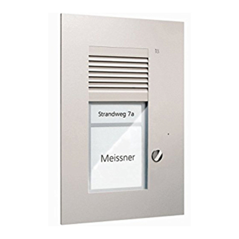
TCS AVU940x0 User manual

TCS TürControlSysteme AG, www.tcsag.de Subject to technical changes.
Product information
VoiP video front-door station series
for flush-mount
AVU940x0

2 11/2012
TCS TürControlSysteme AG, www.tcsag.de Subject to technical changes
Table of content
Scope of delivery...............................................................................................................3
Safety instructions.............................................................................................................3
General safety regulations ...............................................................................................3
Installation –protective measures....................................................................................3
Device overview.................................................................................................................4
Indication and operating elements...................................................................................4
Intended use.......................................................................................................................5
Short description...............................................................................................................5
Mounting and installation .................................................................................................5
Installation site .................................................................................................................5
Installation height .............................................................................................................5
Install flush-mount box .....................................................................................................6
Open the front.door station: the win:clipTM system...........................................................6
Switching diagram: installation with a network .................................................................8
System requirements for the operation via internet..........................................................8
Wiring diagram: examples to connect the relais...............................................................9
Set basic function or standard function on mode switch...................................................9
Fix the front-door station in the flush-mount box ..............................................................9
Commissioning................................................................................................................10
Set volume........................................................................................................................10
Configuration ...................................................................................................................11
System requirements .....................................................................................................11
Prepare network connection...........................................................................................11
Reset to factory settings.................................................................................................11
Examplel: network configuration under Windows 7........................................................12
Network settings.............................................................................................................13
Reset to factory settings.............................................................................................14
Basic settings.................................................................................................................15
SIP parameter................................................................................................................16
Audio settings.................................................................................................................17
Video settings.................................................................................................................18
Relay contacts................................................................................................................19
Time parameter..............................................................................................................21
Call number storage.......................................................................................................22
User settings ..................................................................................................................23
Service...........................................................................................................................24
Video..............................................................................................................................26
Labelling the name field..................................................................................................27
Technical data..................................................................................................................27
Error search .....................................................................................................................28
Cleaning............................................................................................................................29
Conformity........................................................................................................................29
Information on disposal..................................................................................................30
Warranty...........................................................................................................................30
Service..............................................................................................................................30

11/2012 3
TCS TürControlSysteme AG, www.tcsag.de Subject to technical changes.
Scope of delivery
1 x ASU940x0 (incl. flush-mount box)
1 x win:clipTM key
1 x screwdriver with round-handle
name fields, empty and with light symbol
hexagon socket screws (to mount the device in the flush-mount box)
product information
Safety instructions
General safety regulations
!
Attention! Installation, mounting, commissioning and repair of electrical devices have
to be carried out only by qualified electricians. The current standards for the installa-
tion of door communication systems must be observed.
When working in systems with 230 V mains voltage, the safety requirements according to
DIN VDE 0100 must be observed.
When installing TCS:BUS systems, the general safety regulations for telecommunication
systems according to VDE 0800 must be observed. Inter alia:
separated cabling of heavy and low current lines,
minimum distance of 10 cm for common cabling,
use of separators between heavy and low current lines in shared cable ducts,
use of standard telecommunication lines, e.g. J-Y (St) Y with 0.8 mm diameter,
existing lines (modernisation) with deviating cross sections can be used in compliance
with the loop resistance.
Installation –protective measures
!
With suitable requirements to protect against lightning, it has to be ensured that a volt-
age of each 32 V DC is not to be exceeded at the connections +and –.

4 11/2012
TCS TürControlSysteme AG, www.tcsag.de Subject to technical changes
Device overview
Indication and operating elements
name
function
bell button
to trigger a call
4 LED’s, white:
near-field ilumi-
nation
OFF: in stand-by mode
ON: when and after a call is triggered, during a voice
communication, during call from a SIP telephone/PC
blinks: when starting
ASU94040, without name field glass
condensed
water drain
attachement
hole 2: under
diffusion foil
volume control
microphone
loudspeaker
bell button
volume control
loudspeaker
front panel
microphone
attachement
hole 1
opening for
win:clipTM key
diffusion foil
color camera
control noise / echo
suppression
brightness control
near-field illumina-
tion for camera
type label
(under the diffusion foil)
light sensor

11/2012 5
TCS TürControlSysteme AG, www.tcsag.de Subject to technical changes.
Intended use
The front-door stations AVU940x0 are VoiP video front-door stations for door communi-
cation with SIP enabled end devices such as SIP telephones or software telephones
(TCS:Softphone).
The door communication can be realised directly with SIP telephones within an ethernet
network or via internet.
They are suitable for flush-mounting or cavity wall mounting outdoors.
Short description
for 1 to 4 flats
browser based configuration
RJ45 socket to connect the ethernet (10/100 Base-TX) and PoE
day / night switch
win:clip™ principle
bell buttons made of full metal with gold-plated, maintenance-free contacts
volume, microphone sensitivity, echo / noise suppression can be adjusted manually
long lasting and energy saving name field illumination
shatter-proof name plate glass
acknowledgement tone when pressing the bell button
camera field: H 40 mm x W 72 mm
LED illumination for near-field illumination, switchable
video transmission via JPEG stream, H.263, H264
2 x potential-free relay contact (two-way contact: 24 V DC / 2 A), switching time of the
relais ex works: 5 seconds
any bell button can be used to switch the lights, light symbol enclosed
Mounting and installation
Installation site
To achieve a good video image quality, do
not adjust the camera on:
solar radiation,
strong sources of light,
bright or strongly reflective walls.
Installation height
When selecting the installation height of the
video front-door station, the coverage (see
illustration) must be observed. Persons with
an average size can be seen optimal by an
installation height of 160 cm over ground.
3.7 mm lens
56° diagonal capture

6 11/2012
TCS TürControlSysteme AG, www.tcsag.de Subject to technical changes
Install the flush-mount box
Guide the connection lines through the cable conduit in the flush-mount box and fix the
box with suitable screws to the wall.
The front-door station should be flush with the wall.
Open the front-door station: the win:clipTM system
The device is equipped with the win:clipTM system. Opening and closing can be realised
without any screws.
Open the housing
1. Push the enclosed win:clipTM key into the small ope-
ning in the loudspeaker cover.
Press the key into the opening up to the stop and
keep it in this position.
2. Push the name plate glass slightly upwards until it
jumps out.
3. Remove the glass.
4. Remove the win:clipTM key.
Close the housing
1. Push the enclosed win:clipTM key into the small
opening in the loudspeaker cover.
Press the key into the opening up to the stop and
keep it in this position.
2. Push the name plate glass under the loudspeker
cover.
3. Press the name plate glass onto the device and
push it slightly downwards until it snaps-in.
4. Remove the win:clipTM key.
!
Do not seal the device with silicon under any circumstances! Condensed water must
be able to run off and evaporate.

11/2012 7
TCS TürControlSysteme AG, www.tcsag.de Subject to technical changes.
Connect the lines
!
Use the enclosed small screwdriver to connect the lines and further to prevent damag-
ing the device.
The connections are located at the backside of the front-door station.
Connect the lines of the door opener and relays according to the labeling on the type
plate (and illustration below).
Observe, that the door opener must be connected depending on the type of power sup-
ply (see table below).
Connect the front-door stations over the RJ45 connector with the ethernet.
!
It is not necessary to use an external power supply when using a PoE switch. Using an
external power supply could damage the device!
Do not connect!
relay 2 (30 V; 1 A)
relay 1 (30 V; 1 A)
mode switch
power supply 12 - 26 V DC (from NGV1011)
RJ45 connection ethernet/LAN/PoE
no
com
nc
no
com
nc

8 11/2012
TCS TürControlSysteme AG, www.tcsag.de Subject to technical changes
Switching example: installation with a network
System requirements for operating via internet
For the connection via internet telephony you need the widest internet access possible.
For using the TCS:Softphone please also observe the manual TCS:Softphone.
alternative
W-LAN
alternative
W-LAN
(tablet) PC /
laptop
SIP telephone
internal
SIP server
alternative
W-LAN
router / switch
+ –
+ –
SIP-enabled end device
network

11/2012 9
TCS TürControlSysteme AG, www.tcsag.de Subject to technical changes.
Wiring diagram: examples for connecting the relay
Set basic function or standard function at the mode switch
Select the position of the DIP switch 2 according to your system.
When starting or restarting the front-door station, the setting is read out. After starting
the system, the DIP switches 3 and 4 have to be switched to position ON. If not, newly
set values will be overwritten with standard values when restarting the system again.
factory setting
1
not assigned
4
ON: normal
OFF: standard address 192.168.1.250, load net settings
3
ON: normal
OFF: load parameter factory setting
2
ON: system peer to peer direct connection with AVU94x0x
OFF: system SIP server
Fix the front-door station in the flush-mount box
Fix the front-door station with the included hexagon socket screws through the attache-
ment holes on the studs in the flush-mount box.
Ensure that the screws are not over tightened. The housing of the flush-mount box
could deform and front plate and name plate glass can not be installed resp. removed.

10 11/2012
TCS TürControlSysteme AG, www.tcsag.de Subject to technical changes
Commissioning
Install the devices of the system and network completely.
Check the wires against each other for short-circuits.
Switch on the voltage supply. After switching on the voltage supply, the front-door sta-
tion starts automatically.
The configuration of the front-door station is realised with the help of the integrated web
interfaces.
Notes
!
The front-door station restarts automatically after a voltage interruption.
!
Switching off the power supply during a storage process or software update can cause
a loss of data or a device defect.
Set the volume
!
Use the enclosed small screwdriver for setting the potentiometer!
name
function
threshold value
camera illuminati-
on
Set the brightness-dependent switching threshold for the
camera illumination.
volume
loudspeaker
The volumes are set to an average value ex works. A
change is not always necessary.
Observe when setting: increasing the loudspeaker and
the microphone cannot be realised independently from
each other. If the volumes are too large, there will be a
feedback effect (whistling).
volume
microphone
echo / noise supp-
ression
Setting option for the level of the echo / noise suppres-
sion

11/2012 11
TCS TürControlSysteme AG, www.tcsag.de Subject to technical changes.
Configuration
The configuration is realised through the integrated web interface.
Connect a PC to the system.
System requirements
For commissioning and the operation of the IP video front-door station you need a PC with
the following minimum requirements:
State-of-the-art technology,
operating system: WIN2000 or higher, MAC or Linux with graphical user interface,
network connection to the front-door station
internet browser (Internet Explorer, FireFox, Opera, Safari, Chrome)
Preparing the network connection
To ensure that the front-door station can be addressed after the installation, the front-door
station must be allocated to an IP-address in the address area of your network.
To have access to the configuration of the front-door station, the PC must be equipped
with a network connection and located in the same sub net as the front-door station.
If your network and the front-door stations are working in the 192.168.1 address area (C-
net), you can directly access the front-door station (provided that another device is not us-
ing the same IP-address.)
Otherwise, the used PC is to be adjusted temporarily to an IP-address in the address area
of the front-door station to get a connection.
If several front-door stations in delivery condition be installed in a network, the devices
must be commissioned one after the other and assigned to a free IP-address.
To setup the network connection, you might need administrator rights.
When in delivery condition, the following characters are preset in the front-door station:
IP address: 192.168.1.250, sub net mask: 255.255.0.0,
user: admin, password: 1234
Reset to factory settings
In every menu, the settings can be reset to factory settings, simply by pressing the but-
ton factory settings.
Further all settings can be reset with the mode switch:
switch 3: all settings (except the network settings),
switch 4: network settings.

12 11/2012
TCS TürControlSysteme AG, www.tcsag.de Subject to technical changes
Example: network setup under Windows 7
Open the network and dial-up connections in one of the following ways:
Option 1:
Click with the right mouse key start > system control > network and sharing center >
connections: LAN connection > characteristics
Option 2:
Click with the right mouse key on the network icon in the taskbar > open network and
sharing center > connections: LAN connections > characteristics
Click on internet protocol (TCP/IPv4)
(see illustration).
Click on the characteristics button.
Activate “use the following IP addresses:“
Enter an IP address, which differs to those of
the TCS:Server only in the last digit, e.g.
192.168.1.5.
Enter the number of the sub net mask:
255.255.0.0.
Confirm with OK.
0

11/2012 13
TCS TürControlSysteme AG, www.tcsag.de Subject to technical changes.
Network setting
Open an internet browser.
Enter the IP address of the front-door station in the address line: http://192.168.1.250.
The web interface is called.
Host name
Name of the front-door station to distinct the front-door station in the network
(useful if several front-door stations are used).
Setup via DHCP
For activating or deactivating the settings via DHCP.
It is recommended to use a fix IP address to address the front-door station with a
unique IP address.
DHCP Client ID
Name of the client to whom an IP address is assigned to.
The IP address
Address of the front-door station, which is also used to establish a connection to
the front-door station.
Please ask the responsible administrator for the addresses for sub net mask,
standard gateway and DNS server.
Gateway and
DNS server
Only necessary, if the front-door station is also used via the internet. Is the front-
door station only used in an internal network, these fields stay empty. Usually, the
address of the Gateway is not the same as the address of the SIP server.
This is necessary, if the SIP server needs to be addressed with a name, e.g.
Fritz.box. When using a standard router, enter its IP asdress in both fields.
Enter the secundary DNS server only, if a second server can be used.
The noise suppression has to be adjusted only by a TCS service staff!
After finishing the setting press the button store + restart, store the settings.

14 11/2012
TCS TürControlSysteme AG, www.tcsag.de Subject to technical changes
Reset to factory settings
If the IP address was changed manually, the web browser is no longer able to show the
site. If this is the case, enter the new IP address manually in the browser to get back to the
start page. You might also change the address area of your PC again.
If the set IP address or the administrator password is not known, the device can be reset
to factory settings.
Switch off the power supply.
Switch the DIP switches 3 and 4 at the mode switch to OFF.
Switch on the power supply again.
The factory settings are loaded:
IP address: 192.168.1.250
sub net mask: 255.255.0.0
user: admin
password: 1234
After around 2 minutes, the front-door station is accessible again.
Switch the DIP switches 3 and 4 to ON again.

11/2012 15
TCS TürControlSysteme AG, www.tcsag.de Subject to technical changes.
Basic settings
operation mode
2-group-mode: If a number is inaccessible or occupied, the number of the se-
cond group is dialed automatically.
day/night-mode: In day-mode, the number of the first group is dialed, in night-
mode the number of the second group.
button to extend the
communication
Before the maximum communication time is up, the *-button or #-button can be
pressed at the indoor station in order to extend the communication time.
(10 seconds before the communication is terminated automatically, the front-
door station sends a signal tone).
internal hang-up
If this code (2 digits) is entered, the communication ends automatically.
If the codes are identical with those that actuate the relays, the communication
ends after the relay is activated.
code to switch over
To switch between day / night-mode.
Note: After a loss of voltage, please switch in the required mode manually for safety reasons.
switch between
day/night
manually: by entering the fixed codes
automatic: A new menu appears, in which the switch over can be fixed depend-
ing on time. The entry of a time server (menu service) is necessary!
After finishing the settings press the save button.

16 11/2012
TCS TürControlSysteme AG, www.tcsag.de Subject to technical changes
SIP parameter
SIP Proxy server
SIP registration
server
output proxy
SIP account data
Enter IP-address and port of the server, if these data differ from the standard
5060, to send the registration or divert calls.
Name and password are not absolutely necessary, but must be entered exactly
according to the server data.
After the entered data was stored, a registration attempt is triggered (if the name
field is not empty). The result is displayed.
If the registration failed, the reason is displayed in the registration log in in the
menu service.
Name and password are not absolutely necessary, but must be entered exactly
according to the server data.
use ‚180 Ringing‘ /
‚183 Session pro-
gress‘
activate ‚Simmetric
RTP‘
Standard selection of the signalling of incoming calls “180 Ringing“, change pos-
sible to “183 Session progress“, if it is necessary for the SIP-Proxy server.
If it is necessary for the SIP-Proxy server.
After finishing the settings press the save button.

11/2012 17
TCS TürControlSysteme AG, www.tcsag.de Subject to technical changes.
Audio setting
Please execute modifications only in case of audio problems!
In case of audio problems, try to arrange the codecs in another priority to save
bandwidth or to improve the audio quality.
Check the audio settings of the SIP enabled end devices. The SIP enabled end device
must support the codec of the front-door station.
preferred
voice codec
PCMU (G.711 µ-Law) is standard for digital communication in Europe. Very good voice
quality, but also a very high data volume of around 80 to 100 kbit/s.
PCMA (G.711 A-law) is standard for digital communication in North America and Japan.
Very good voice quality, but also a very high data volume of around 80 to 100 kbit/s.
G.726-32
Causes a data volume of around 32 kbit/s with a moderate voice quality.
GSM 6.10 comes from the field of mobile telecommunication. It causes only a low data
volume, by just acceptable quality.
The echo suppresion has to be adjusted only by TCS service staff!
After finishing the stettings press the save button.

18 11/2012
TCS TürControlSysteme AG, www.tcsag.de Subject to technical changes
Video setting
If there is only a low network bandwidth available, set the value for pictures per second
to a lower value or select a smaller image format.
After finishing the settings press the save button.

11/2012 19
TCS TürControlSysteme AG, www.tcsag.de Subject to technical changes.
Relay contacts
relay mode
1 = switching relay closes for the determined period of time when activated
2 = camera relay closes when the call number is dialed and opens if the
communication is over (for external illumination).
3 = staircase light relay closes when dialing the call number and stays closed for
the determined period of time after the communication is over.
4 = bell relay closes after the call button was pressed and opens after the
determined period of time (for external bell).
5 = cascade connection, this mode is only for relay 2, if the relay was programmed
in mode 1.
Function: Relay 1 is activated for the determined period of time. The determined
delay time passes by, then the relay 2 is activated for the determined period of
time.
Note: This process is only started in case relay 1 is activated. Regardless of this, relay 2 can
be activated with the code.

20 11/2012
TCS TürControlSysteme AG, www.tcsag.de Subject to technical changes
activation code
Activation code: With this code the relay is activated by the telephone. The same
code can be used for both relays, thus both relays are activated at the same
time.
Activation codes are entered with the numeric keypad of the SIP enabled end
device.
If *7 is entered in the field, it is only necessary to press 7 on the telephone (* only fills the
digit because the code must have 2 digits.)
relay switch time
Is entered double-digit in seconds [01-99].
To activate a relay
permitted by any
incoming call
Relay switches when a call comes in.
delay between relay
1 and 2 in mode 5
Time in seconds between closing the relay contact 2 after relay contact 1, if relay
2 was programmed in mode 5, double-digit [01-99].
After finishing the settings press the save button.
Table of contents
Other TCS Intercom System manuals

TCS
TCS Carus Adapto User manual

TCS
TCS ASX1300 -0010 Series User manual

TCS
TCS ISW3230-0140 User manual

TCS
TCS PSC2120-0000 User manual

TCS
TCS IVH3222 User manual

TCS
TCS AVD Series User manual

TCS
TCS SKYLINE:TEN BASIC User manual

TCS
TCS ISH3030 Instruction manual

TCS
TCS IVW3012-0110 User manual

TCS
TCS IVH4222-0140 User manual

TCS
TCS IVW2211-0218 User manual

TCS
TCS Tasta Series User manual

TCS
TCS IVW2221-015x User manual

TCS
TCS PDS Series User manual

TCS
TCS ISH3022 User manual

TCS
TCS VPES Series User manual

TCS
TCS PVE14 0-0010 Series User manual

TCS
TCS IMM2500 User manual

TCS
TCS K30001 User manual

TCS
TCS AVU14 0 Series User manual