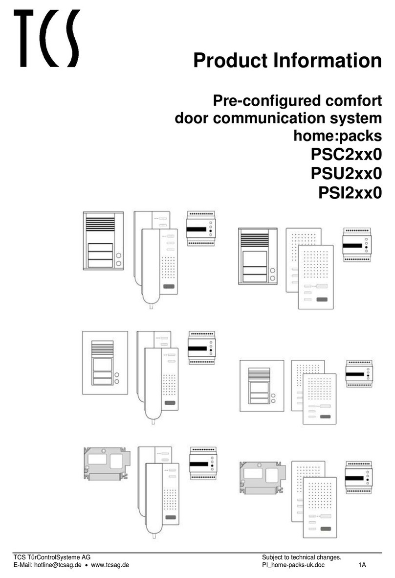
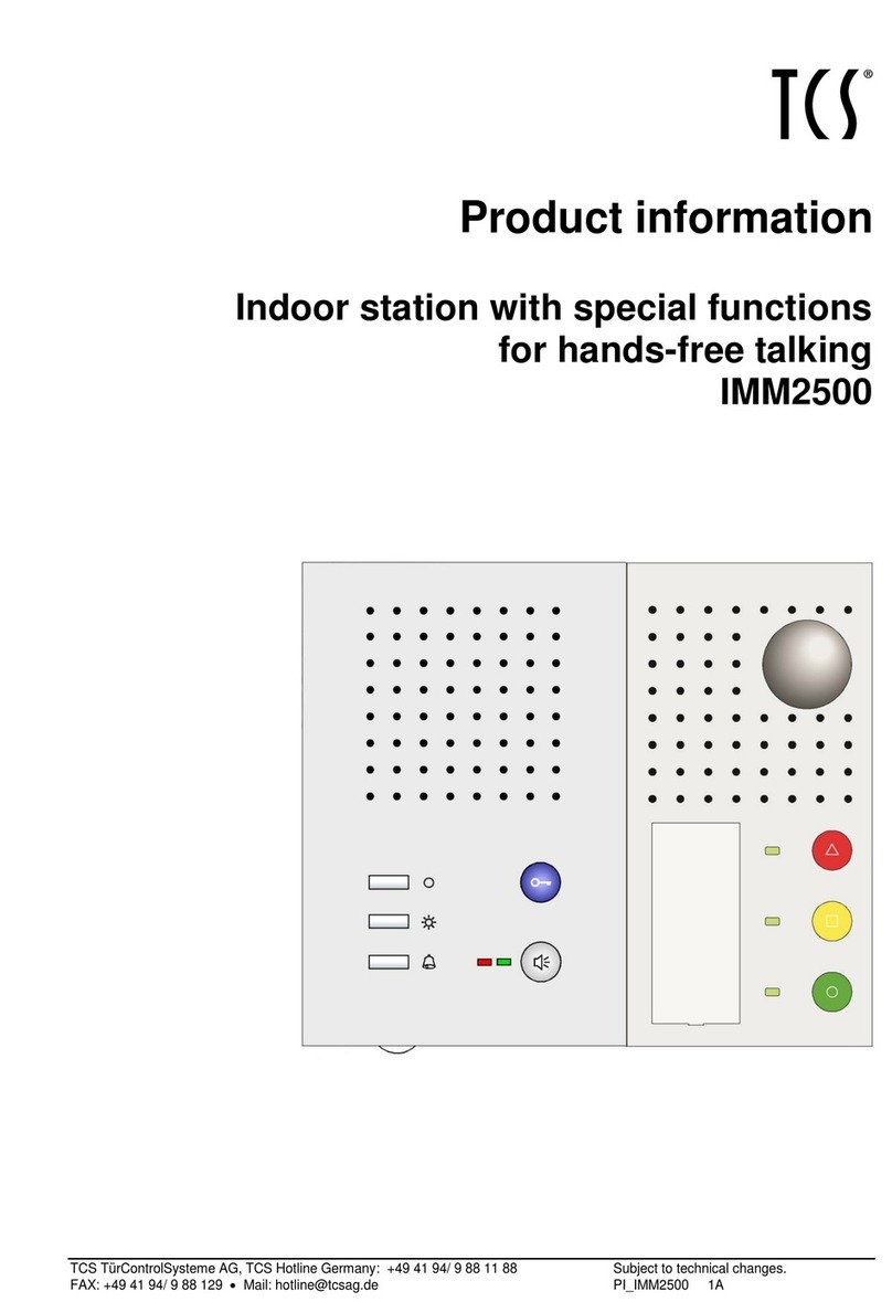
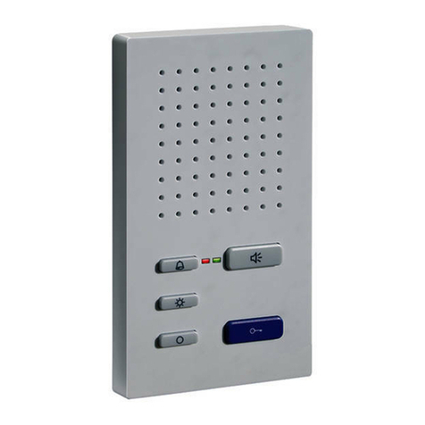
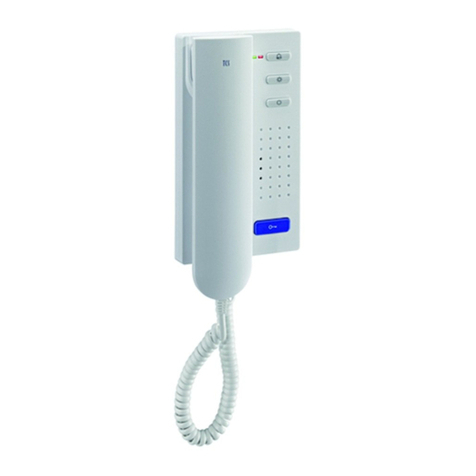
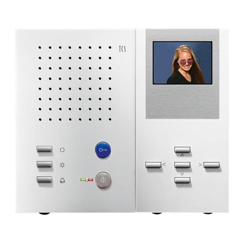
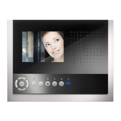
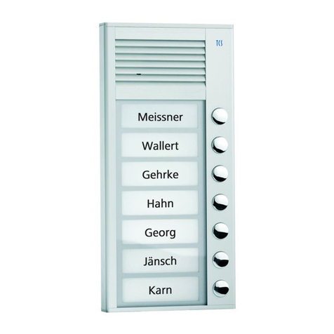
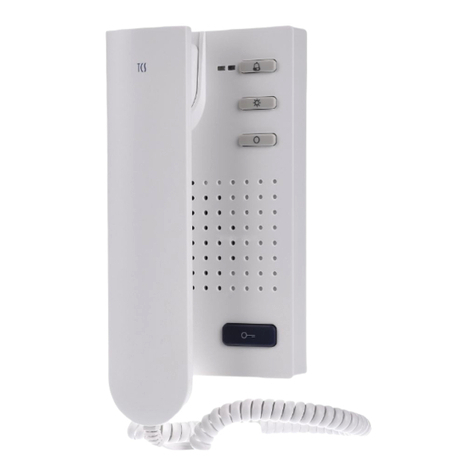
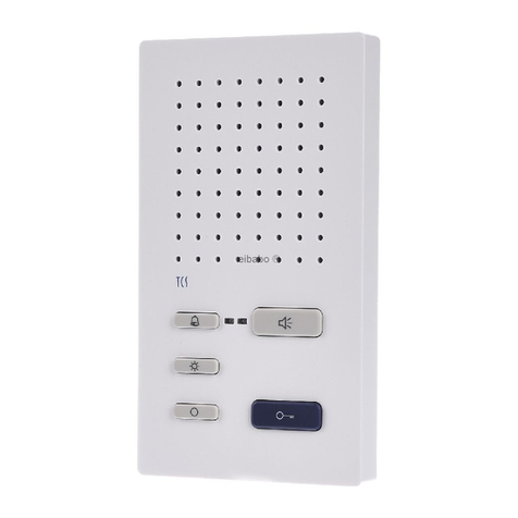
TCS ISW3330 User manual

TCS TürControlSysteme AG, TCS Hotline Germany: hotline@tcsag.de Subject to technical changes.
FAX: +49 (0) 41 94/ 9 88 129 PI_ISW3330-uk 2 A
Product information
Indoor station for hands-free talking
with special functions
ISW3330

2 07/2015
TCS TürControlSysteme AG, TCS Hotline Germany: hotline@tcsag.de Subject to technical changes.
FAX: +49 (0) 41 94/ 9 88 129 PI_ISW3330-uk 2 A
Table of contents
Scope of delivery...............................................................................................................4
Safety regulations..............................................................................................................4
Installation –protective measures....................................................................................4
Intended use.......................................................................................................................4
Max. number ISW3330 (only 3-wire operation possible)..................................................5
Technical data....................................................................................................................5
Device overview.................................................................................................................6
Indication and operating elements...................................................................................6
Short description...............................................................................................................7
Function description.........................................................................................................8
To listen-in rooms.........................................................................................................8
To speak-in rooms........................................................................................................8
Resident calls the central..............................................................................................8
Floor push button..........................................................................................................8
Radio module................................................................................................................8
Grouped announcement from the central to several residents .....................................9
Functionality: assisted living .........................................................................................9
Installation..........................................................................................................................9
Installation site .................................................................................................................9
Install the lower cover.......................................................................................................9
Connect the lines............................................................................................................10
Snap-on the upper cover................................................................................................10
Open the device.............................................................................................................10
Installation of extended functions...................................................................................11
Built-in call relay TRE1-EB/1 ......................................................................................11
Radio receiver board 0022930 ...................................................................................11
Train radio sensors.........................................................................................................11
Connect the lines.............................................................................................................12
Connection lines.............................................................................................................12
Wiring example...............................................................................................................12
Connection diagram 3-wire technique............................................................................13
Commissioning................................................................................................................13
Note (floor push button)..................................................................................................13
Error detection and indication.........................................................................................13
Settings.............................................................................................................................14
Pre-settings ex works.....................................................................................................14
Pre-set times..................................................................................................................14
Set up microphone sensitivity.........................................................................................14
Configuration options .....................................................................................................15
Configure groups............................................................................................................15
Configure floor push button as call push button .............................................................15
Programming with Service Device TCSK-01..................................................................15
General information on the conduit in TCS audio systems.........................................16
Principle loop resistance.............................................................................................17
Measure loop resistance.............................................................................................17
Cleaning............................................................................................................................17
Conformity........................................................................................................................17
Information on disposal ..................................................................................................18
Warranty...........................................................................................................................18

07/2015 3
TCS TürControlSysteme AG, TCS Hotline Germany: hotline@tcsag.de Subject to technical changes.
FAX: +49 (0) 41 94/ 9 88 129 PI_ISW3330-uk 2 A
Spare parts, accessory ...................................................................................................18
Information.......................................................................................................................19
Service..............................................................................................................................20

4 07/2015
TCS TürControlSysteme AG, TCS Hotline Germany: hotline@tcsag.de Subject to technical changes.
FAX: +49 (0) 41 94/ 9 88 129 PI_ISW3330-uk 2 A
Scope of delivery
1 x indoor station ISW3330 (S-11912): upper cover, lower cover
1 x desktop accessory (with connection cable 3 m)
product information
instruction manual
Safety regulations
!
Attention! Mounting, installation, commissioning and repair of electronic devices have
to be carried out only by qualified electricians. Thus, the standards and instructions for
the installation of systems have to be observed!
When installing TCS: BUS®systems, the general safety regulations for telecommunication
systems according to VDE 0800 must be observed. Inter alia:
separated conduit of heavy and low current lines,
minimum distance of 10 cm in case of a common conduit,
use of separators between heavy and low current lines within shared cable ducts,
use of standard communication lines, e.g. J-Y (St) Y with 0.8 mm diameter,
existing lines (modernisation) with deviating cross-sections can be used in compliance
with the loop resistance.
Installation –protective measures
!
With suitable measures to protect against lightning, it has to be ensured that a voltage
of each 32 V DC is not exceeded at the connections a, b, P, E.
Intended use
The ISW3330 are indoor stations for hands-free talking (manually controlled duplex
communication).
They are intended to be operated exclusively in TCS systems with call center!
They are suitable for surface-mount (installation over flush-mount socket) or for desktop
installation with desktop accessory ZIT3030-0010.
3-wire technique necessary!
!
The indoor station ISW3330 must not be used in call systems according to DIN VDE
0834 and EN50134. According to DIN 77800, a separate safeguard for emergency
calls has to be installed.
A system equipped with an indoor station ISW3330 is not an emegency call system
according to the above mentioned standards.
The indoor station ISW3330 must not be used in life-saving or life-sustaining sys-
tems.
Further, the combination of system parts which fulfill the above mentioned standards
is not permitted.

07/2015 5
TCS TürControlSysteme AG, TCS Hotline Germany: hotline@tcsag.de Subject to technical changes.
FAX: +49 (0) 41 94/ 9 88 129 PI_ISW3330-uk 2 A
Max. number ISW3330 (only 3-wire operation possible)
When using the power
supply and control unit
max. number
of ISW3330
NBV3210, 3 strands
30
VBVS05 (PSG02), 1 strand
10
AS front-door station
VS power supply and control unit
IS indoor station
Note: The max. number of AS which can be connected is limited and is descriped in their respective product infor-
mation!
Technical data
supply voltage: +24 V ±8 % (power supply and control unit)
housing: plastics, white
dimensions (in mm): H 180 x W 100 x D 23
weight 180 g
acceptable ambient temperature: -5 ...+ 40 °C
degree of protection: IP30
input current, stand-by I(a) = 0.2 mA, I(P) = 0.8 mA
max. input current: I(Pmax) = 75 mA
3-wire technique necessary!

6 07/2015
TCS TürControlSysteme AG, TCS Hotline Germany: hotline@tcsag.de Subject to technical changes.
FAX: +49 (0) 41 94/ 9 88 129 PI_ISW3330-uk 2 A
Device overview
Indication and operating elements
Call push button
Press: (acknowledgement signal or floor call tone when
pressing the button)
call acceptance, manually controlled duplex communi-
cation after an incoming door call or internal call
calling the central
allow to listen-in into rooms*
end the communication
Lighting bar
Is ON red:
indication of a sent call to the central (expices when
the central reacts or a door or internal call comes in)
indication of a received group call and during a
grouped announcement
* The central can use the control function 8 resp. the floor call to allow the listen-in into rooms again.
Microphone
Lighting bar
Loudspeaker
Volume control
Call push button

07/2015 7
TCS TürControlSysteme AG, TCS Hotline Germany: hotline@tcsag.de Subject to technical changes.
FAX: +49 (0) 41 94/ 9 88 129 PI_ISW3330-uk 2 A
Is ON green:
indication of an incoming door call or internal call (ex-
pices at the start of a BW (assisted living) action or
grouped announcement, timeout 30 sec)
indication of a voice connection (with central or hands-
free talking to a front-door or indoor station)
flashes orange: device or connection error
Volume control for
voice output and ring
tone
Adjustability is deactivated; the volume is set to maxi-
mum.
The volume can only be set at the central (via the user
program call central).
Floor push button
Shortly press: Calling
Sending of a floor call (also sending a control function
8, which can be configured with an own unique serial
number). Acknowledgement signal (or floor ring tone
depending on the configuration) and lighting bar shortly
lights up red.
!
The floor push button cannot be used for call ac-
ceptance and to allow listen-in into rooms.
Short description
manually controlled duplex communication, speech direction is determined by central
large call button
no door release button and no call-OFF button
optical indication by lightning bar
connection option for a floor push button and built-in option for a radio receiver board
up to 5 radio sensors can be trained
!
When planning the system, please observe that a radio transmission can be limited
geographically or can also be disturbed.
listen-in into rooms can be implemented when a resident calls the central
allocation of the device to 3 announcement groups possible
ring tone can be selected out of a pool of 16 ring tones, only with configuration software
configo™
voice volume and ring tone volume are deactivated, always max. volume
optical and acoustic error signaling (can be switched ON / OFF)
programming with configuration software configo™ or user program call central
reproduction of loud tones followed by an announcement
indication of a busy line during a voice connection
audio privacy function and automatic call cut-OFF (after 2 min)
can be functional extended due to installation locations for call relays

8 07/2015
TCS TürControlSysteme AG, TCS Hotline Germany: hotline@tcsag.de Subject to technical changes.
FAX: +49 (0) 41 94/ 9 88 129 PI_ISW3330-uk 2 A
Function description
To listen-in into rooms
It must be guaranteed that there is no way to listen-in into the room, in which the ISW3330
is installed, without the permission from the resident via keystroke at the call button. Lis-
ten-in into the room is only possible, if the resident has called the central (by pressing the
call button, the floor push button or the radio sensor button) or if he presses the call button
or the radio sensor once when the connection is being established (accept voice connec-
tion or in case of a single announcement from the central).
To speak into rooms
After a call from the indoor station, a person at the central can speak-in the room via an
announcement (single announcement).
Resident calls the central
The resident presses the call button at the indoor station, the floor push button, config-
ured with floor call (see Floor push button,page 8) or the button of a trained radio send-
er.
An acknowledgement tone sounds and the lighting bar lights red.
The person in the central calls the resident. A ring tone sounds at the indoor station, the
lighting bar lights green. To communicate with the central, no further action by the resi-
dent is required.
The person at the central can speak into and listen-in into the room. (The central can
change the speech direction. Thus, the resident could talk to the central, if he is within
earshot of the indoor station.)
Floor push button
Pressing the floor push button creates a floor call (= factory setting), which is recog-
nized by the central.
At the ISW3330 sounds the configured floor ring tone as confirmation for the resident.
The central can analyse these signals: and allows these signals and can return the call
and allow to listen-in into rooms.
The floor push button can be used as opening or closing contact. The indoor station can
be configured accordingly with the configuration software configo™.
!
The floor push button cannot be used to accept calls!
Radio module
A radio receiver board (article no. 0022930) can be built-in. Thus, it is possible to trigger
the call also via radio push button, which are available as necklace and bracelet (article
no. 0022931, article no. 00229310022932)
!
When planning the system, please observe that a radio transmission can be limited
geographically or can be disturbed.

07/2015 9
TCS TürControlSysteme AG, TCS Hotline Germany: hotline@tcsag.de Subject to technical changes.
FAX: +49 (0) 41 94/ 9 88 129 PI_ISW3330-uk 2 A
Grouped announcement from the central to several residents
The indoor station supports the protocols for grouped announcements.
Each device can be allocated to three different groups via the configuration software con-
figo™. The group can be called and an announcement can be made to the group.
During a grouped announcement, hands-free talking cannot be realiased.
Pressing the call button, a radio sensor or a floor push button is not accepted. Listen-in
into rooms is not possible.
Functionality: assisted living
The device supports the protocols for assisted living (AL).
During the AL phase, manually controlled duplex communication cannot be implemented.
An established voice connection is ended by the AL protocol.
By pressing the call button during the AL phase a control function 8 is sent. Thus, to
listen-in into rooms, can be implemented.
Installation
Installation site
The indoor station must be installed with a min-
imum distance to walls or other obstacles:
5 cm to the side and 10 cm below.
Install the lower cover
To place the connection cables without any
problems, a flush-mounted socket must be
installed behind the device.
Position the flush-mounted socket below the
cable conduit.
Install the lower cover with three screws.
TIPP: Avoid tearing of the straps:
To fix the cover at the straps, do not use counter-head
screws without flat washers!

10 07/2015
TCS TürControlSysteme AG, TCS Hotline Germany: hotline@tcsag.de Subject to technical changes.
FAX: +49 (0) 41 94/ 9 88 129 PI_ISW3330-uk 2 A
Connect the lines
Minimise the length of the lines above the
lower cover in order to place the lines without
any problems and to prevent clamping the
lines when snapping-on the upper cover.
Connect the lines according to the labelling:
a b E P (from the buttom to the top), floor
push button at a –E.
Wiring example see page 12.
Snap-on the upper cover
Place the upper cover at both adjustment
increments of the lower cover (1).
Snap-on the upper cover below with slight
pressure (2).
Open the device
There is a rectangular release opening at the
underside of the device. Insert a small
screwdriver straight and with slight pressure
into this opening.
The upper cover can be removed at the un-
derside (1).
Lift the upper cover off the two upper adjust-
ment increments (2).
1
2
1
2
Floor push button

07/2015 11
TCS TürControlSysteme AG, TCS Hotline Germany: hotline@tcsag.de Subject to technical changes.
FAX: +49 (0) 41 94/ 9 88 129 PI_ISW3330-uk 2 A
Installation of extended functions
Built-in call relay TRE1-EB/1
Radio receiver board 0022930
The plug for the radio receiver board is located
on the PCB in the upper cover of the special
function module.
Push the contact pins of the radio receiver
board into the designated socket (position see
adjoining illustration).
Ensure that all six pins of the plug of the small
PCB are plugged into the socket.
Position the cable antenna that it is not
clamped when snapping-on the upper cover
and fix it with the adhesive pad (1).
Please observe the product information of each extended function.
Train radio sensors
Training radio sensors can be implemented currently only with the configuration software
configo™ (as of version 1.7.x).
Plug to both
contacts.
1

12 07/2015
TCS TürControlSysteme AG, TCS Hotline Germany: hotline@tcsag.de Subject to technical changes.
FAX: +49 (0) 41 94/ 9 88 129 PI_ISW3330-uk 2 A
Connect the lines
Connection lines
acceptable cross-section (diameter)
0.08 … 0.82 mm2(Ø 0.32 … 1.0 mm)
max. number of wires per terminal contact
each 2 x 0.8 mm, 3 x 0.6 mm
!
Connect further wires with auxiliar terminals!
!
Use only connection lines with identical diameter in one terminal contact.
Wiring example
floor push
button
floor push
button

07/2015 13
TCS TürControlSysteme AG, TCS Hotline Germany: hotline@tcsag.de Subject to technical changes.
FAX: +49 (0) 41 94/ 9 88 129 PI_ISW3330-uk 2 A
Connection diagram 3-wire technique
Commissioning
Install the devices of the system voltage-free and completely.
Check the a-, b- and P-wire against each other for short-circuits.
Switch ON the mains voltage.
Note (floor push button)
If the floor push button does not work, check if it is connected to the a-wire of the power
supply and control unit.
Error detection and indication
The optical and acoustic error indication is deactivated ex works. It can be activated for
service purposes with the configuration software configo™ (see also Information, page
18).

14 07/2015
TCS TürControlSysteme AG, TCS Hotline Germany: hotline@tcsag.de Subject to technical changes.
FAX: +49 (0) 41 94/ 9 88 129 PI_ISW3330-uk 2 A
Settings
Pre-settings ex works
group membership (3 groups)
all 63
serial numbers of up to 5 radio senders
All not assigned
audio AS-border
0 (no call distinction)
ring tones
different for door call, internal call, floor
call
function floor push button
(floor call / control function 8)
floor call
volume control
OFF (always max. volume)
floor push button as opener / closing contact
opener
optical and acoustic error indication (ON/OFF)
OFF
Pre-set times
communication time
max. 2 min
call standby time
2 min, if the device is calling
30 s, if the device is called
timeout group call
2 min
timeout announcement (group and single)
internal standby time, if the device is calling or
is called
around
30 sec
Set up microphone sensitivity
Can be continuously adjusted at the control
microphone sensitivity.
This setting influences only the sensitivity of the
microphone when listen-in into rooms.
Note: During hands-free talking, the microphone sensitivity
does not change.

07/2015 15
TCS TürControlSysteme AG, TCS Hotline Germany: hotline@tcsag.de Subject to technical changes.
FAX: +49 (0) 41 94/ 9 88 129 PI_ISW3330-uk 2 A
Configuration options
Function
manually
configoTM
as of vers. 1.7.x
ring tone volume
x
–
conversation volume
x
–
microphone sensitivity
x
–
select ring tones for door call 1, internal call and floor calls
–
x
ring tone for door call 2
–
x
change audio AS-border
–
x
ring tone for BW protocol
–
x
tone for group call protocol
–
x
determine the function of the floor push button (floor call /
control function 8, opener / closing contact)
–
x
always max. volume, volume control is deactivated (ON /
OFF)
–
x
optical and acoustic error indication ON / OFF
–
x
allocate to 3 groups
–
x
allocate serial numbers of up to 5 radio sensors
–
x
Configure groups
Each indoor station can be allocated to three different groups. Thus, an announcement
can be implemented e.g. at the floor and alternatively in a staircase.
Factory setting: all three with value 0, can be changed to 1 … 63.
The functions can be configured with the configuration software configo™.
!
During an announcement or during the loud tone output, the device is blocked for the
user. Also door calls, internal calls and floor calls are blocked.
Configure floor push button as call push button
Push button with a minimum switch time of 1 sec can be connected.
The configuration can be implemented only with the configuration software configo™
!
The floor push button cannot be used for call acceptance and to allow the listen-in into
rooms.
Programming with Service Device TCSK-01
The indoor station is acting as a manually controlled duplex communication device. On-
ly searching for the device can be implemented
search for manually controlled duplex communica-
tion devices
Configuration is implemented with the configuration software configo™.

16 07/2015
TCS TürControlSysteme AG, TCS Hotline Germany: hotline@tcsag.de Subject to technical changes.
FAX: +49 (0) 41 94/ 9 88 129 PI_ISW3330-uk 2 A
General information on the conduit in TCS audio systems
The conduit is determined by structural conditions and is limited only by its length.
Observe when selecting the cable length: the
loop resistance must not exceed 8 Ω(table).
To keep the max. permitted loop resistance, the
cross-section of the wire can be doubled, that
means, for one wire two lines are used (illustra-
tion). The lines must be twisted.
When using shielded lines: connect the shields
with each other and connect one side to ground
(b-wire) at the power supply
optional strand or star shaped wiring
Table: loop resistances
cable length in m
cable diameter
0.6 mm
0.8 mm
loop resistance in Ω
10
1.28
0.71
20
2.55
1.43
30
3.83
2.14
40
5.10
2.86
50
6.38
3.57
60
7.65
4.29
70
8.93
5.00
80
5.71
90
6.43
100
7.14
150
10.71
R/L W/Y W/G W/Br W|B/W

07/2015 17
TCS TürControlSysteme AG, TCS Hotline Germany: hotline@tcsag.de Subject to technical changes.
FAX: +49 (0) 41 94/ 9 88 129 PI_ISW3330-uk 2 A
Principle loop resistance
Measure loop resistance
None of the devices (AS, IS or FE) should be fur-
ther than 20 Ohm away from the power supply and
control unit (VS).
Switch OFF the 230 V / 50 Hz of the VS.
Install a-b short-circuit at the VS.
Other devices are not disturbing the measure-
ment, they can stay connected.
Measure the resistance at a/b at the last IS or AS.
8 Ohm:
max. 62 m distance AS/IS-VS by 0.6 mm diameter
max. 112 m distance AS/IS-VS by 0.8 mm diameter
AS front-door station
VS power supply and control unit
IS indoor station
FE extended function
Cleaning
!
Avoid water from entering the device!
Do not use any abrasive detergents!
Clean the device with a dry or slightly wet cloth.
Remove stronger stains with a standard plastic cleaner.
Conformity
The declarations of conformity are available under www.tcsag.de, downloads, trade
information.
a, b short-circuit
here

18 07/2015
TCS TürControlSysteme AG, TCS Hotline Germany: hotline@tcsag.de Subject to technical changes.
FAX: +49 (0) 41 94/ 9 88 129 PI_ISW3330-uk 2 A
Information on disposal
The adjoining symbol shows, that the device has to be disposed separately from
domestic waste. The material used are recycable. Please do help protecting our
environment and dispose the device via a collection point for electronic scrap.
Dispose the parts of the packaging in collecting tanks for cardboard and paper
resp. plastics.
Warranty
We offer a simplified processing in case of warranty for electricians.
Please note our conditions of sale and delivery, download from www.tcsag.de, down-
loads, trade information.
Please contact the TCS HOTLINE.
Spare parts, accessory
Short text
Article number
10 x lower cover ISx3xxx-x140
E32431
10 pieces cover panels white 120 x 250 x 2 mm
E24340
radio receiver board
0022930
radio sensor,wristband
0022931
radio sensor, necklace
0022932

07/2015 19
TCS TürControlSysteme AG, TCS Hotline Germany: hotline@tcsag.de Subject to technical changes.
FAX: +49 (0) 41 94/ 9 88 129 PI_ISW3330-uk 2 A
Information
The indoor station can be configured to the customer’s requirements by configuring the user software call
central ex works.
Operation
The resident calls the central by pressing the call button or radio sensor. An acknowledgement tone
sounds and the lighting bar is lighting up red. By pressing the call button or radio sensor, the resident ac-
cepts, that from this moment on until the end of the communication, the central is allowed to listen-in into the
room.
The person in the central can select single residents and call them. This internal call from the central triggers
a call at the indoor station ISW3330. A ring tone sounds, the lighting bar is lighting up green. After accepting
the call by pressing the call button at the indoor station or radio sensor, a manually controlled duplex com-
munication is established. The person at the central can change the speech direction and is able to listen-in
into the room.
If the call is not accepted, a single announcement can be implemented by the person in the central (”Help is
on the way.“).
The resident calls the central by pressing the floor push button. An acknowledgement tone sounds. The
person in the central can select single residents and call them. This internal call from the central triggers a
call at the indoor station ISW3330. A ring tone sounds, the lighting bar is lighting up green. If the resident is
able to accept the call (by pressing the call button at the indoor station or the radio sensor), a manually con-
trolled duplex communication is established. The person at the central can change the speech direction and
is able to listen-in into the room.
If the call is not accepted, a single announcement can be implemented by the person in the central (”Help is
on the way.“).
The resident is called by the central and a single announcement is started immediately. (Listen-in into
rooms is not possible at that point). If the resident presses the call button, the radio sensor or the floor push
button during this phase, the standard control function is sent. This is the signal for the central, which allows
the listen-in into rooms.
Note: In contrast to the TTN30 and IMMx500 devices, it is not possible to establish a bidirectional voice connection in
this phase. The control of the speech direction always stays at the central.
Error detection and indication
When in delivery state, the optical and acoustic error indication can be activate.
It can be deactivated after a successful commissioning with the configuration software configo™.
Errors are signaled optically and acoustically: single error tone and permanent flashing of the lighting bar.
When pressing any button, the error tone sounds again. The optical error indication stays active until the
error is corrected.
error causes
indicati-
on error
mode
error tone
solution
a- and P-wire are inter-
changed or short-circuited
Lighting
bar flas-
hes
orange
Exchange a- and P-wire or eliminate short-circuit,
device is in standby mode again
a-wire: not connected or
not supplied
Connect the a-wire or check the power supply,
device is in standby mode again
call button (or floor push
button, opener) is stuck
(pres longer than 25 sec)
Loosen button at the device (or floor push button, if it
configured as opener).
device is in standby mode again

20 07/2015
TCS TürControlSysteme AG, TCS Hotline Germany: hotline@tcsag.de Subject to technical changes.
FAX: +49 (0) 41 94/ 9 88 129 PI_ISW3330-uk 2 A
Service
Please send your questions and inquiries to
Headquarters
TCS TürControlSysteme AG, Geschwister-Scholl-Str. 7, 39307 Genthin
Phone: +49 (0) 3933 / 879910, FAX: +49 (0) 3933 / 879911, www.tcsag.de
Other manuals for ISW3330
1
This manual suits for next models
1
Table of contents
Other TCS Intercom System manuals

TCS
TCS IVW2221-015x User manual

TCS
TCS IVX9001-0140 User manual

TCS
TCS IVW2211-0218 User manual

TCS
TCS SKYLINE:TEN BASIC User manual

TCS
TCS CAI2002-0140 User manual

TCS
TCS AVU940x0 User manual

TCS
TCS VPES Series User manual

TCS
TCS IVW9011-0261 User manual

TCS
TCS ECOOS:FIVE User manual

TCS
TCS Tasta Series Instruction manual

TCS
TCS PDS Series User manual

TCS
TCS ISH3230 User manual

TCS
TCS ISW3230-0140 User manual

TCS
TCS IVH3222 User manual

TCS
TCS ISW3230-0140 User manual

TCS
TCS ASX1300 -0010 Series User manual

TCS
TCS IVH4222-0140 User manual

TCS
TCS Carus Origo User manual

TCS
TCS ISW5010-0145 Instruction manual

TCS
TCS AVC11010-0010 User manual