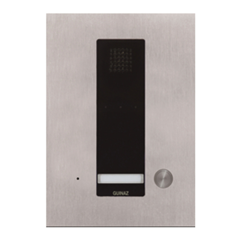
Guinaz PDV501SIP User manual

PLACA CALLE SISTEMA IP
REF. PDV501SIP
STREET PANEL IP SYSTEM
REF. PDV501SIP
GUÍA DE INSTALACIÓN /INSTALLATION GUIDE

2 G503212 REV.0
ÍNDICE:
INDEX:
1. INTRODUCCIÓN AL SISTEMA IP GUINAZ. Características generales……………………………………………. 3
INTRODUCTION TO THE GUINAZ IP SYSTEM. General Features.
2. INSTALACIÓN PLACA DE CALLE……………………………………………………………………………………. 4
ENTRY PANEL INSTALLATION
2.1 Colocación de la placa de calle……………………………………………………………………………... 4
Placing Entry Panel
2.2 Colocación del tarjetero………………………………………………………………………………………. 5
Placing of the name card.
2.3 Recomendaciones de instalación de la placa de calle…………………………………………………….. 5
Installation Recommendations for Entry Panels.
3. MODO DE FUNCIONAMIENTO……………………………………………………………………………………… 7
MODE OF OPERATION
4. BORNAS DE CONEXIÓN…………………………………………………………………………………………….. 7
TERMINAL CONNECTION
5. CONEXIÓN DEL MÓDULO Y ACCESO AL SERVIDOR WEB……………………………………………………… 8
MODULE CONNECTION AND WEB SERVER ACCESS
5.1 DUAL SERVER. Asignación dirección IP a placa calle GUINAZ IP……………………………………….. 10
DUAL SERVER. Assigning IP address to GUINAZ IP Entry Panel.
6. CONFIGURACIÓN A TRAVÉS DEL SERVIDOR WEB………………………………………………………………. 12
CONFIGURATION THROUGH THE WEB SERVER
6.1 Descripción de los parámetros de configuración………………………………………………………….. 12
Description of configuration parameters.
6.2 Acceso al servidor web………………………………………………………………………………………. 17
Web Server Access
6.3 Configuración modo P2P-SIP……………………………………………………………………………….. 19
P2P-SIP configuration mode
6.4 Configuración modo IPBX…………………………………………………………………………………… 24
Configuring IPBX mode
6.5 Reset hardware………………………………………………………………………………………………. 27
Hardware Reset
7. DIAGNÓSTICO Y PREGUNTAS FRECUENTES……………………………………………………………………. 28
DIAGNOSIS AND FAQ

G503212 REV.0 3
1. INTRODUCCIÓN AL SISTEMA IP GUINAZ. Características generales.
INTRODUCTION TO THE GUINAZ IP SYSTEM. General Features.
Los equipos de placa de calle GUINAZ IP permiten al usuario
establecer una comunicación de audio y video a través de
una red IP. Incluyen una capa de control para la gestión del
acceso a través de una puerta, y la conexión de hardware
externo para el control de la iluminación, para la
monitorización del estado de dicha puerta.
Sincronización de audio y video.
El uso del protocolo SIP garantiza la sincronización entre los
flujos de audio y vídeo, que son enviados bajo la misma
sesión (SDP).
Comunicación bidireccional.
Audio bidireccional dotado de cancelación de eco.
PoE.
Alimentación a través del conector Ethernet. Es posible
alimentar el dispositivo utilizando el cableado de red. Para
ello necesitará un router o switch PoE o un inyector.
Configuración web.
Servidor web integrado para la configuración sencilla e
intuitiva del equipo. El mismo servidor incluye cuadros
informativos que indican al usuario el uso de cada parámetro.
Control de abrepuertas.
Aplicación para el control de una puerta, configurable desde
el servidor web. Permite activar un relé de apertura de puerta
de manera remota o desde el interior de un recinto mediante
la pulsación de un botón instalado para tal efecto.
Control de iluminación.
Es posible activar un circuito de iluminación externa tras la
pulsación del botón de llamada.
Generación de alarmas.
Existe una entrada dedicada para la conexión de un sensor
que detecta cuando la puerta se ha quedado abierta. Se
puede configurar el dispositivo para que si la puerta
permanece abierta durante un tiempo determinado, se active
una alarma que alerte de dicho estado.
Diagnóstico de pruebas.
El servidor web incluye una pestaña de diagnosis en la que
se pueden identificar problemas relacionados con el altavoz,
el micrófono o la imagen.
Características del sensor de imagen.
Array: 640x480.
Lente: 1/9”.
Sensibilidad: 1800mV/lux-sec
Apertura: 66º
Transmisión máxima: VGA@30fps.
The GUINAZ Entrance panel allows the user to communicate
audio and video over an IP network. It includes a control layer
for managing access through a door, and connecting external
hardware to the lighting control for monitoring the state of the
door.
Audio and video synchronization.
The use of the SIP protocol ensures synchronization between
audio and video streams, which are sent on the same session
(SDP).
Bidirectional communication.
Bidirectional audio echo cancellation provided.
PoE.
Power over Ethernet connector. You can power the device
using the network cabling. You will need a router or switch PoE
or a injector.
Web Configuration.
Integrated web server for easy unit configuration and intuitive
one. The same server includes informative tables that indicates
the user how using each parameter.
Opener Control.
Application for a door control, configurable from the web
server. It allows to activate a door opener relay remotely or
from within an enclosure by pressing a button installed for this
purpose.
Lighting control.
You can activate an external lighting circuit after pressing the
call button.
Alarm generation.
There is a dedicated input for connecting a sensor that detects
when the door is left open. You can configure the device so
that if the door remains open for a specified time, an alarm to
alerts the state.
Diagnostic tests.
The web server includes a diagnostics tab in which problems
can be identified with the speaker, microphone or image.
Features Image Sensor.
Array: 640x480.
Lens: 1/9. "
Sensitivity: 1800mV/lux-sec
Open: 66 °
Maximum Transmission: VGA @ 30fps.

4 G503212 REV.0
2. INSTALACIÓN PLACA DE CALLE.
STREET PANEL INSTALLATION.
2.1 Colocación de la placa calle.
Placing of the street panel.
1.Coloque la caja empotrable.
Place the flush-mounted box.
2.Afloje los dos tornillos inferiores hasta liberar el marco
interior.
Loosen the bottom two screws to release the inner frame.
3.Separe el marco interior de la placa calle.
Separate the inner frame of the street panel.
4.Sujete el marco interior a la caja empotrable mediante dos
tornillos.
Hold the inner frame to the flush-mounted box with two
screws.
5.Extraiga las piezas de apoyo para mantener la placa de
calle abierta.
Move de pieces of support to keep the street panel open.
6. Apoye la placa de calle sobre el marco interior. Conecte
los cables de la instalación.
Support the street panel in the inner frame. Connect de
cables of the installation.

G503212 REV.0 5
7. Descuelgue la placa calle del marco interior. Coloque
las piezas de apoyo en la posición inicial.
Release the street panel of the inner frame. Place the
pieces of support in the initial position.
8. . Coloque la placa de calle en el marco interior. Sujete la
placa de calle apretando los dos tornillos inferiores.
Place the street panel in the inner frame. Hold the street
panel by tightening the inferior two screws.
2.2 Colocación del tarjetero.
Placing of name card.
1.Extraiga la tapa de plástico transparente.
Remove the transparent plastic cover.
2.Sustituya la tarjeta. Coloque de nuevo la tapa de plástico
transparente.
Replace the card. Replace the transparent plastic cover.
2.3 Recomendaciones de instalación de la placa calle.
Recommendations for installation of the street panel.
La placa de calle está suficientemente
protegida de las condiciones atmosféricas.
Sin embargo, es conveniente instalarla en
un lugar en que no afecten directamente
agentes como la lluvia, humedad, etc.
Cuando la placa calle esté expuesta a la
intemperie se recomienda instalarla sobre
un marco visera. En el caso de superficies
no lisas, donde la placa calle o el marco
visera no queden perfectamente sellados
mediante las juntas que incorporan, se
recomienda aplicar algún sellante en toda
la parte superior de la placa calle o marco
visera para evitar entradas de agua que
puedan dañar el equipo.
The street panel is sufficiently protected
against atmospheric conditions. However, it
is recommendable to install it in a place
where agents such as rain, humidity, etc.
cannot affect it.
When the panel is exposed to the elements
it is recommendable to install it with a visor
frame. In the case of surfaces that are not
smooth, where the street panel or visor
frame are not perfectly sealed with the joints
that are incorporated, then some sort of
sealer should be applied throughout the
entire upper part of the street panel or visor
frame to thus avoid water from penetrating
and damaging the equipment.

6 G503212 REV.0
En la instalación de videoportero, se ha de
escoger un lugar donde no incida
directamente una fuente de luz (sol, farolas,
etc.) sobre la telecámara, para evitar el
efecto de contraluz en la imagen.
En el caso de que la imagen no sea nítida
debido a luz insuficiente para la telecámara,
se ha de colocar una iluminación auxiliar
como se indica en la figura. Esta iluminación
auxiliar puede instalarse de tal forma que
sólo se ilumine la escena cuando haya un
monitor funcionando.
When choosing the location to install a
video door entry system it is important to
find a location where the source of light
(sun, street lamps, etc.) does not directly
affect the camera, to thus avoid the effect of
the back light on the image.
If the image is not clear and sharp due to a
lack of light for the camera, then auxiliary
lighting should be placed as is duly
indicated in the figure. This auxiliary lighting
can be installed in such a way that it only
lights up the scene when a monitor is
working.
La manipulación interna del equipo sólo puede realizarse por personal especializado, y siempre con el equipo desconectado de la
alimentación.
Internal manipulation of equipment can only be executed by specialized personnel and always with the equipment disconnected
from the power source.

G503212 REV.0 7
3. MODO DE FUNCIONAMIENTO.
OPERATING MODE.
1. Al presionar el pulsador, se establece la llamada con la
dirección IP previamente configurada. El módulo emite
un tono de llamada que indica al usuario que la llamada
se está realizando.
2. Si el punto de destino no está disponible y la llamada de
reserva está activada, se realizaría una segunda llamada
a un destino secundario (de reserva) previamente
configurado.
3. Cuando una llamada está activa, se puede controlar
desde el punto de destino el relé de puerta del módulo
con unos códigos previamente configurados. Estos
códigos permiten abrir y cerrar el relé temporalmente o
de forma permanente.
4. Al presionar cualquiera de los pulsadores para
establecer una comunicación, el relé de iluminación se
activará. Esto permitiría habilitar un mecanismo externo
de iluminación durante el periodo en el que la llamada
esté activa.
5. El módulo dispone de una entrada para instalar un
pulsador o botón de salida. Tras presionar el botón de
salida, se activará temporalmente el relé de apertura de
puerta.
6. Si se desea realizar un control sobre el estado de la
puerta, es posible conectar una entrada de la placa de
calle GUINAZ IP a un sensor de puerta. Si esta
funcionalidad está activada, cuando la puerta se quede
abierta durante un intervalo configurable, se emitirá un
mensaje de alarma bien por el altavoz del
intercomunicador o mediante una llamada a un destino
de alerta preconfigurado en el equipo.
1. By pressing the button, the call is established with the
previously configured IP address. The module emits a
tone that indicate the user that the call is being made.
2. If the destination is not available and the reservation call
is on, you would make a second call to a secondary
destination (reservation call) preconfigured.
3. When a call is active, you can control from the point of
destination the relay module door with a pre-configured
codes. These codes allow you to open and close the
relay temporarily or permanently.
4. Pressing any of the buttons for communication, lighting
relay will be activated. This would enable an external
mechanism of illumination during the period in which the
call is active.
5. The module has an entry to install a push button or exit
button. After pressing the exit button, temporarily it
enables door opening relay.
6. If you want to perform a check on the status of the door,
you can connect an entry of the Guinaz IP street panel to
a door sensor. If this feature is enabled, when the door is
left open for a configurable interval, it will issue a warning
message either by the intercom speaker or through a call
to a preconfigured alert destination on your computer.
4. BORNAS DE CONEXIÓN.
TERMINAL CONNECTION.
RED
NO C NC
+5VDC/GND
NO C NC+V -V
PA
IN OUT OUT IN IN
PDV501SIP

8 G503212 REV.0
IN. +5VDC/GND. ALIMENTACIÓN (+5VDC/1A).
Conexionado de fuente de alimentación externa F1350.
PoE / Red: Alimentación a través de PoE. Ethernet
10/100.
OUT. RELÉ DE PUERTA. Contacto libre de potencial. El
relé se activa a través del teclado del dispositivo remoto
de control.
OUT. RELÉ DE ILUMINACIÓN. Contacto libre de
potencial. El relé se activa al presionar el pulsador de
llamada. Es posible su activación y desactivación desde
el teclado del dispositivo remoto de control.
IN. PA. SENSOR DE PUERTA ABIERTA. Contacto libre
de potencial. Conexión de sensor externo para detectar
si la puerta queda abierta. Se deberá seleccionar el tipo
de sensot (NO ó NC) desde el webserver.
IN. PULSADOR DE SALIDA. Contacto libre de potencial.
Para conexión de pulsador externo que permita la
apertura desde el interior.
Características de los relés de salida (para carga
resistiva):
Corriente máxima: 2A.
Potencia máxima: 60W / 62.5A.
Tensión máxima: 220VDC / 250VAC.
NOTA: Para conexión de cargas NO resistivas, se
recomienda aislar el equipo de la carga mediante un relé
R2620.
IN. +5 VDC / GND. POWER (+5 VDC/1A). Connection of
external power supply F1350.
PoE / Red: Power over PoE. Ethernet 10/100.
OUT. RELAY DOOR. Potential free contact. The relay is
activated through the keyboard remote control device.
OUT. RELAY LIGHTING. Potential free contact. The relay is
activated by pressing the call button. It is possible to
activate and deactivate from keypad of the remote control
device.
IN. PA. OPEN DOOR SENSOR. Potential free contact.
Connecting external sensor to detect if the door is open.
They must select the type of sensor (NO or NC) from the
webserver.
IN. EXIT BUTTON. Potential free contact. For connection
of external button that allows opening from the inside.
Characteristics of the output relays (for resistive load):
Maximum current: 2A.
Maximum power: 60W / 62.5A.
Maximum voltage: 220VDC / 250VAC.
NOTE: For NO resistive loads connection, it is
recommended to isolate the equipment from the load
through a relay R2620.
5. CONEXIÓN DEL MÓDULO Y ACCESO AL WEBSERVER.
MODULE CONNECTION AND ACCESS TO WEBSERVER.
La configuración de los módulos se realiza a través de un
servidor web embebido en el dispositivo. A continuación se
describe el proceso de conexión y acceso al webserver de
configuración de la placa de calle GUINAZ IP.
PASO 1. Conecte la placa de calle GUINAZ IP a su red.
Introduzca la dirección MAC del módulo en su servidor DHCP
asignándole la dirección IP deseada.
PASO 2. Alimente el módulo. Puede hacerlo a través de un
switch PoE o un inyector Poe, si no dispone de ninguno de
estos equipos o no desea utilizar alimentación PoE, deberá
utilizar el alimentador externo F1350.
The module configuration is done through a web server
embedded in the device. The following steps describe the
connection process and access to the webserver
configuration of GUINAZ IP Entry Panel.
STEP 1. Connect the GUINAZ IP Panel to your network. Enter
the MAC address of the module into the DHCP server
assigning the desired IP address.
STEP 2. Feed the module. You can do this through a PoE
switch or Poe injector , if you don´t have any of these
equipments or don´t wish to use PoE power, you must use the
external power supply F1350.

G503212 REV.0 9
PASO 3. Teclee en el navegador de un PC conectado a la
red, la dirección IP asignada a la placa de calle GUINAZ IP
por su servidor DHCP. Introduzca los datos de usuario y
contraseña. Utilice los navegadores Google Chrome o Mozilla
Firefox para los que está optimizado el webserver.
Todas las placas de calle GUINAZ IP reciben la configuración
por DHCP, y tienen un usuario y contraseña de acceso al
webserver, por defecto:
Usuario: admin
Contraseña: root
Por motivos de seguridad, GUINAZ recomienda cambiar la
contraseña de acceso.
PASO 4. Cambie la contraseña de acceso al webserver por
una de su confianza. Este paso es recomendable y lo puede
hacer en cualquier momento de la configuración.
PASO 5. El webserver tiene en la parte inferior un espacio
dedicado a mostrar la información de cada campo. En la guía
de usuario encontrará información detallada sobre los
parámetros de configuración. En la pestaña “Contactos”
deberá de introducir la dirección de destino de llamada. Si no
quiere utilizar la llamada de reserva deje este campo vacío.
PASO 6. Tras los cambios en la configuración de una
pestaña, pulse “Aplicar cambios”. En este momento los
cambios estarán salvados pero se perderán tras un reinicio
del módulo. Si quiere salvar la configuración de manera
permanente, pulse “Salvar” en el mensaje que aparecerá en
la parte superior avisándole de este hecho. Tras pulsar, el
módulo mostrará mensaje de confirmación y se reiniciará con
la configuración que haya seleccionado.
STEP 3. Type in the browser of a PC connected to the
network, the IP address assigned to the GUINAZ IP Entry Panel
by your DHCP server. Enter the username and password data.
Use the browsers Google Chrome or Mozilla Firefox that is
optimized for the webserver.
All GUINAZ IP Entry Panels receive the settings through
DHCP, and have a username and password to access the
webserver, by default:
Username: admin
Password: root
For security reasons, GUINAZ recommended to change the
password.
STEP 4. Change the password to access the webserver by a
trust one. This step is recommended and can be done at any
time of the configuration.
STEP 5. The webserver has at bottom a space dedicated to
displaying information in each field. In the user guide you will
find detailed information on the configuration parameters. In
the tab "Contacts" you must introduce the call destination
address. If you do not want to use the reservation call, leave
this field empty.
STEP 6. After changes done in the configuration of a tab, press
"Apply Changes". At this time, changes will be saved but they
will be lost after a reboot of the module. If you want to save the
setting permanently, press "Save" in the message that appears
on top, alerting you to this fact. After pressing “ Save”, the
module will display confirmation message and reboot with the
settings you have selected.
Conexión con un PC usando alimentador externo (ref.F1350).
Connecting to a PC using external power (ref. F1350).
Conexión a un PC a través de elementos POE.
Connecting to a PC via POE elements.
Cable
Ethernet
Ethernet
cable
Alimentador F1350
F1350 power supply
Switch o inyector POE
Switch or POE injector

10 G503212 REV.0
5.1 DUAL SERVER. Asignación de dirección IP a placa de calle GUINAZ IP.
DUAL SERVER. Assigning IP address to GUINAZ IP Entry Panel.
Por defecto, la placa GUINAZ IP tiene asignada su
correspondiente dirección IP por DHCP. Si no tiene la
posibilidad de conocer la IP asignada al equipo, una forma
sencilla de realizar la configuración es conectar directamente
la placa de calle GUINAZ IP al ordenador e instalar un
programa que funcione como servidor DHCP. En este
apartado se explica cómo hacerlo con el programa “DUAL
SERVER”.
El enlace de descarga de este programa:
http://sourceforge.net/projects/dhcp-dns-server/
Como primer paso, se ha de establecer la conexión física
entre el PC y la placa de calle GUINAZ IP vía ethernet a través
del conector RJ45.
By default, GUINAZ IP entry panel has assigned its
corresponding IP address by DHCP. If you do not have the
ability to know the IP assigned to the computer, a simple way
to make the configuration is connecting directly GUINAZ IP
Entry Panel to the computer and install a program that works
as a DHCP server. This section explains how to do it with the
program "DUAL SERVER".
The download link for this program is:
http://sourceforge.net/projects/dhcp-dns-server/
As first step, it has to be established the physical connection
between the PC and the GUINAZ IP Entry Panel through the
RJ45 connector.
Se configura la IP fija de nuestro PC:
Static IP is configured on your PC:
Se edita el archivo “DualServer.ini”.
You edit the file "DualServer.ini".
Modificar los siguientes parámetros:
Modify the following parameters:
[SERVICES]
Nueva dirección IP asignada al PC.
New IP address assigned to the PC.
Máscara de subred asignada.
Subnet Mask assigned.
Se asignará la
dirección IP
manualmente. .
It will assign the IP
address manually.
Puerta de enlace predeterminada =
dirección IP asignada.
Default Gateway = IP address assigned.
Anular las funciones DNS y
DHCP añadiendo “;” delante
de cada uno de ellos.
Cancel DNS and DHCP
functions by adding ";" in front
of each of them.

G503212 REV.0 11
[LISTEN_ON]
Al final del programa:
At the end of the program:
Correr el programa dual server. Iniciar desde el archivo Run standalone.
Running dual server program. Start from the Run standalone file.
Nueva dirección IP asignada al PC.
New IP address assigned to the PC
MAC de la placa de calle GUINAZ.
Ver en pegatina de la placa calle.
MAC GUINAZ IP Entry Panel.
See sticker at the entry panel.
Nueva dirección IP asignada a la
placa de calle GUINAZ.
New IP address assigned to
GUINAZ Entry Panel.

12 G503212 REV.0
6. CONFIGURACIÓN A TRAVÉS DEL SERVIDOR WEB.
CONFIGURATION THROUGH THE WEB SERVER.
6.1 Descripción de los parámetros de configuración.
Description of configuration parameters.
A través del servidor web se pueden modificar los siguientes parámetros de la configuración:
Through the web server, the following settings can be configurated:
PARÁMETRO
PARAMETER VALORES / VALUES DESCRIPCIÓN / DESCRIPTION
ESTADO / STATE
Número de serie
Serial number
Información del equipo
Equipment information
Número de serie de la placa de calle IP
Serial number of the IP Entry panel
MAC
Información del equipo
Equipment information
MAC de la placa de calle IP
MAC of the IP Entry Panel
Versión SW
SW version
Información del equipo
Equipment information
Revisión del firmware instalada
Installed firmware revision
Versión HW
HW version
Información del equipo
Equipment information
Modelo HW del equipo
HW equipment Model
Dirección IP
IP address
Estado de configuración
Configuration status
Dirección IP actual
Current IP address
Máscara de subred
Subnet mask
Estado de configuración
Configuration status
Máscara de subred actual
Current subnet mask
Puerta de enlace
Gateway
Estado de configuración
Configuration status
Puerta de enlace asociada
Associated gateway
Nombre del equipo
Equipment name
Estado de configuración
Configuration status
Nombre asociado al equipo
Name associated with the equipment
Servidor DNS preferido
DNS Prefered Server
Estado de configuración
Configuration status
Servidor DNS establecido
DNS server set
Servidor DNS alternativo
DNS alternative Server
Estado de configuración
Configuration status
Servidor DNS alternativo establecido
Alternate DNS server set
RED / NETWORK
Configuración de red
Network Configuration
Estática
DHCP (por defecto)
Static
DHCP (by default)
Seleccione si desea asignar manualmente una IP estática
al equipo o si por el contrario desea que la asignación se
haga por DHCP.
Select whether manually assign a static IP to the computer
or if instead you want the allocation to be made by DHCP.
Dirección IP estática
Static IP Address
192.168.1.10 (por defecto)
192.168.1.10 (by default)
Introduzca la dirección IP que desea asignar al equipo.
Enter the IP address you want to assign to the computer.
Máscara de subred
Subnet Mask
255.255.255.0 (por defecto)
255.255.255.0 (by default)
Introduzca la máscara de subred.
Enter the subnet mask.
Puerta de enlace
Gateway
192.168.1.1 (por defecto)
192.168.1.1 (by default)
Introduzca la puerta de enlace. Si trabaja en una red local
y no atraviesa ningún router no necesita rellenar este
campo.
Enter the gateway. If you work in a local network and does
not cross any routers, you don´t need to fill in this field.
Nombre de host estático
Static host name
Introduzca el nombre de host. Si la opción DHCP está
habilitada y el servidor DHCP de la red está configurado
para proporcionar un nombre de host, este parámetro
será ignorado y el nombre de host proporcionado por el
servidor DHCP se usará en su lugar.
Enter the hostname. If DHCP is enabled and the network's
DHCP server is configured to provide a host name, this
parameter is ignored and the host name provided by the
DHCP server will be used instead.
Servidor DNS preferido
IP válida
Introduzca la dirección IP de su servidor DNS primario. Si
la opción DHCP está habilitada y el servidor DHCP de la
red está configurado para proporcionar un servidor DNS,
este parámetro será ignorado y el valor proporcionado por
el servidor DHCP se usará en su lugar.

G503212 REV.0 13
Preferred DNS server Valid IP Enter the IP address of your primary DNS server. If DHCP is
enabled and the network's DHCP server is configured to
provide a DNS server, this parameter is ignored and the
value provided by the DHCP server will be used instead.
Servidor DNS alternativo
Alternate DNS server
IP válida
Valid IP
Introduzca la dirección IP de su servidor DNS secundario.
Si la opción DHCP está habilitada y el servidor DHCP de la
red está configurado para proporcionar un servidor DNS,
este parámetro será ignorado y el valor proporcionado por
el servidor DHCP se usará en su lugar.
Enter the IP address of your primary DNS server. If DHCP is
enabled and the network's DHCP server is configured to
provide a DNS server, this parameter is ignored and the
value provided by the DHCP server will be used instead.
Servidor NTP estático
NTP Server Static
Nombre o IP válida
Name or Valid IP
Introduzca el nombre del servidor NTP. Si el campo está
vacío y la opción DHCP está habilitada, se utilizará el
servidor NTP propuesto por el servidor DHCP de la red.
Enter the NTP server name. If the field is empty and DHCP
is enabled, use the NTP server proposed by the network
DHCP server.
PARÁMETRO
PARAMETER VALORES / VALUES DESCRIPCIÓN / DESCRIPTION
ESTADO / STATE
Estado del vídeo
Video Status
Deshabilitado (por defecto) /
habilitado.
Disabled (by default) /
Enabled
Seleccione “Habilitado” para el envío del streaming de vídeo.
Select "Enabled" to send the streaming video.
Resolución de imagen
Image resolution
CIF (por defecto) /VGA /
QVGA
CIF ( by default ) /VGA /
QVGA
Seleccione la resolución de la imagen de vídeo a transmitir.
Select the resolution of the video image to convey.
Calidad de vídeo H.264
H.264 Video Quality
LAN (por defecto) / ADSL
LAN (by default) / ADSL
Seleccione ADSL si la comunicación se realiza a través de
internet. La imagen enviada tendrá un peso y factor de
calidad menores.
Select ADSL if communication is done through internet. The
picture sent will have weigth and lower quality factor.
Modo de funcionamiento
Working Mode
P2P-SIP (por defecto) / IPBX
P2P-SIP (by default) / IPBX
Seleccione el modo de funcionamiento: “P2P-SIP” para la
comunicación punto a punto o “IPBX” si el equipo se va a
registrar en una centralita “IP”.
Select the operating mode: "P2P-SIP" for point-to-point or "IP
PBX" if the team is to be registered in a PBX "IP".
MTU
Rango entre 0 y 1500.
0(por defecto) = detección
dinámica.
Range between 0 and 1500.
0 (default) = dynamic
detection.
MTU de la red a nivel IP. Deje el campo en “0” para una
detección dinámica de la MTU.
MTU at IP network. Leave field "0" for a dynamic detection of
MTU.
Nombre identificador
Name identifier
Cadena alfanumérica.
Alphanumeric string.
Introduzca el nombre por el que se reconocerá al equipo en
un dispositivo receptor ante una llamada entrante.
Enter the name by which the equipment will be recognized by
a receiving device to an incoming call.
Duración del tono
Tone duration
IP válida
Valid IP
Introduzca el tiempo, en segundos, durante el que se
intentará establecer una llamada con la dirección de destino.
Si se introduce un 0 se esperará indefinidamente hasta que
el destino rechace la llamada.
Enter the time, in seconds, during which attempts to establish
a call with the destination address. If you enter a 0 to wait
indefinitely until the destination rejects the call.
Dirección del Proxy
Proxy address
Hostname o IP válida
Hostname or valid IP
Dirección IP o nombre de dominio IP donde se encuentra el
servidor Proxy.
IP address or IP domain name where the Proxy server is
located.
Usuario SIP
Cadena alfanumérica
Nombre del usuario SIP (Su dirección SIP es <Usuario
SIP>@<Dominio SIP>).

14 G503212 REV.0
SIP user Alphanumeric string SIP Username (Your IP address is <User SIP>@<Dominio
SIP>).
Dominio SIP
SIP domain
Dominio válido
Valid domain
Dominio SIP (Su dirección SIP es <Usuario
SIP>@<Dominio SIP>). Dominio SIP puede coincidir con
Dirección del Proxy.
SIP Domain (Your SIP address is <User SIP>@<SIP
Domain>). SIP domain can match Proxy address.
Usuario de autenticación
User Authentication
Cadena alfanumérica
Alphanumeric string
Nombre de usuario usado para la autenticación. Puede
coincidir con <Usuario SIP>.
Username used for authentication. Can match with <User
SIP>.
Contraseña
Password
Cadena alfanumérica
Alphanumeric string
Contraseña utilizada para la autenticación en el servidor.
Password used for authentication on the server.
Configuración NAT
NAT Configuration
No NAT / IP fija / STUN
No NAT / Fix IP / STUN
Seleccione si su red NO utiliza NAT para salir a internet (NO
NAT), si su red tiene una dirección IP pública fija (IP fija) o si
usará un servidor STUN para determinar su dirección IP
pública.
Select if your network not uses NAT to get Internet (NO NAT),
if your network has a fixed public IP address (static IP) or
whether to use a STUN server to determine its public IP
address.
IP pública
Public IP
IP válida o hostname
Valid IP or hostname
Introduzca la IP pública de su red.
Enter the public IP of your network.
Servidor STUN
STUN Server
IP válida o hostname
Valid IP or hostname
Introduzca la IP o hostname de su servidor STUN.
Enter the IP or hostname of your server STUN.
Puerto SIP
SIP port
5060 (no configurable)
5060 (not configurable)
Puerto estándar SIP, no configurable.
SIP standard port, not configurable.
Puerto Audio RTP
Audio port RTP
7078 (por defecto)
7078 (by default)
Introduzca el puerto RTP para audio. Se tomará este valor
+1 para el puerto RTCP de audio.
Enter the RTP port for audio. Take this value +1 for RTCP
audio port.
Puerto Vídeo RTP
Video port RTP
9078 (por defecto)
9078 (by default)
Introduzca el puerto RTP para vídeo. Se tomará este valor
+1 para el puerto RTCP de vídeo.
Enter the RTP port for video. Take this value +1 for RTCP
video port.
CONTACTOS / CONTACTS
Destino 1
Destination 1
192.168.1.11 (por defecto)
192.168.1.11 (by default)
Introduzca la IP, hostname o dial de marcación (cuando se
utiliza IPBX) de la llamada que se establecerá tras presionar
la tecla ó pulsador 1.
Enter the IP, hostname or dial of the (when using IP PBX) call
that will be set after pressing the key or button 1.
Destino 2
Destination 2
Vacío (por defecto)
Empty (by default)
Función no utilizada.
Function not used.
Llamada de reserva
Reserve Call
Vacío (por defecto)
Empty (by default)
Introduzca la IP o hostname de destino de la llamada de
reserva. Esta llamada se realizará cuando la llamada al
destino principal no sea atendida. Si quiere deshabilitar esta
funcionalidad, deje este campo vacío.
Enter the destination IP or hostname of the reservation call.
This call is made when the call to the main destination is not
met. If you want to disable this feature, leave this field empty.
PARÁMETRO
PARAMETER VALORES / VALUES DESCRIPCIÓN / DESCRIPTION
IN / OUT
Código DTMF de apertura
Opening DTMF Code
Vacío (deshabilitado) por
defecto
Empty (disabled) by default
Introduzca un código DTMF de un dígito para la activación
del relé de puerta desde un teclado remoto. Códigos DTMF
válidos: de “0” a “9”, de “A” a “D” y “#”.
Enter a single digit DTMF code for the door relay activation
from a remote keyboard. DTMF codes valid: from "0" to "9",
"A" to "D" and "#".
Tiempo de apertura
Opening time
Vacío por defecto
Empty by default
Introduzca el tiempo, en segundos, que desea que en el relé
de puerta permanezca activado tras la pulsación del código
de apertura.
Enter the time, in seconds, you want the door relay remains
activated after pressing the unlock code.

G503212 REV.0 15
DTMF apertura permanente
DTMF permanent opening
Vacío (deshabilitado) por
defecto
Empty (disabled) by default
Introduzca un código DTMF de un dígito, que le permitirá
activar el relé de apertura de puerta de manera permanente.
Códigos DTMF válidos: de “0” a “9”, de “A” a “D” y “#”.
Enter a single digit DTMF code, which you can activate the
door opener relay permanently. DTMF codes valid: from "0" to
"9", "A" to "D" and "#".
Código DTMF de cierre
Closing DTMF Code
Vacío (deshabilitado) por
defecto
Empty (disabled) by default
Introduzca un código DTMF de un dígito para la
desactivación del relé de puerta desde un teclado remoto.
Códigos DTMF válidos: de “0” a “9”, de “A” a “D” y “#”.
Enter a single digit DTMF code for deactivating the door relay
from a remote keyboard. DTMF codes valid: from "0" to "9",
"A" to "D" and "#".
Colgar tras la apertura
Hang after opening
Deshabilitado (por defecto) /
habilitado
Empty (disabled) by default
Seleccione “Habilitado” si desea que la llamada finalice tras
la activación del relé de puerta desde un teclado remoto. Al
habilitar tendrá además la posibilidad de emitir un mensaje
de aviso de puerta abierta por el altavoz de placa de calle.
Sólo con DTMF de apertura temporal.
Select "Enabled" if you want the call ends after the door relay
activation from a remote keyboard. Enabling will also have the
possibility of issuing a warning message open door speaker
panel. DTMF only temporary opening.
Mensaje de apertura
Opening message
Deshabilitado (por defecto)
door-spanish.wav
door-english.wav
Disabled (by default)
door-spanish.wav
door-english.wav
Seleccione si desea que se reproduzca un mensaje de aviso
de puerta abierta en el altavoz de placa de calle tras la
activación remota del relé de puerta.
Select whether you want to play a warning message in the
open door entrance panel speaker after activation gate
remote relay.
Sensor de puerta abierta
Open door sensor
Deshabilitado (por defecto)
Normalmente abierto
Normalmente cerrado
Disabled (by default)
Normally Open
Normally closed
Seleccione el tipo de sensor de puerta abierta usado en su
instalación: normalmente abierto o normalmente cerrado.
Select the type of door sensor used in your installation:
normally open or normally closed.
Emisión de alarma
Alarm Issue
Emisión por altavoz (por
defecto)
Llamada de alarma
Emission by Loudspeaker ( by
default)
Alarm call
Seleccione el medio de emisión del mensaje de alarma ante
detección de puerta abierta: emisión por el altavoz de placa
de calle o a través de una llamada remota.
Select the output means of the alarm message to open door
detection: emission by the entrance panel speaker or through
a remote call.
Temporización
Timing
Vacío por defecto
Empty by default.
Introduzca el tiempo máximo, en segundos, que una puerta
puede permanecer abierta sin que se active la alarma de
puerta abierta.
Enter the maximum time, in seconds, that a door can remain
open without triggering the open door alarm.
Mensaje de alarma
Alarm message
door-spanish.wav (por
defecto)
door-english.wav
door-spanish.wav (by default)
door-english.wav
Seleccione el fichero de audio a reproducir ante una alarma
detectada por el sensor de puerta abierta.
Select the audio file to play before an alarm detected by the
open door sensor.
Dirección de alarma
Alarm address
Vacío por defecto
Empty by default.
Introduzca la IP o hostname de destino de la llamada de
alarma ante detección de puerta abierta.
Enter the destination IP or hostname of the alarm call to open
door detection.
AUDIO
Cancelación de eco
Echo cancellation
Full dúplex (por defecto)
Deshabilitado
Full duplex (default)
disabled
Seleccione “Deshabilitado” si no desea tener cancelación
de eco en el equipo. La cancelación de eco evita que pueda
oír su propia voz repetida en el aparato receptor.
Select "Disabled" if you do not want echo cancellation
equipment. The echo cancellation prevents you hear your
own voice echoed in the receiver.
Volumen altavoz
Speaker volume
0-100 (81 por defecto)
0-100 (81 by default)
Introduzca el valor deseado para el volumen del altavoz del
interfono.
Enter the desired value for the intercom speaker volume.
Sensibilidad micrófono
Microphone sensitivity
0-100 (93 por defecto)
0-100 (93 by default)
Introduzca el valor deseado para la sensibilidad de captura
en el micrófono del interfono.
Enter the desired value for the sensitivity of the microphone
capture the intercom.

16 G503212 REV.0
AVANZADO / ADVANCED
Cargar configuración
Unload settings
- Pulse para seleccionar el fichero de configuración en su PC
y cargarlo en placa de calle.
Press to select the configuration file on your PC and load it on
street.
Descargar configuración
Download settings
- Pulse para descargar en su PC una copia del fichero de
configuración actual de placa de calle.
Click to download to your PC a copy of the current
configuration file of entry panel.
Actualizar versión de SW
Update version of SW
- Pulse para seleccionar el archivo en su PC y cargar una
nueva versión de SW en placa de calle.
Press to select the file on your PC and upload a new version
of SW on entry panel.
Reinicio del sistema
Rebooting the System
- Pulse para reiniciar placa de calle. Todos los cambios de
configuración que no hayan sido salvados se perderán.
Press to restart panel. All configuration changes that have not
been saved will be lost.
PARÁMETRO
PARAMETER VALORES / VALUES DESCRIPCIÓN / DESCRIPTION
DIAGNÓSTICO / DIAGNOSIS
Capturar mensaje
Capture message
- Tras pulsar el botón, se grabará durante 4 segundos el
sonido capturado por el micrófono de placa de calle.
After pressing the button for 4 seconds will record the
sound captured by the microphone panel.
Emitir mensaje capturado
Issuing captured message
- Tras pulsar el botón, se emitirá a través de altavoz de
placa de calle el mensaje capturado previamente a través
del botón “Capturar”.
After pressing the button, the speaker will output from the
entrance panel the previously captured message through
the "Capture" button .
Emitir mensaje pregrabado
Issue prerecorded
message
- Tras pulsar el botón se reproducirá a través del altavoz de
placa de calle un fichero de audio almacenado en placa
de calle.
After pressing the button it will play through the entrance
panel speaker an audio file stored on the panel.
Emitir en este equipo el
mensaje capturado
Issue on this equipment
captured message
- Tras pulsar el botón, se emitirá a través de este equipo
conectado al servidor web de placa de calle, el mensaje
capturado previamente a través del botón “Capturar”.
After pressing the button, it will output from the equipment
connected to the Web server entry panel, the previously
captured message through the "Capture" button.
Capturar imagen de vídeo
Capture video image
- Pulse el botón para visualizar la imagen estática
capturada por placa de calle.
Press the button to display the still image captured by
panel.
SEGURIDAD / SECURITY
Nueva contraseña
New password
- Introduzca la nueva contraseña de acceso al servidor
web.
Enter the new password to access the web server.
Confirmar contraseña
Confirm password
- Introduzca de nuevo la contraseña para su validación.
Enter the new password for validation.
Contraseña antigua
Old password
- Introduzca su contraseña antigua.
Enter your old password.
Modificar contraseña
Change password - Pulse para modificar la contraseña.
Press to change the password.
Regenerar llaves SSh
Regenerate keys SSh
- Pulse para generar las llaves (DSA y RSA) del servidor
SSH y los correspondientes fingerprints de identificación
de dicho servidor.
Click to generate the keys (RSA and DSA) SSH server and
fingerprints for identification of the server.

G503212 REV.0 17
Control de acceso remoto
Remote access control
Solo HTTP
Solo SSH
HTTP y SSH
Only HTTP
Only SSH
HTTP and SSH
Seleccione el tipo de acceso remoto que desea que
permanezca activado en el equipo y pulse el botón para
aplicar cambios. Tenga especial cuidado en regenerar las
claves SSH y conocer el fingerprint del servidor antes de
deshabilitar el acceso por http.
Select the type of remote access that you want to remain
active in the computer and press the button to apply
changes. Take special care to regenerate SSH keys and
knowing the fingerprint of the server before disabling the
http access.
Una vez hechos los cambios en una pestaña, se deberá
pulsar el botón “Aplicar cambios”. Tras presionar este botón
se guardarán los cambios y aparecerá un mensaje en
pantalla indicando que los cambios se perderán tras reiniciar
el módulo. Si desea guardar estos cambios de forma
definitiva deberá presionar el botón “Salvar” que aparece a la
derecha del mensaje.
En caso de realizarse cambios en la pestaña de red el
comportamiento sera ligeramente distinto. Tras presionar el
botón “Aplicar cambios”, un mensaje emergente invitará a
guardar los cambios de forma permanente y reiniciar el
módulo.
After making changes in a tab, you must press "Apply
changes". After pressing this button, changes will be saved
and a message appears on the screen indicating that changes
will be lost after rebooting the module. If you want to save
these changes permanently, you must press the "Save" button
that appears to the right of the message.
In the event of changes in the network, tab behaviour will be
slightly different. After pressing the "Apply changes", a pop up
message invites to save the changes permanently and restart
the module.
6.2 Acceso al servidor web.
Access the web server.
Una vez asignada la dirección IP a la placa de calle, se
puede acceder al webserver de la misma, abriendo el
navegador e introduciendo la dirección asignada:
Once you assign the IP address to the outside panel, you can
access the web server of it, opening the browser and entering
the address assigned:
Automáticamente, el equipo le pedirá los siguientes campos:
Nombre de usuario: admin
Contraseña: root
Automatically, the computer prompts the following fields:
Username: admin
Password: root

18 G503212 REV.0
Dentro de la dirección del webserver, accedemos a la
pestaña SIP.
Within the web server address, we access the SIP tab.
Selección del modo de
funcionamiento de
transmisión de datos.
Operation mode selection
data transmission.

G503212 REV.0 19
6.3 Configuración modo P2P-SIP.
Using P2P-SIP mode.
El modo de funcionamiento P2P-SIP permite comunicar la
placa de calle GUINAZ IP con otro cliente SIP presente en la
misma red. Para establecer comunicación entre dos
dispositivos SIP que no están en la misma red, sin tener una
conexión VPN entre ambas, es preferible hacerlo utilizando un
servidor remoto IPBX (este funcionamiento se describe en el
punto 2.2.).
Existen dos opciones para utilizar el modo de funcionamiento
P2P-SIP entre dispositivos que se encuentran en redes
diferentes: - Establecer una conexión VPN entre ambas
redes que permita a los equipos visualizarse como
si se tratara de una red local. Las conexiones a
través de VPN son conexiones seguras.
- Utilizar NAT. Esta opción solamente es válida
cuando hay una sola placa de calle en la red.
Implica abrir puertos en los routers, con lo cual es
una opción no segura que GUINAZ no
recomienda.
The operating mode P2P-SIP enables communication
between GUINAZ IP entry panel and another SIP client IP
present in the same network. To establish communication
between two SIP devices that are not in the same network
without a VPN connection between the two, the best is done
using a remote server IP PBX (this operation is described in
section 2.2.).
There are two options for using the operating mode P2P-SIP
between devices on different networks:
- Establish a VPN connection between two
networks that allows equipments to be displayed as
if they were a local network. The VPN connections
are through secure connections.
- Use NAT. This option is only valid when there is
only one entry panel on the network. It involves
opening ports on routers, which is an option not
safe and not recommended by Guinaz.
CONFIGURACIÓN DE LA PESTAÑA SIP:
Activación del vídeo: Si la comunicación va a realizarse en
una red local, se recomienda configurar una alta resolución
de imagen y calidad de vídeo LAN que tiene un factor de
calidad más alto. Siempre que se salga a la red pública debe
configurarse la calidad de vídeo H.264 en “ADSL” y la
resolución “CIF” con objeto de transmitir una imagen con el
menor ancho de banda posible.
Modo de funcionamiento: Seleccionar P2P-SIP y
automáticamente aparecerán los parámetros que permiten
configuración en este modo.
Selección de la configuración NAT: Esta opción puede usarse
para comunicar dos dispositivos en dos redes distintas en
modo P2P-SIP y es la alternativa al VPN. Esta limitada al uso
de un solo dispositivo en cada red e implica apertura de
puertos en el router ADSL. Hay que tener en cuenta que es
una forma de configuración no segura y que Guinaz no
recomienda. En la pestaña de contactos, se deberá introducir
como destino de la llamada la dirección NAT de destino. Se
deberán redireccionar los puertos de los routers en cada
extremo, por defecto: SIP=5060, audio=7078-7079, vídeo
9078-9079.
Puertos: Es posible configurar los puertos de audio y vídeo.
El puerto a través del que se realiza la negociación SIP es el
5060 y no es configurable.
SETTINGS SIP TAB:
Video Activation: If communication is to take place on a local
network, we recommend setting a high resolution image and
video quality LAN that has a higher quality factor. Whenever
you go to the public network, H.264 video quality in "ADSL"
and resolution "CIF" must be configured in order to convey an
image with the lowest possible bandwidth.
Operating Mode: Select P2P-SIP and will automatically set the
parameters for this mode.
Selecting the NAT configuration: This option can be used to
communicate two devices on two different networks in P2P-
SIP mode that is the alternative to VPN. This limites the use of
a single device on each network and involves opening ports in
ADSL router. Keep in mind this is not a safe configuration and
not recommended by Guinaz. In contact tab, you must enter a
destination for the call destination NAT address. It shall forward
the ports of the routers at each end, default: SIP = 5060, audio
= 7078-7079, 9078-9079 video.
Ports: You can configure the audio and video ports. The port
through which SIP negotiation takes place is 5060 and is not
configurable.

20 G503212 REV.0
Configuración de la pestaña SIP en modo P2P-SIP.
SIP Settings tab P2P-SIP mode.
CONFIGURACIÓN DE LA PESTAÑA CONTACTOS:
Destino 1: Introducir la IP de destino al que se quiere llamar.
Ejemplo: 192.168.1.43
Destino 2: Dirección no válida.
Llamada de reserva: Solamente rellenar en caso de que se
desee realizar una segunda llamada cuando la primera no
sea atendida desde Destino 1. Si no se quiere utilizar esta
funcionalidad, dejar vacío.
SETTING CONTACTS TAB:
Destination 1: Enter the IP destination you wish to call.
Example: 192.168.1.43
Destination 2: Invalid address.
Reservation Call: Only fill in case you want to make a second
call while the first is not met from Destination 1. If you do not
want to use this feature, leave blank.
Configuración de la pestaña CONTACTOS en modo P2P-SIP
CONTACTS Tab Settings P2P-SIP mode
Other manuals for PDV501SIP
1
Table of contents
Other Guinaz Intercom System manuals

Guinaz
Guinaz M1725V2 User manual

Guinaz
Guinaz M3760 User manual

Guinaz
Guinaz T1150 User manual

Guinaz
Guinaz 1140V2 User manual

Guinaz
Guinaz A2410 User manual

Guinaz
Guinaz A2420 User manual

Guinaz
Guinaz GD0501 User manual

Guinaz
Guinaz PDV501SIP User manual

Guinaz
Guinaz M3780 User manual

Guinaz
Guinaz M2710D User manual