manuals.online logo
Brands
  1. Home
  2. •
  3. Brands
  4. •
  5. TE Connectivity
  6. •
  7. Cables And Connectors
  8. •
  9. TE Connectivity D369 Series User manual

TE Connectivity D369 Series User manual

1 of 3
© 2016 TE Connectivity family of companies
All Rights Reserved
*Trademark
TE Connectivity, TE connectivity (logo), and TE (logo) are trademarks. Other logos, product, and/or company names may be trademarks of their respective owners.
PRODUCT INFORMATION
1-800-522-6752
This controlled document is subject to change.
For latest revision and Regional Customer Service,
visit our website at www.te.com.
Instruction Sheet
408-32194
09 MAR 16 Rev A
For an overview of D369 series connectors, view our video at www.te.com.
For receptacle part numbers, refer to the customer drawings given in Figure 1.
Figure 1
NOTE
Dimensions in this instruction sheet are in metric units [with U.S. customary units in brackets]. Figures are not drawn to scale.
1. ASSEMBLY
1. Crimp the contacts following the guidelines given in SAE AS39029, “General Specification for
Contacts and Electrical Connectors”, then insert the contacts into the receptacle contact cavities.
2. Refer to Figure 2 and ensure that the panel gasket is compatible with the receptacle size and panel
thickness. The number of panel gasket identifiers corresponds to the panel thickness. If it is not
compatible:
a. From the mating face of the receptacle, pull the panel gasket from the receptacle.
b. Choose the appropriate panel gasket. Refer to Figure 2.
c. With the back (side without pads) of the panel gasket facing the mating face of the receptacle,
align the panel gasket identifiers with the receptacle panel latch (on top or bottom), then slide the
panel gasket onto the receptacle and hook the back over the receptacle flange. See Figure 2.
RECEPTACLE SIZE
PANEL THICKNESS (mm [in.]) ±0.10 [±.004]
1.27 [.05]
1.60 [.06]
2.03 [.08]
PANEL GASKET 612154-(Suffix Number) Number of Receptacle Panel Gasket Identifiers
2
3
4
3
3-A
3-B
3-C
6
6-A
6-B
6-C
9
9-A
9-B
9-C
Figure 2
D369 Series Panel-Mount
Receptacle Connectors
Size 3 Receptacle
D612015-3-ENV
Size 6 Receptacle
D612015-6-ENV
Size 9 Receptacle
D612015-9-ENV
Mating Face
of Receptacle
Panel Gasket
Pad (4 Places)
Panel Gasket
Identifiers (2 Shown)
Receptacle Panel
Latch (Top Shown)
Panel Gasket Installed on Receptacle
Panel Gasket Identifiers
Aligned with Top
Panel Gasket Identifiers
Aligned with Bottom
Receptacle
Flange
Mating Latch (Ref)
408-32194
Rev A
2 of 3
3. Prepare the panel with a cutout meeting the dimensions given in Figure 3.
PANEL THICKNESS (mm [in.]) ±0.10 [±.004]
RECEPTACLE
SIZE
PANEL CUTOUT DIMENSION (mm [in.])
Number of Receptacle Panel Gasket Identifiers
A (Width)
B (Height)
±0.03 [±.001]
MINIMUM PITCH (Centerline)
2
3
4
C (Vertical)
D (Horizontal)
1.27 [.05]
1.60 [.06]
2.03 [.08]
3
10.85±0.08
[.42±.003]
8.95 [.3523]
12.8 [.503]
14.3 [.562]
6
11.49 [.4523]
15.34 [.604]
9
14.03 [.5523]
17.88 [.704]
Figure 3
4. From the back of the panel, align the receptacle mating face with the cutout so that the mating latch
faces the bottom of the panel cutout, then insert the receptacle into the cutout until the panel latches
snap into the panel cutout. Ensure that all panel gasket pads are against the panel. See Figure 4.
NOTE
In order for the release button of the plug to face the top of the panel cutout, the receptacle mating latch must face the bottom
of the panel cutout when the receptacle is mounted to the panel.
Figure 4
5. With the mating face of the plug facing the mating face of the receptacle, align the orientation keys
with the receptacle orientation keyways, and push the plug onto the receptacle until it stops. See
Figure 4.
Back of Panel
Panel Gasket Pads
(4 Places) Against Panel
Mating Face
of Receptacle
Receptacle
Mating Latch
Mating Face
of Plug
Bottom of Panel Cutout
Plug Release Button
Facing Top of Panel Cutout
Note: For clarity, wires
are not shown.
Top of Panel Cutout
Orientation
Keyway
R 0.60 mm [.023 in.] Max
B
Note: Not to Scale
C
A
D
408-32194
Rev A
3 of 3
2. DISASSEMBLY
1. Push the release button of the plug, then pull the plug straight from the receptacle.
2. From the front of the panel, align the opening of removal tool (refer to drawing D612184-ENV for part
numbers) with the mating face of the receptacle according to the orientation markings on the side of
the tool (arrows pointing toward front of panel), and slide it over the receptacle until it bottoms on the
panel. See Figure 5.
3. Press on the mating face of the receptacle until the receptacle is free from the panel.
Figure 5
4. To remove the contacts from the receptacle, use insertion/extraction tool M81969/14-01 (or
equivalent) following the guidelines given in SAE AS39029.
3. REPLACEMENT AND REPAIR
Do not use defective or damaged product.
The panel gasket can be replaced. Refer to step 2 of Section 1 for part numbers. To order replacement parts,
call 1-800-522-6752, or fax your purchase order to 717-986-7605, or write to:
CUSTOMER SERVICE (038-035)
TYCO ELECTRONICS CORPORATION
PO BOX 3608
HARRISBURG, PA 17105-3608
4. REVISION SUMMARY
Initial release of instruction sheet
Opening of
Removal Tool
Front of Panel
Mating Face
of Receptacle
Orientation Markings on
Side of Removal Tool
Removal Tool
Bottomed on Panel
Press on
Receptacle
Mating Face

This manual suits for next models

3

Other TE Connectivity Cables And Connectors manuals

TE Connectivity AMP-HDI User manual

TE Connectivity

TE Connectivity AMP-HDI User manual

TE Connectivity QSFP-DD User guide

TE Connectivity

TE Connectivity QSFP-DD User guide

TE Connectivity Type N User manual

TE Connectivity

TE Connectivity Type N User manual

TE Connectivity 025/250 User manual

TE Connectivity

TE Connectivity 025/250 User manual

TE Connectivity EP-II User manual

TE Connectivity

TE Connectivity EP-II User manual

TE Connectivity HVA630-5p User manual

TE Connectivity

TE Connectivity HVA630-5p User manual

TE Connectivity AMPACT 83452 Series User manual

TE Connectivity

TE Connectivity AMPACT 83452 Series User manual

TE Connectivity MATE-N-LOK 2 794216-1 User manual

TE Connectivity

TE Connectivity MATE-N-LOK 2 794216-1 User manual

TE Connectivity 55PC1122-16-9/96-9 User manual

TE Connectivity

TE Connectivity 55PC1122-16-9/96-9 User manual

TE Connectivity RF COAXIAL User manual

TE Connectivity

TE Connectivity RF COAXIAL User manual

TE Connectivity VAL-U-LOK 3-1586040-6 User manual

TE Connectivity

TE Connectivity VAL-U-LOK 3-1586040-6 User manual

TE Connectivity DYNAMIC 5000 Series User manual

TE Connectivity

TE Connectivity DYNAMIC 5000 Series User manual

TE Connectivity AMP NETCONNECT 1499119-1 User manual

TE Connectivity

TE Connectivity AMP NETCONNECT 1499119-1 User manual

TE Connectivity GS-IPC-500U User manual

TE Connectivity

TE Connectivity GS-IPC-500U User manual

TE Connectivity CCS1 User manual

TE Connectivity

TE Connectivity CCS1 User manual

TE Connectivity HVA630-5p User manual

TE Connectivity

TE Connectivity HVA630-5p User manual

TE Connectivity RAYCHEM D-436 Series Reference guide

TE Connectivity

TE Connectivity RAYCHEM D-436 Series Reference guide

TE Connectivity AMPLIMITE HDP-20 User manual
TE Connectivity

TE Connectivity AMPLIMITE HDP-20 User manual

TE Connectivity RD-316 User manual

TE Connectivity

TE Connectivity RD-316 User manual

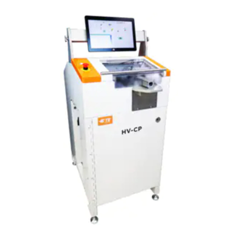
TE Connectivity HV-CP User manual

TE Connectivity

TE Connectivity HV-CP User manual

TE Connectivity LJSU-4X Series User manual

TE Connectivity

TE Connectivity LJSU-4X Series User manual

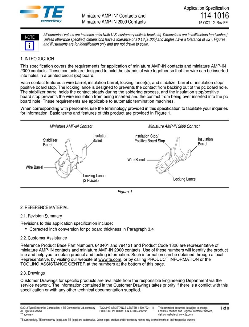
TE Connectivity Miniature AMP-IN User guide

TE Connectivity

TE Connectivity Miniature AMP-IN User guide

TE Connectivity AMPOWER 68361-1 User manual

TE Connectivity

TE Connectivity AMPOWER 68361-1 User manual

TE Connectivity D-150-Z Series Reference guide
TE Connectivity

TE Connectivity D-150-Z Series Reference guide

Popular Cables And Connectors manuals by other brands

Philips SWV3504W Specification sheet

Philips

Philips SWV3504W Specification sheet

Hive Plug user guide

Hive

Hive Plug user guide

Monoprice HD-140E3-3D-V2 manual

Monoprice

Monoprice HD-140E3-3D-V2 manual

Smart-M HDS4P user manual

Smart-M

Smart-M HDS4P user manual

Vanco EVSLIM14 manual

Vanco

Vanco EVSLIM14 manual

Stahl 8195 Series operating instructions

Stahl

Stahl 8195 Series operating instructions

Philips SWV4116S/10 user manual

Philips

Philips SWV4116S/10 user manual

Fujitsu PB-91469G-LS-256BGA user guide

Fujitsu

Fujitsu PB-91469G-LS-256BGA user guide

Lenze L-force EWS Mounting instructions

Lenze

Lenze L-force EWS Mounting instructions

HQ AVSPLIT-25 manual

HQ

HQ AVSPLIT-25 manual

Gefen DVI-144 user manual

Gefen

Gefen DVI-144 user manual

AUVIO Auvio 15-232 user guide

AUVIO

AUVIO Auvio 15-232 user guide

NEC 4xi NEC manual

NEC

NEC 4xi NEC manual

CommScope SYSTIMAX VisiPatch CPC5562 instruction sheet

CommScope

CommScope SYSTIMAX VisiPatch CPC5562 instruction sheet

Crestron C2N-TXM-C50 datasheet

Crestron

Crestron C2N-TXM-C50 datasheet

Gomax SP-5004IZM user manual

Gomax

Gomax SP-5004IZM user manual

Panasonic WV-QCA500A operating instructions

Panasonic

Panasonic WV-QCA500A operating instructions

SCHURTER 4795 Series Assembly instruction

SCHURTER

SCHURTER 4795 Series Assembly instruction

manuals.online logo
manuals.online logoBrands
  • About & Mission
  • Contact us
  • Privacy Policy
  • Terms and Conditions

Copyright 2025 Manuals.Online. All Rights Reserved.