User’s Guide
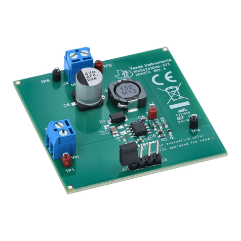
TPS54383 Step-Down Converter Evaluation Module User's
Guide
Table of Contents
1 Introduction.............................................................................................................................................................................3
1.1 Description......................................................................................................................................................................... 3
1.2 Applications........................................................................................................................................................................3
1.3 Features............................................................................................................................................................................. 3
2 TPS54383EVM Electrical Performance Specifications........................................................................................................4
3 Schematic................................................................................................................................................................................5
3.1 Sequencing Jump (JP3).....................................................................................................................................................6
3.2 Enable Jumpers (JP1 and JP2)......................................................................................................................................... 6
3.3 Test Point Descriptions.......................................................................................................................................................6
4 Test Set Up.............................................................................................................................................................................. 8
4.1 Equipment.......................................................................................................................................................................... 8
4.2 Equipment Setup................................................................................................................................................................9
4.3 Start Up / Shut Down Procedure...................................................................................................................................... 11
4.4 Output Ripple Voltage Measurement Procedure..............................................................................................................11
4.5 Control Loop Gain and Phase Measurement Procedure..................................................................................................11
4.6 Equipment Shutdown....................................................................................................................................................... 11
5 TPS54383EVM Typical Performance Data and Characteristic Curves.............................................................................12
5.1 Efficiency..........................................................................................................................................................................12
5.2 Line and Load Regulation................................................................................................................................................ 13
5.3 Output Voltage Ripple...................................................................................................................................................... 13
5.4 Switch Node..................................................................................................................................................................... 14
5.5 Control Loop Bode Plot (low line, VIN = 8 V).................................................................................................................... 14
5.6 Light Load Operation (revision A PCB only).................................................................................................................... 15
6 EVM Assembly Drawings and Layout.................................................................................................................................16
7 List of Materials.....................................................................................................................................................................22
8 Revision History................................................................................................................................................................... 22
List of Figures
Figure 3-1. TPS54383EVM Schematic........................................................................................................................................5
Figure 4-1. TPS54383EVM Recommended Test Set-Up............................................................................................................ 9
Figure 4-2. Tip and Barrel Measurement Technique (output ripple measurement using TP3 and TP4 or TP18 and TP19)..... 10
Figure 4-3. Control Loop Measurement Setup.......................................................................................................................... 10
Figure 5-1. TPS54383EVM Efficiency verse Load Current VIN =9.6-13.2 V, VOUT1 = 5.0 V IOUT1 = 0-2 A, VOUT2 = 3.3 V
IOUT2 = 0-2 A.......................................................................................................................................................................... 12
Figure 5-2. TPS54383EVM Output Voltage verse Load Current VIN =9.6-13.2 V, VOUT1 = 5.0 V IOUT1 = 0-2 A, VOUT2 =
3.3 V IOUT2 = 0-2 A.................................................................................................................................................................13
Figure 5-3. TPS54383EVM Output Voltage Ripple (VIN = 13.2 V, IOUT1 = IOUT2 = 2 A)............................................................. 13
Figure 5-4. TPS54383EVM Switching Waveforms VIN = 12 V, IOUT = 2 A Ch1: TP9 (SW1), Ch2: TP12 (SW2).......................14
Figure 5-5. TPS54383EVM Gain and Phase vs Frequency...................................................................................................... 14
Figure 6-1. TPS54383EVM Component Placement (viewed from top)..................................................................................... 16
Figure 6-2. TPS54383EVM Silkscreen (viewed from top)......................................................................................................... 17
Figure 6-3. TPS54383EVM Top Copper (viewed from top)....................................................................................................... 18
Figure 6-4. TPS54383EVM Bottom Copper (x-ray view from top).............................................................................................19
Figure 6-5. TPS54383EVM Internal 1 (x-ray view from top)......................................................................................................20
Figure 6-6. TPS54383EVM Internal 2 (x-ray view from top)......................................................................................................21
List of Tables
Table 2-1. Electrical Performance Specifications.........................................................................................................................4
Table 3-1. Test Point Descriptions............................................................................................................................................... 6
www.ti.com Table of Contents
SLUU285D – JULY 2007 – REVISED OCTOBER 2021
Submit Document Feedback
TPS54383 Step-Down Converter Evaluation Module User's Guide 1
Copyright © 2021 Texas Instruments Incorporated
