Toro MH-400SH2 User manual

FormNo.3418-742RevB
MH-400SH2orMH-400EH2
MaterialHandler
ModelNo.44931—SerialNo.401252001andUp
ModelNo.44954—SerialNo.401252001andUp
Registeratwww.Toro.com.
OriginalInstructions(EN)*3418-742*B

ThisproductcomplieswithallrelevantEuropean
directives,fordetailspleaseseetheseparateproduct
specicDeclarationofConformity(DOC)sheet.
ElectromagneticCompatibility
Domestic:ThisdevicecomplieswithFCCrulesPart15.
Operationissubjecttothefollowingtwoconditions:(1)This
devicemaynotcauseharmfulinterferenceand(2)thisdevice
mustacceptanyinterferencethatmaybereceived,including
interferencethatmaycauseundesirableoperation.
Thisequipmentgeneratesandusesradiofrequencyenergyand
ifnotinstalledandusedproperly,thatis,instrictaccordance
withthemanufacturer'sinstructions,maycauseinterferenceto
radioandtelevisionreception.Ithasbeentypetestedandfound
tocomplywiththelimitsforaFCCClassBcomputingdevice
inaccordancewiththespecicationsinSubpartJofPart15of
FCCRules,whicharedesignedtoprovidereasonableprotection
againstsuchinterferenceinaresidentialinstallation.However,
thereisnoguaranteethatinterferencewillnotoccurina
particularinstallation.Ifthisequipmentdoescauseinterference
toradioortelevisionreception,whichcanbedeterminedby
turningtheequipmentoffandon,theuserisencouragedto
trytocorrecttheinterferencebyoneormoreofthefollowing
measures:Reorientthereceivingantenna,relocatetheremote
controlreceiverwithrespecttotheradio/TVantennaorplug
thecontrollerintoadifferentoutletsothatthecontrollerand
radio/TVareondifferentbranchcircuits.Ifnecessary,theuser
shouldconsultthedealeroranexperiencedradio/television
technicianforadditionalsuggestions.Theusermayndthe
followingbookletpreparedbytheFederalCommunications
Commissionhelpful:"HowtoIdentifyandResolveRadio-TV
InterferenceProblems".ThisbookletisavailablefromtheU.S.
GovernmentPrintingOfce,Washington,DC20402.StockNo.
004-000-00345-4.
FCCID:W7OMRF24J40MDME-BASE,
OA3MRF24J40MA-HANDHELD
IC:7693A-24J40MDME-BASE,7693A-24J40MA-HANDHELD
Operationissubjecttothefollowingtwoconditions:(1)this
devicemaynotcauseinterference,and(2)thisdevicemust
acceptanyinterference,includinginterferencethatmaycause
undesiredoperationofthedevice.
JapanElectromagneticCompatibilityCertication
Handheld:
RF2CAN:
MexicoElectromagneticCompatibilityCertication
Handheld:
RF2CAN:
KoreaElectromagneticCompatibilityCertication(Decal
providedinseparatekit)
Handheld:
RF2CAN:
SingaporeElectromagneticCompatibilityCertication
Handheld:TWM-240004_IDA_N4020–15
RF2CAN:TWM-240005_IDA_N4024–15
MoroccoElectromagneticCompatibilityCertication
AGREEPARL’ANRTMAROC
Numerod’agrement:MR14079ANRT2017
Delivred’agrement:29/05/2017
WARNING
CALIFORNIA
Proposition65Warning
Useofthisproductmaycauseexposure
tochemicalsknowntotheStateof
Californiatocausecancer,birthdefects,
orotherreproductiveharm.
Introduction
Thismachineisintendedtobeusedbyprofessional,
hiredoperatorsincommercialapplications.Itis
primarilydesignedfortransporting,metering,and
dispersingmaterials,underarangeofmoisture
conditions,withoutcloggingordrasticallyaffecting
thedispersion.Usingthisproductforpurposesother
thanitsintendedusecouldprovedangeroustoyou
andbystanders.
Visitwww.T oro.comforproductsafetyandoperation
trainingmaterials,accessoryinformation,helpnding
adealer,ortoregisteryourproduct.
Wheneveryouneedservice,genuineT oroparts,or
additionalinformation,contactanAuthorizedService
DealerorToroCustomerServiceandhavethemodel
andserialnumbersofyourproductready.Figure1
identiesthelocationofthemodelandserialnumbers
ontheproduct.Writethenumbersinthespace
provided.
©2019—TheToro®Company
8111LyndaleAvenueSouth
Bloomington,MN554202
Contactusatwww.Toro.com.
PrintedintheUSA
AllRightsReserved

Important:Withyourmobiledevice,youcan
scantheQRcode(ifequipped)ontheserial
numberdecaltoaccesswarranty,parts,andother
productinformation.
g234791
Figure1
1.Modelandserialnumberlocation
ModelNo.
SerialNo.
Thismanualidentiespotentialhazardsandhas
safetymessagesidentiedbythesafety-alertsymbol
(Figure2),whichsignalsahazardthatmaycause
seriousinjuryordeathifyoudonotfollowthe
recommendedprecautions.
g000502
Figure2
Safety-alertsymbol
Thismanualuses2wordstohighlightinformation.
Importantcallsattentiontospecialmechanical
informationandNoteemphasizesgeneralinformation
worthyofspecialattention.
3

Contents
Safety.......................................................................5
GeneralSafety...................................................5
SafetyandInstructionalDecals..........................5
Setup........................................................................9
1InstallingtheHitch.........................................10
2InstallingtheWeightCase..............................10
3AdjustingtheMirror.........................................11
4WiringandInstallingtotheTow
Vehicle..........................................................12
5InstallingtheEHWirelessControlMounting
BracketontheTowVehicle............................13
6InstallingthePendantSwitch.........................14
7AssemblingtheHandheldRemote.................15
8AttachingtheHydraulicstotheTow
Vehicle..........................................................15
9Attachingthe7-pinCoiledPower
Cable............................................................16
10SettingtheElectricBrake
Adjustments..................................................16
ProductOverview...................................................17
Controls...........................................................17
Specications..................................................18
Attachments/Accessories.................................18
BeforeOperation.................................................19
BeforeOperationSafety...................................19
ConnectingtheMachinetotheTow
Vehicle..........................................................19
DuringOperation.................................................21
DuringOperationSafety...................................21
SlopeSafety.....................................................22
TurningtheMachinePowerOn/Off...................23
OperatingtheHydraulicControlValves.............23
OperatingtheHydraulicControlsand
OptionsonEHModels..................................24
OperatingtheFloorandOption.........................32
SettingthePreset1,2,and3Buttons................34
LoadingMaterial...............................................35
UnloadingMaterial............................................35
UsingtheTwinSpinner.....................................36
SettingUptheCrossConveyor/Swivel..............41
OperatingtheCrossConveyor..........................43
OperatingtheSwivelKit....................................44
AfterOperation....................................................45
AfterOperationSafety......................................45
DisconnectingtheMachinefromtheTow
Vehicle..........................................................45
Maintenance...........................................................46
MaintenanceSafety..........................................46
Pre-MaintenanceProcedures...........................46
Lubrication........................................................46
SafetyChecks..................................................47
HydraulicSystemSafety...................................48
HydraulicSystemMaintenance........................48
ChangingTires.................................................48
TrackingtheConveyorBelt...............................49
TensioningtheConveyorBelt...........................49
ChangingtheConveyorBelt.............................50
AdjustingtheConveyorDriveChain..................52
MaintainingtheElectricBrakes.........................52
Storage...................................................................54
Troubleshooting......................................................55
CheckingFaultCodes(EHModels
Only).............................................................55
HandheldRemoteMessages(EHModels
Only).............................................................57
4

Safety
GeneralSafety
Thisproductiscapableofcausingpersonalinjury.
Alwaysfollowallsafetyinstructionstoavoidserious
personalinjury.
•Readandunderstandthecontentsofthis
Operator’sManualbeforeusingthismachine.
Ensurethateveryoneusingthisproductknows
howtouseitandunderstandsthewarnings.
•Donotputyourhandsorfeetnearmoving
componentsofthemachine.
•Donotoperatethemachinewithoutallguards
andothersafetyprotectivedevicesinplaceand
workingonthemachine.
•Keepthemachineawayfrombystanderswhileit
ismoving.
•Keepchildrenoutoftheoperatingarea.Never
allowchildrentooperatethemachine.
•Parkthemachineonalevelsurface;engagethe
parkingbrake;shutoffthetraction-unitengine;
removethekey;andwaitforallmovementtostop
beforeservicingoruncloggingthemachine.
Improperlyusingormaintainingthismachinecan
resultininjury.Toreducethepotentialforinjury,
complywiththesesafetyinstructionsandalways
payattentiontothesafety-alertsymbol,which
meansCaution,Warning,orDanger—personalsafety
instruction.Failuretocomplywiththeseinstructions
mayresultinpersonalinjuryordeath.
SafetyandInstructionalDecals
Safetydecalsandinstructionsareeasilyvisibletotheoperatorandarelocatednearanyarea
ofpotentialdanger.Replaceanydecalthatisdamagedormissing.
decal119-6823
119-6823
SHmodelsonly
1.Reverseconveyorbelt4.Raisehopper
2.Advanceconveyorbelt5.Optionon
3.Lowerhopper
93-9899
decal93-9899
93-9899
1.Crushinghazard—installthecylinderlock.
decal119-6838
119-6838
1.Entanglementhazard,belt—stayawayfrommovingparts,
keepallguardsandshieldsinplace.
decal119-0217
119-0217
1.Warning—shutofftheengine;stayawayfrommovingparts;
keepallguardsandshieldsinplace.
decal115-2047
115-2047
1.Warning—donottouchthehotsurface.
5

decal119-6819
119-6819
1.Spinnerspeedpercentage2.Beltspeedpercentage
decal93-9852
93-9852
1.Warning—readtheOperator’sManual.2.Crushinghazard—installthecylinderlock.
decal119-6836
119-6836
1.ReadtheOperator'sManual.
2.Locateweightsothatrearoftheweightcaseis28in(71
cm)fromthefrontfaceofhitchtube.
decal119-6833
119-6833
1.ReadtheOperator'sManual.
2.Maximumloadweight11,800lb(5.352kg);vehicleweight
3,000lb(1,361kg),Maximumgrossvehicleweight14,800
lb(6,713kg)
decal131-6766
131-6766
Model44954Only
1.7.5A3.Electricalaccessory—15A
2.7.5A4.TEC-2403—2A
6

decal119-6806
119-6806
1.Warning—readtheOperator'sManual.4.Warning—shutofftheengine,removethekey,andreadthe
Operator'sManualbeforeperformingmaintenance.
2.Warning—alloperatorsshouldbetrainedbeforeoperating
themachine.
5.Warning—donotcarrypassengers.
3.Thrownobjecthazard—keepbystandersaway.6.Warning—stayawayfrommovingparts;keepallguardsand
shieldsinplace.
decal119-6835
119-6835
1.ReadtheOperator'sManual.
2.Donotstorethejackonrearleg.
decal119-6869
119-6869
1.Tailgateheightadjustment
decal119-6822
119-6822
Model44931Only
1.Belt
2.On
3.Off
decal119-6832
119-6832
Model44954Only
1.Adjustoorspeed
2.Lowerthehopper
3.Raisethehopper
4.Adjustspinnerspeed
7

decal119-6812
119-6812
1.Tippinghazard—donotturnfast;turnslowly;whenthe
hopperisempty,donotgofasterthan15mph(24kph);
whenthehopperisloaded,moveslowly;whenmovingover
roughterrain,moveslowly.
decal119-6863
119-6863
1.Towafullhopperinthe
loweredposition;donot
towaloweredhopperwith
thespinnerattachedinthe
loweredposition.
3.Towanemptyhopperin
theraisedposition;tow
anemptyhopperwitha
spinnerattachedinthe
raisedposition;donottow
afullhopperintheraised
position;donottowafull
hopperwiththespinner
attachedintheraised
position.
2.Towthefullhopperin
themiddlepositionwith
thespinnerattachedand
active.
8

Setup
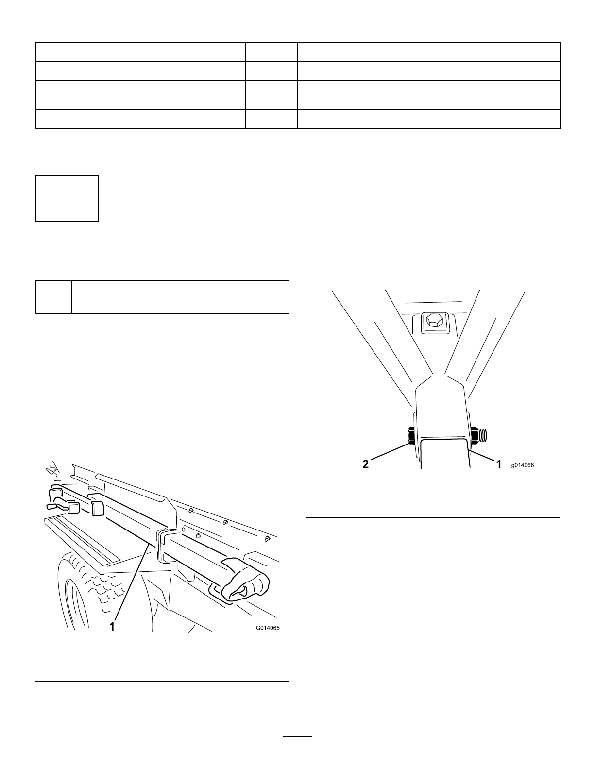
LooseParts
Usethechartbelowtoverifythatallpartshavebeenshipped.
ProcedureDescriptionQty.Use
Bolt(1x6-1/2inches)2
1Locknut(1inch)2Installthehitch.
2Nopartsrequired–Installtheweightcase.
3Nopartsrequired–Adjustthemirror.
Footcontroller1
Brakecontroller1
Harnessassembly1
Socketbracket1
Screw(5/16x1inch)4
Nut(5/16inch)4
Wiresplices6
Cabletie10
Bolt(#10x7/8inch)2
Nut(#10)2
4
Hoseclamp1
Installthewiringtothetowvehicle.
Mountingbracketassembly1
Backingplate1
Flangeheadbolt(5/16x1-1/2inches)4
5Flangeheadlocknut(5/16inch)4
InstalltheEHwirelesscontrolmounting
bracketonthetowvehicle(Model44954
only).
Pendantswitch1
6SHwireharness1Installthependantswitch.
Handheldremote1
AAbatteries4
Magneticbracket1
7Screws,small6
Assemblethehandheldremote.
8Nopartsrequired–Attachthehydraulicstothetowvehicle.
97-pincoiledpowercable1Attachthe7-pincoiledpowercable.
10Nopartsrequired–Settheelectricbrakeadjustments.
9
MediaandAdditionalParts
DescriptionQty.Use
Operator'sManual1Readthemanualbeforeoperatingthemachine.
DeclarationofConformity1TheDeclarationofConformityservesasEUproofof
certication.
Attachmentclamps2Usetomountattachments.
Note:Determinetheleftandrightsidesofthe
machinefromthenormaloperatingposition.
1
InstallingtheHitch
Partsneededforthisprocedure:
2Bolt(1x6-1/2inches)
2Locknut(1inch)
Procedure
1.Locateandremovetheloosepartsboxshipped
onthefender.
2.Removetherearsupportlegfromtheshipping
positionandplaceitinthedownposition.
3.Removethehitchfromtheshippingposition
bycuttingbothstrapssecuringthehitchto
thefender(Figure3).Removebothmounting
bracketsfromthefenderanddiscard.
g014065
Figure3
1.Removehitchfromshippingposition
Note:2peoplearerequiredtoremovethehitch
assembly.
4.Slidethehitchtubetongueintoplaceatthefront
ofthemachine.Ensurethatthejackmounting
bracketfacesouttowardstheleftside.
5.Placeabolt(1x6-1/2inchrd)throughtheframe
andhitchtubeandsecureitwithalocknut
(Figure4).Torquethelocknutto976to1,193
N-m(720to880ft-lb).
6.Placeabolt(1x6-1/2inches)throughthetopof
theframeanddownthroughthehitchtubeand
secureitwithalocknut(Figure4).Torquethe
locknutto976to1,193N-m(720to880ft-lb).
g014066
Figure4
1.Hitchtube2.Mountingboltandnut
7.Removethejackassemblyfromtherearleg.
Installthejackassemblyontothehitchtube,
placingthepinhorizontally.
Note:Donotplacethepinthroughthetophole
ofthejack,oryouwillnotbeabletoremovethe
pinwhentheweightcaseissecuredtothehitch.
10

2
InstallingtheWeightCase
NoPartsRequired
Procedure
1.Removetheweightsfromtheweightcase.
2.Removethebolts(1/2x5-1/2inch)fromthe
mountingbracketholdingtheweightcase.
Discardthemountingbrackets(Figure5).
g014067
Figure5
1.Weightcase2.Weightcasemounting
bracket
3.Positiontheweightcaseonthehitch,asfar
forwardaspossible.
4.Mounttheweightcasetothehitchwith2bolts
(1/2x5-1/2inch)andlocknuts.T orquethe
locknutsto91to112N-m(67to83ft-lb).
5.Filltheweightcasewiththeweightsandinstall
thebarandpin(Figure6).
g014069
Figure6
1.Fillweightcase
3
AdjustingtheMirror
NoPartsRequired
Procedure
Themirrormountedonthefrontofthehopperallows
youtomonitortheloadandthespreadingaction.
Checkthemirrorfrequentlytomonitortheoperation
ofthemachine.
Adjustthemirror(Figure7)sothatyoucanviewthe
insideofthehopperfromtheoperatorposition.
11
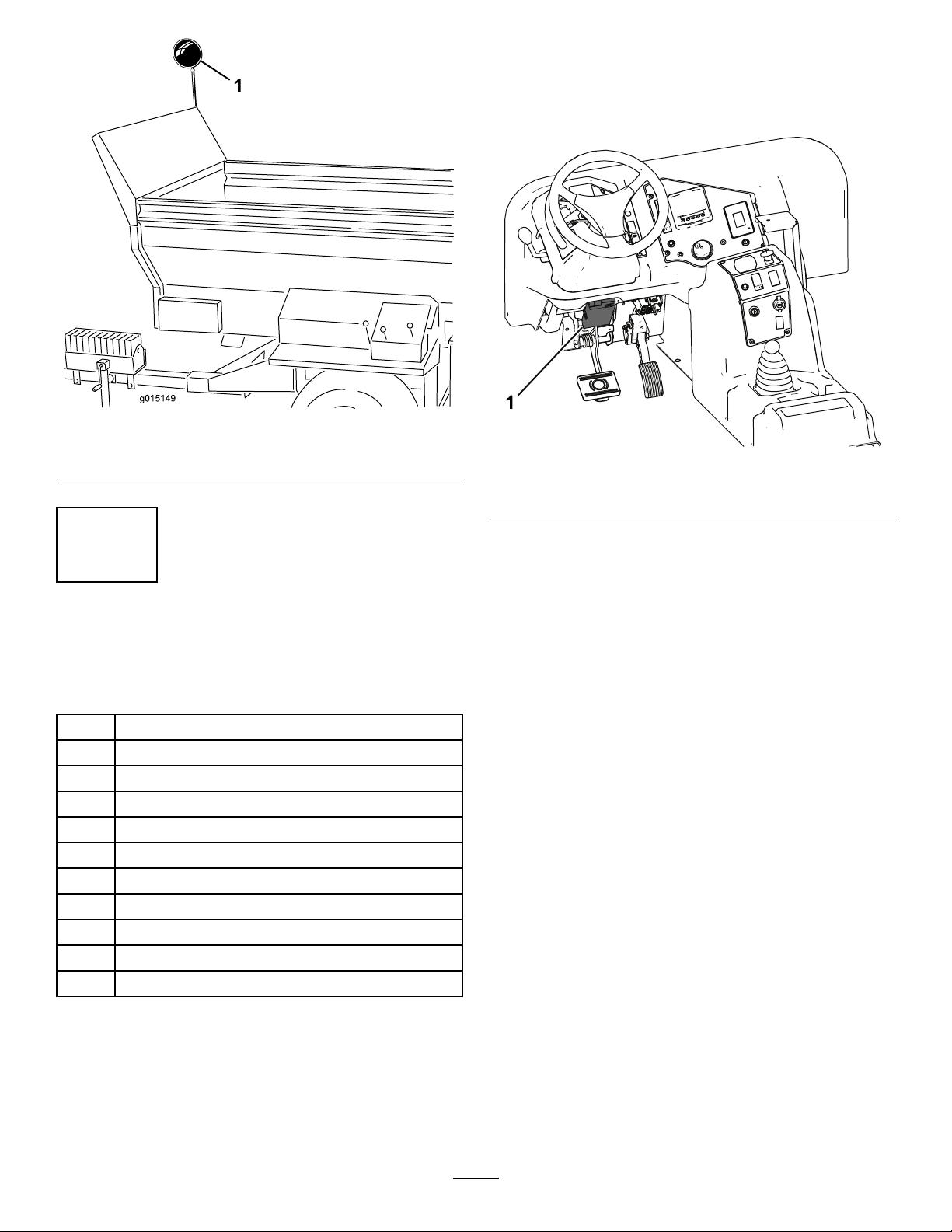
g015149
Figure7
1.Mirror
4
WiringandInstallingtothe
TowVehicle
Partsneededforthisprocedure:
1Footcontroller
1Brakecontroller
1Harnessassembly
1Socketbracket
4Screw(5/16x1inch)
4Nut(5/16inch)
6Wiresplices
10Cabletie
2Bolt(#10x7/8inch)
2Nut(#10)
1Hoseclamp
OutcrossTractionUnit
Mountthebrakecontroller(Figure8)tothelowerleft
areaofthedashboardwiththe2bolts(#10x7/8inch)
andnuts(#10).
ConnecttheOutcrosswireharnessconnectortothe
brakecontrollerconnector.
RefertotheOutcrosstractionunitOperator’sManual
foradditionalmountingandoperatinginstructions.
g235379
Figure8
1.Brakecontroller
Tractor
Note:Layouttheharnessonthetractortodetermine
themountinglocationsoftheharnesscomponents.
Cabletiesaresuppliedtoretainanysurpluscable
lengths.Also,wiresplicesareprovidedifthelength
oftheharnesshastobealtered(shortenedor
lengthened).Heattheshrinkconnectorsuntilthey
shrinktightontothewires.
Important:Iflengthisaddedtotheharness,
makesuretousethepropergaugewire.
1.Mountthesocketbrackettotherearofthetow
vehiclewith2bolts(5/16x1inch)andnuts.
2.Routethewireharnessconnectorthroughthe
holetothesocket.Slidethebootdownthe
harnessiftheconnectordoesnotgothrough
thehole.
3.Boltthewireharness,withthesocketconnector,
totherearofthesocketbracketwith2bolts
(5/16x1inch)andnuts.
4.Routetheharnessalongthetowvehicle.
5.Mountthebrakecontrollertothetractordashor
thefenderwiththe2bolts(#10x7/8inch)and
nuts(#10).
6.Usingthehoseclamp,securethefootcontroller
tothepadonthetowvehiclebrakepedal.
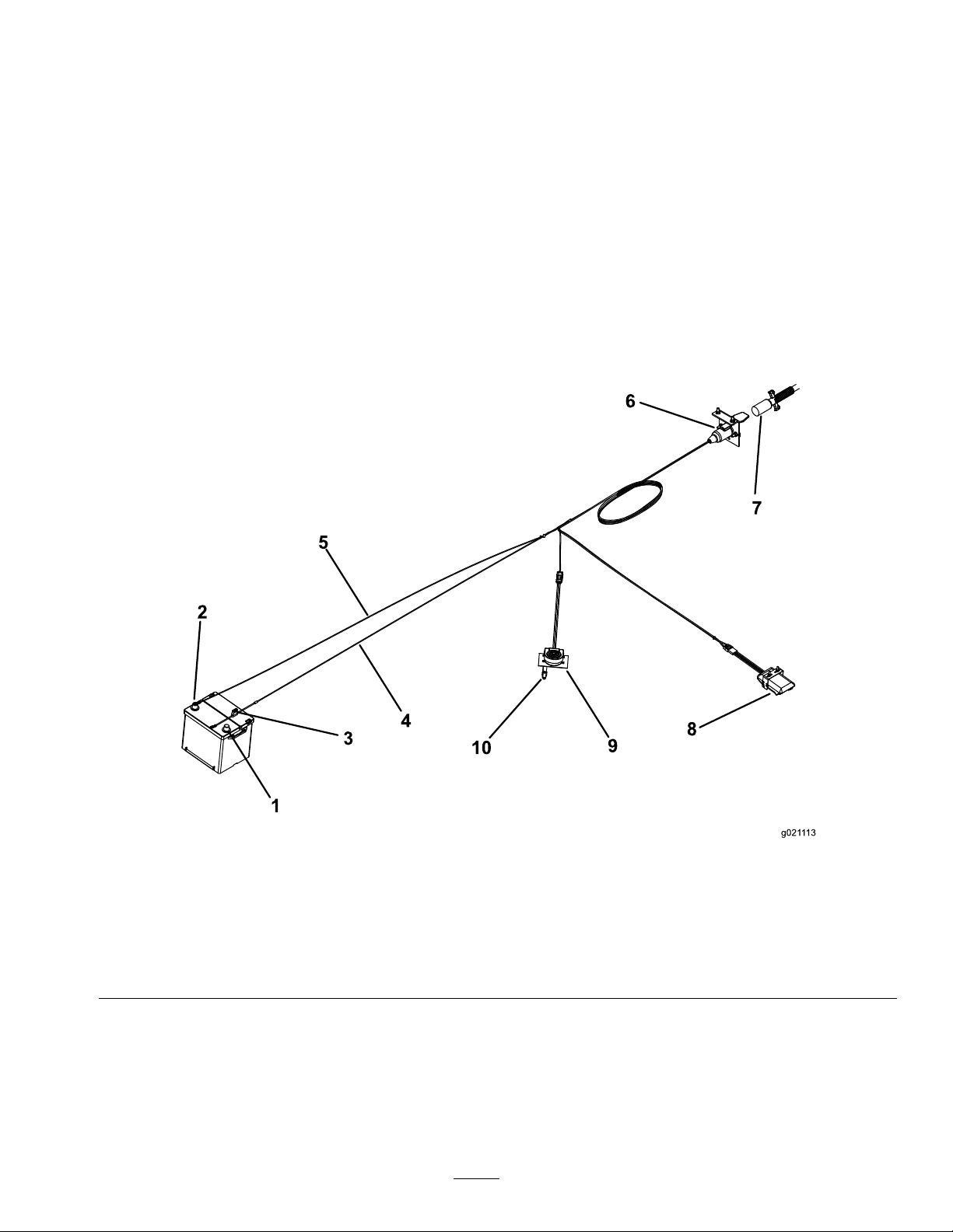
7.Connecttheharnesstothecomponents(Figure
9)asfollows:
12
A.Plugtheshorterwirefromtheharnessinto
thefootcontrollerwireconnector.
B.Connectthelongerwirefromtheharnessto
thebrakecontrollerwireconnector.
C.Select1ofthefollowingprocedureswhen
connectingtheringterminalwire,withthe
fuse,tothepositivebatteryterminal.
•Tohavethebrakecontrollerpowered
onlywhenthetowvehicleison,attach
theringterminalwire,withthefuse,to
anopenauxiliarypowersourcethathas
aratingof15Aormore.Usea10Afuse
fora2wheelbrakesystemanda15A
fusefora4wheelbrakesystem.
Note:Theringterminalmayneedto
beremovedandadifferentterminalend
mayneedtobeattachedtomatchthe
auxiliarypowersourceconnection.
•Tohavethebrakecontrolleralways
powered,attachtheringterminalwire,
withthefuse,tothepositivebattery
terminal.
Note:Ifthetowvehicleistobestored
foranextendedperiod,removethefuse
fromthebrakecontrollerwireharness
ordisconnectthewireharnessfromthe
brakecontroller.Thiswillpreventthe
batteryfrombeingdrained
D.Connecttheotherringterminalwire,
withoutthefuse,tothenegative(-)battery
terminal.
g021113
Figure9
1.Positivebatteryterminal(+)6.Socketconnector
2.Negativebatteryterminal(-)7.Powercable
3.Fuse8.Brakecontroller
4.Wireharness(+)9.Footcontroller
5.Wireharness(–)10.Hoseclamp
8.Securetherubberboottotheconnectorandto
thewireharnesswithacabletie.
9.Securealllooseharnesswireswithcableties.
10.A10Afuseisincludedintheharness.Ifusing
a4wheelbrakekit,replacethe10Afusewith
theprovided15Afuse.
13

5
InstallingtheEHWireless
ControlMountingBracket
ontheTowVehicle
Model44954Only
Partsneededforthisprocedure:
1Mountingbracketassembly
1Backingplate
4Flangeheadbolt(5/16x1-1/2inches)
4Flangeheadlocknut(5/16inch)
Procedure
1.Fortowvehiclemounting,determinean
appropriatelocationforthehandheldremote
mountingbracket.Thesurfaceshouldbeat
andsolid.
2.Usingthebackingplateasatemplate,locate,
mark,anddrill4holes(11/32inchdiameter)in
thetowvehiclemountingsurface.
3.Attachthemountingbracketandbackingplate
with4angeheadbolts(5/16x1-1/2inch)and
angelocknuts(Figure10andFigure11).
g028873
Figure10
1.Handheldremote3.Mountingbolts
2.EHhandheldremote
mount
g014103
Figure11
1.EHhandheldremotebackingplate
Note:Also,thewirelessremotemagnetwillstickto
anymetalcomponent.
6
InstallingthePendant
Switch
Model44931Only
Partsneededforthisprocedure:
1Pendantswitch
1SHwireharness
Procedure
Plugtheon/offpendantswitch(4prongend)intothe
socketatthefrontleftcornerofthemachine(Figure
12).
14

g014074
Figure12
1.On/offpendantswitch
Important:Alwaysremovetheon/offpendant
switchcordordisconnectthepowersupplywire
whenthemachineandtowvehiclearenotinuse.
Otherwise,thetowvehiclebatterywilllosepower.
7
AssemblingtheHandheld
Remote
Model44954Only
Partsneededforthisprocedure:
1Handheldremote
4AAbatteries
1Magneticbracket
6Screws,small
Procedure
1.Removetherubberbandssecuringtheremote
halvestogether,andremovethebackcover.
2.Plugeachbatteryintoaterminalcradle
observingproperpolarity.(Ifthebatteries
areimproperlyinstalled,theunitwillnotbe
damaged,butitwillfailtooperate.)Thecradle
isembossedwithpolaritymarkingsforeach
terminal(Figure13).
g028875
Figure13
1.Rubberseal3.Handheldremote
2.Steelgasket4.4AAbatteries
3.Ensurethatthesteelgasketandrubbersealare
seatedinthechannelintheremoteandsetthe
backcoverinplace(Figure13).
4.Securethecoverwith6screws(Figure13)and
torquethemto1.5to1.7N-m(13to15in-lb).
5.Installthehandheldremoteintothemagnetic
remotebracket,slidethehalvestogetherto
securetheremote,andtightentheboltinthe
magnet(Figure14).
g028874
Figure14
1.Handheldremote3.Boltinthemagnet
2.Magneticremotebracket
15

8
AttachingtheHydraulicsto
theTowVehicle
NoPartsRequired
Procedure
Note:Thetowvehiclemustbeequippedwithan
opencenterauxiliaryhydraulicvalve.
Forbestresults,useatowvehiclewithaxed
displacementhydraulicpumpwithapoweroutput
of138bar@38L/min(2,000psi@10gal/min).
Performancewillbereducedifthepumpoutputisless.
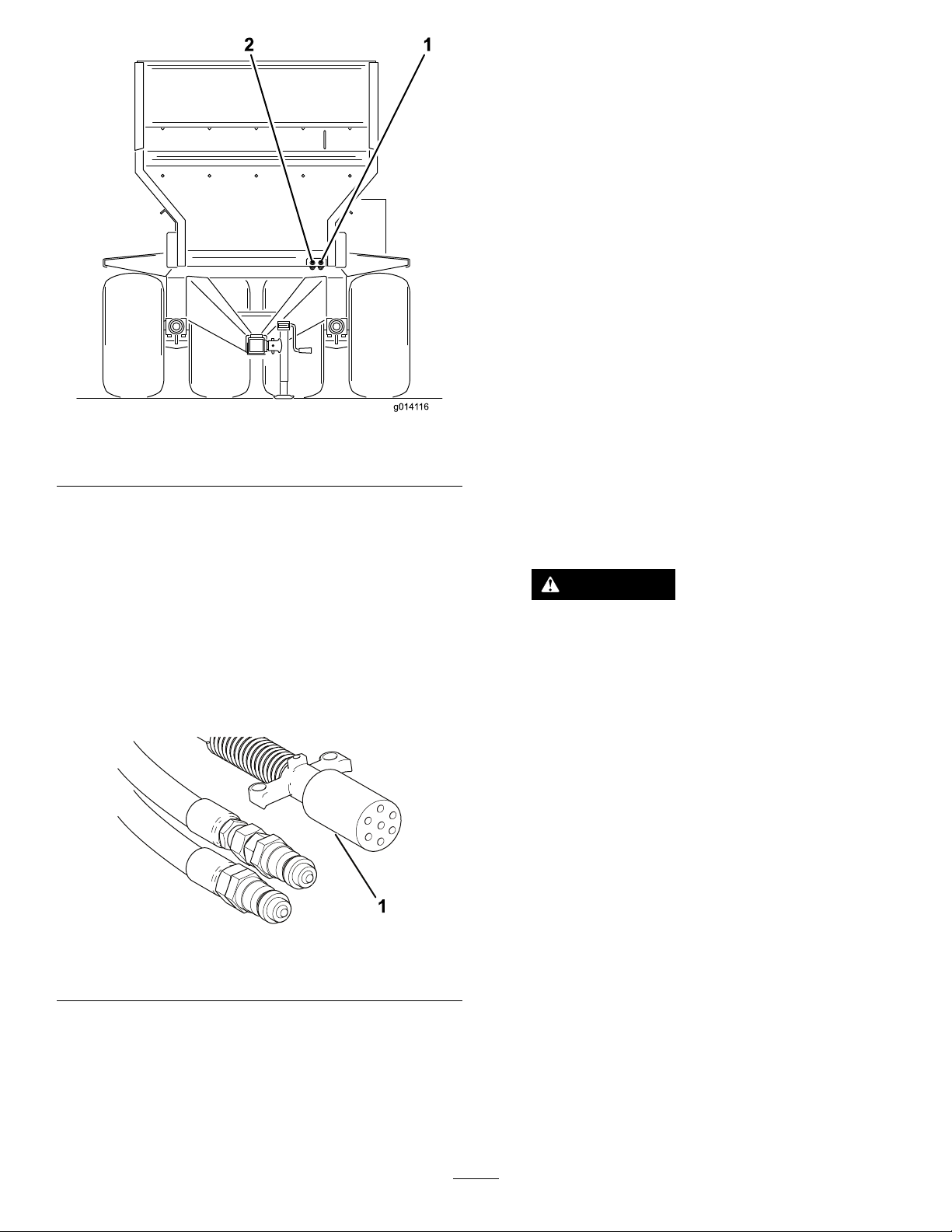
Connectthe2hydraulichosesfromthemachinetothe
towvehicle.Facingthefrontofthemachine,connect
therighthosetothepressuresideandthelefthoseto
thereturnside(Figure15).Thereturnhosehasanin
line1waycheckvalve.Also,thereisanarrowonthe
checkvalvewhichshouldfacetowardthetowvehicle.
g014116
Figure15
1.Pressurein2.Returnout
Important:Donotallowthehydraulichoses
andthepowercabletodragonthegroundwhen
operatingthemachine.Avoidlocationswhere
theycouldbecomepinchedorcut.
9
Attachingthe7-pinCoiled
PowerCable
Partsneededforthisprocedure:
17-pincoiledpowercable
Procedure
Attachthe7-pincoiledpowercabletotheMH-400
materialhandler.
Attachthe7-pincoiledpowercabletothetowvehicle.
10
SettingtheElectricBrake
Adjustments
NoPartsRequired
Procedure
Beforeoperatingthemachineforthersttime,the
electricbrakesmustbesynchronizedtothetow
vehicle’sbrakes(sothattheyoperateatthesame
time).
Themachineandthetowvehiclewillseldomhavethe
correctamperageowtothebrakemagnetstoprovide
comfortable,safebraking.Changingtheloadweight,
aswellasunevenalternatorandbatteryoutput,can
resultinunstablecurrentowtothebrakemagnets.
TheBrakeControlcompensatesfortrailerload
variationsbylimitingthemaximumtorqueoutput
ofthebrakesbyaddingdroppingresistanceinthe
electricalcontrolline.Whentowingatrailerloadedto
brakeratedcapacity,theBrakeControlmustbesetat
maximumbraking.Whenpullinganemptyorpartially
loadedtrailer,theBrakeControlmustbesetbetween
maximumandminimumbrakingatapositionjust
beforethepointatwhichtrailertireskiddingoccurs
whenactuatingthehandcontrolfullyon.Failureto
installandusetheElectricBrakeControlwillresultin
excessivebraketorquewhenstoppingatrailerloaded
tolessthanbrakecapacity.
16

ProductOverview
Controls
HydraulicControlValves(SH
Model44931)
g014117
Figure16
1.Conveyorbeltdirection(leftcontrolvalve)
2.Raiseandlowermachine(centercontrolvalve)
3.Optionsonandoff(rightcontrolvalve)
4.Optionhydraulicquickconnectors
LeftValve
Theleftvalvecontrolsthemachineconveyorbelt
direction(Figure16).
CenterValve
Thecentervalveraisesandlowersthemachine
(Figure16).
RightValve
Therightvalvecontrolstheoption(Figure16).
OptionHydraulicQuickConnectors
Connecttheoptionhydraulichere(Figure16).
E-Stopbutton(EHModel44954)
Whennishedworkingwiththemachine,always
presstheE-STOPbutton(Figure17)todisablethe
electricalsystem.Whenbeginningworkwiththe
machineyoumustpulltheE-STOPbuttonbackout
beforeturningonthehandheldremote.
g234789
Figure17
1.E-STOPButton
DiagnosticLEDFunction(EH
Model44954)
AfteryoupulluptheE-STOPbutton,thediagnostic
LED(Figure18)willilluminateandremainonfor5
seconds,turnofffor5seconds,andthenwillbegin
ashingat3Hz(3ashesasecond)untilyouturnthe
handheldremoteon.Ifthelightturnsonfor5seconds
andthenstartsblinkingat10Hz(withorwithouta5
secondpause),thereisafaultwiththemachine;refer
toCheckingFaultCodes(EHModelsOnly)(page55).
Note:Ifyouhadthehandheldremoteonwhenyou
pulleduptheE-STOPbutton,thelightwillnotash
at3Hz(3ashespersecond)afterturningofffor5
seconds.
g234788
Figure18
1.DiagnosticLED
17

HandheldRemote(EHModel
44954)
g028671
Figure19
1.LCDdisplay11.Floorstop
2.RemotestatusLED12.Decreaseoorspeed
3.Allstart:startsoorand
option
13.Increaseoorspeed
4.On/Off14.Floorreverse
5.Store:savespreset
settings
15.Tiltbeddown
6.Preset116.Tiltbedup
7.Preset217.Optionstart
8.Preset318.Optionstop
9.Allstop:stopsallfunctions19.Increaseoptionspeed
10.Floorstart20.Decreaseoptionspeed
Specications
Weight1,721kg(3,794lb)
Radio
Frequency2.4GHz
MaxOutputPower19.59dBm
Attachments/Accessories
AselectionofToroapprovedattachmentsand
accessoriesisavailableforusewiththemachine
toenhanceandexpanditscapabilities.Contact
yourAuthorizedServiceDealerorauthorizedT oro
distributororgotowww.Toro.comforalistofall
approvedattachmentsandaccessories.
Toensureoptimumperformance,useonly
genuineTororeplacementpartsandaccessories.
Replacementpartsandaccessoriesmadebyother
manufacturerscouldbedangerous,andsuchuse
couldvoidtheproductwarranty.
18

Operation
BeforeOperation
BeforeOperationSafety
•Themachinehasdifferentbalance,weight,and
handlingcharacteristicscomparedtosomeother
typesoftowedequipment.Readandunderstand
thecontentsofthisOperator'sManualbefore
operatingthemachine.Becomefamiliarwithall
controlsandknowhowtostopquickly.
•Neverallowchildrentooperatethemachine.Do
notallowadultstooperatethemachinewithout
properinstructions.Onlytrainedandauthorized
personsshouldoperatethismachine.
•Keepallshieldsandsafetydevicesinplace.Ifa
shield,safetydeviceordecalisillegibleormissing,
repairorreplaceitbeforeoperatingthemachine.
•Themachineisdesignedonlyforoff-roaduse.
Themaximumrecommendedspeedis24km/h
(15mph)withoutaloadand13km/h(8mph)with
afullload.
•Tightenanyloosenuts,bolts,andscrewsto
ensurethatthemachineisinsafeoperating
condition.Ensurethatthemachinetongue
mountingpins,hitchpins,andtonguejackarein
placeandsecure.
•Donotmodifythisequipmentinanymanner.
•Thetongueistheareaonthemachinewherethe
hitchconnectstothetowvehicle.Theweightof
thetongueaffectsthestabilityofthemachine.
–Anegativeorpositivetongueweightcancause
injurywhenconnectingordisconnectingthe
machinetothetowvehicle.Wheninstalled,
ensurethatthejack-standsareproperly
engaged.
–Whentheweightofthetongueisforcedupinto
thehitchofthetowvehicle,thisproducesa
negativetongueweight.
Negativetongueweightmayalsoresultwhen
attachmentsaremountedontherearofthe
machine.
–Whentheweightofthetongueisforceddown
ontothehitchofthetowvehicle,thisproduces
apositivetongueweight.
•Neverattachthemachinetoorremovethe
machinefromthetractionunitifthereismaterialin
thehopper.Thetonguemayipup,causinginjury.
ConnectingtheMachineto
theTowVehicle
1.Connectthemachinehitchtothetowvehicle
usinga25mm(1inch)diametersafetyapproved
hitchpinandsafetyclip(notsupplied).
2.Adjustthehitchheightbyturningthejackstand
handletokeepthemachinelevel.
3.Lowerthehitchusingthejackstand.
4.Whenthefullweightofthemachinehasbeen
transferredtothetowvehicle’sdrawbarfrom
thejackstand,pullthepinholdingthejackstand
inplace.
5.Turnthejackstand90degreescounterclockwise
untilthebottomofthejackstandpointsto
therearofthemachine.Thisisthetraveling
position.
CAUTION
Raisethejacksintothetravelingposition
beforetowingthemachine.
Beforeoperatingthemachine,raisethe
frontjackandrearjackleg.Removethe
jackfromthejacklegandstoreitonthe
tongueduringoperation.
6.Connectthe2hydraulichosesfromthemachine
tothetowvehicle.Facingthefrontofthe
machine,connecttherighthosetothepressure
sideandthelefthosetothereturnside(Figure
20).Thereturnhosehasanin-lineone-way
checkvalve.Thearrowonthecheckvalve
shouldfacethetowvehiclereturnconnector.
19
g014116
Figure20
1.Pressurein2.Returnout
Important:Donotallowthehydrauliclines,
thepowercable,andthependantcablesto
dragonthegroundduringoperation.Avoid
locationswheretheycouldbecomepinched
orcut.
7.OnSHmodelsplacetheon/offpendantwithin
reachofthedriver’sseat.Ensurethattheswitch
isoff.
8.Connectthe7-pincoiledpowercabletothe
socketonthemachineandthetowvehicle
(Figure21).
g234790
Figure21
1.7-pincoiledpowercable
9.Checkthehydraulicoillevelinthetowvehicles
tankandaddmoretollit,ifnecessary;referto
thetowvehicleowner’smanual.
10.Testthehydraulicsbeforeoperatingthemachine
forthersttime.
11.Settheelectricbrakeasfollows:
•Beforeoperatingthemachineforthe
rsttime,theelectricbrakesmustbe
synchronizedtothetowvehicle’sbrakes(so
thattheyoperateatthesametime).
•Themachineandthetowvehiclewillseldom
havethecorrectamperageowtothe
brakemagnetstoprovidecomfortable,safe
braking.Changingtheloadweight,aswell
asunevenalternatorandbatteryoutput,can
resultinunstablecurrentowtothebrake
magnets.
•TheLoadControlcompensatesfortrailer
loadvariationsbylimitingthemaximum
torqueoutputofthebrakesbyadding
droppingresistanceintheelectricalcontrol
line.Whentowingatrailerloadedtobrake
ratedcapacity,theBrakeControlmustbe
setatmaximumbraking.Whenpullingan
emptyorpartiallyloadedtrailer,theBrake
Controlmustbesetbetweenmaximumand
minimumbrakingatapositionjustbefore
thepointatwhichtrailertireskiddingoccurs
whenactuatingthehandcontrolfullyon.
FailuretoinstallandusetheElectricBrake
Controlwillresultinexcessivebraketorque
whenstoppingatrailerloadedtolessthan
brakecapacity.
CAUTION
Ifyouhearanoisefromthetowvehicle
hydraulicsandthemachinecontrols
donotoperate,thehoseshavebeen
connectedincorrectlyandmustbe
reversed.
Note:Youmayhavetorelievethepressurein
thehosesofthemachineconnectingtothetow
vehicle,toensureacompletedconnection.
Important:Whenmakingsharpturns,
thehydraulichosesmaycontactthetow
vehiclewheels.Avoidmakingsharpturns,
ifnecessary,useabungeecord(arubber
strapwithhooksonbothends)topullback
thehosestowardthecenter.
Thecapabilitiesofthemachinemayvarydepending
onthesizeandtypeoftowvehicle.
•Forbestresults,useatowvehiclewithatleast
45hpand4-wheeldrive.Atowvehiclewithless
than45hpwilllimitwhereyoucangoandhow
muchpayloadyoucandeliver.Forexample,a27
hptowvehiclecantowafullyloadedmachineover
atterrain,butnotonsteephills.A4-wheel-drive
vehiclewillalsoimproveperformanceonhills.
•Withasmallertowvehicle,youmayneedto
reducethepayloadto2m3(2.6yd3)ofmaterial
forspreadingindifcultterrain.Anotheroptionis
20
Other manuals for MH-400SH2
1
This manual suits for next models
3
Table of contents
Other Toro Industrial Equipment manuals

Toro
Toro BRC-28 User manual

Toro
Toro OSMAC G3 Satellite User manual

Toro
Toro 60216C User manual

Toro
Toro 22590 User manual

Toro
Toro MH-400SH2 User manual

Toro
Toro 04246 User manual

Toro
Toro 110-5076 User manual

Toro
Toro LAC TM User manual

Toro
Toro Workman 07224-90001 Instruction Manual

Toro
Toro 301 High Lift User manual

Toro
Toro FM 330 User manual

Toro
Toro Greensmaster eFlex 1021 User manual

Toro
Toro Groundsmaster 3320 User manual

Toro
Toro MB TX 2500 User manual

Toro
Toro MB TX 2500 User manual

Toro
Toro Workman Topdresser 1800 User manual

Toro
Toro Ultra Buggy e2500 User manual

Toro
Toro 22340 User manual

Toro
Toro TX 1300 User manual


