Toro MH-400SH2 User manual

FormNo.3427-232RevD
MH-400SH2andMH-400EH2
MaterialHandler
ModelNo.44931—SerialNo.403350001andUp
ModelNo.44954—SerialNo.403350001andUp
Registeratwww.Toro.com.
OriginalInstructions(EN)*3427-232*D

ThisproductcomplieswithallrelevantEuropean
directives;fordetails,pleaseseetheseparateproduct
specicDeclarationofConformity(DOC)sheet.
ElectromagneticCompatibility
Domestic:ThisdevicecomplieswithFCCRulesPart15.
Operationissubjecttothefollowingtwoconditions:(1)This
devicemaynotcauseharmfulinterferenceand(2)thisdevice
mustacceptanyinterferencethatmaybereceived,including
interferencethatmaycauseundesirableoperation.
Thisequipmentgeneratesandusesradiofrequencyenergyand
ifnotinstalledandusedproperly,instrictaccordancewiththe
manufacturer'sinstructions,maycauseinterferencetoradio
andtelevisionreception.Ithasbeentypetestedandfoundto
complywithinthelimitsofaFCCClassBcomputingdevicein
accordancewiththespecicationsinSubpartJofPart15of
FCCRules,asstatedabove.However,thereisnoguarantee
thatinterferencewillnotoccurinaparticularinstallation.If
thisequipmentdoescauseinterferencetoradioortelevision
reception,whichcanbedeterminedbyturningtheequipmentoff
andon,theuserisencouragedtotrytocorrecttheinterference
byoneormoreofthefollowingmeasures:Reorientthereceiving
antenna,relocatetheremotecontrolreceiverwithrespecttothe
radio/TVantennaorplugthecontrollerintoadifferentoutletso
thatthecontrollerandradio/TVareondifferentbranchcircuits.If
necessary,theusershouldconsultthedealeroranexperienced
radio/televisiontechnicianforadditionalsuggestions.The
usermayndthefollowingbookletpreparedbytheFederal
CommunicationsCommissionhelpful:"HowtoIdentifyand
ResolveRadio-TVInterferenceProblems".Thisbookletis
availablefromtheU.S.GovernmentPrintingOfce,Washington,
DC20402.StockNo.004-000-00345-4.
FCCID:W7OMRF24J40MDME-Base,
OA3MRF24J40MA-HandHeld
IC:7693A-24J40MDME-Base,7693A-24J40MA-HandHeld
Operationissubjecttothefollowingtwoconditions:(1)this
devicemaynotcauseinterference,and(2)thisdevicemust
acceptanyinterference,includinginterferencethatmaycause
undesiredoperationofthedevice.
JapanElectromagneticCompatibilityCertication
Handheld:
RF2CAN:
MexicoElectromagneticCompatibilityCertication
Handheld:
RF2CAN:
KoreaElectromagneticCompatibilityCertication(Decal
providedinseparatekit)
Handheld:
RF2CAN:
SingaporeElectromagneticCompatibilityCertication
Handheld:TWM240007_IDA_N4021–15
RF2CAN:TWM-240005_IDA_N4024–15
MoroccoElectromagneticCompatibilityCertication
AGREEPARL’ANRTMAROC
Numerod’agrement:MR14092ANRT2017
Delivred’agrement:29/05/2017
WARNING
CALIFORNIA
Proposition65Warning
Useofthisproductmaycauseexposure
tochemicalsknowntotheStateof
Californiatocausecancer,birthdefects,
orotherreproductiveharm.
Introduction
Thismachineisintendedtobeusedbyprofessional,
hiredoperatorsincommercialapplications.Itis
primarilydesignedfortransporting,metering,and
dispersingmaterials.
Usingthisproductforpurposesotherthanitsintended
usecouldprovedangeroustoyouandbystanders.
Readthisinformationcarefullytolearnhowtooperate
andmaintainyourproductproperlyandtoavoid
injuryandproductdamage.Youareresponsiblefor
operatingtheproductproperlyandsafely.
Visitwww.Toro.comforproductsafetyandoperation
trainingmaterials,accessoryinformation,helpnding
adealer,ortoregisteryourproduct.
Wheneveryouneedservice,genuineT oroparts,or
additionalinformation,contactanAuthorizedService
DealerorToroCustomerServiceandhavethemodel
andserialnumbersofyourproductready.Figure1
identiesthelocationofthemodelandserialnumbers
ontheproduct.Writethenumbersinthespace
provided.
Important:Withyourmobiledevice,youcan
scantheQRcode(ifequipped)ontheserial
numberplatetoaccesswarranty,parts,andother
productinformation.
©2019—TheToro®Company
8111LyndaleAvenueSouth
Bloomington,MN554202
Contactusatwww.Toro.com.
PrintedintheUSA
AllRightsReserved

g234791
Figure1
1.Modelandserialnumberlocation
ModelNo.
SerialNo.
Thismanualidentiespotentialhazardsandhas
safetymessagesidentiedbythesafety-alertsymbol
(Figure2),whichsignalsahazardthatmaycause
seriousinjuryordeathifyoudonotfollowthe
recommendedprecautions.
g000502
Figure2
1.Safety-alertsymbol
Thismanualuses2wordstohighlightinformation.
Importantcallsattentiontospecialmechanical
informationandNoteemphasizesgeneralinformation
worthyofspecialattention.
3

Contents
Safety.......................................................................5
GeneralSafety...................................................5
SafetyandInstructionalDecals..........................5
Setup........................................................................9
1InstallingtheHitch.........................................10
2InstallingtheWeightCase..............................10
3AdjustingtheMirror.........................................11
4WiringandInstallingtotheTraction
Unit...............................................................12
5InstallingtheEHWirelessControl
MountingBracketontheTraction
Unit...............................................................14
6InstallingthePendantSwitch.........................14
7AssemblingtheHandheldRemote.................15
8AttachingtheHydraulicstotheTraction
Unit...............................................................16
9Connectingthe7-pinCoiledPower
Cable............................................................16
10SettingtheElectricBrake
Adjustments..................................................16
11AssemblinganOptionalAttachmentto
theMachine..................................................16
ProductOverview...................................................18
Controls...........................................................18
Specications..................................................20
Attachments/Accessories.................................20
BeforeOperation.................................................20
BeforeOperationSafety...................................20
SelectingaTractionUnit...................................21
ConnectingtheMachinetotheTraction
Unit...............................................................21
BeforeOperationsChecks................................23
DuringOperation.................................................23
DuringOperationSafety...................................23
SlopeSafety.....................................................24
UsingtheRear-JackLeg..................................25
SupportingtheFrontoftheMachinewiththe
Jack..............................................................27
StowingtheJack..............................................27
TowingtheMachine..........................................28
ElectricBrakeOperatingTips...........................28
TurningtheMachinePowerOn/Off...................28
OperatingtheHydraulicControlValves.............29
OperatingtheHydraulicControlsand
Options.........................................................30
CaringfortheHandheldRemote.......................35
ReplacingtheBatteriesintheHandheld
Remote.........................................................35
AssociatingtheHandheldRemotewiththe
Base..............................................................36
OperatingtheFloorandOptionUsingthe
HandheldRemote.........................................36
HandheldRemotePresetModes......................39
LoadingtheHopper..........................................39
UnloadingMaterial............................................40
OperatingtheOptionalAttachment...................40
AfterOperation....................................................41
AfterOperationSafety......................................41
DisconnectingtheMachinefromtheTraction
Unit...............................................................41
Maintenance...........................................................42
MaintenanceSafety..........................................42
RecommendedMaintenanceSchedule(s)...........42
Pre-MaintenanceProcedures..............................42
InstallingtheHydraulic-Cylinder
Support.........................................................42
Lubrication..........................................................43
GreaseSpecication........................................43
LubricatingtheBearingsandBushings.............43
DriveSystemMaintenance..................................44
CheckingtheTireandWheels..........................44
ChangingTires.................................................44
BrakeMaintenance.............................................45
InspectingtheElectricBrakes...........................45
AdjustingtheElectricBrakes............................45
InspectingtheBrakeShoesandLinings............46
BrakeCleaningandInspection.........................46
BrakeLubrication.............................................46
InspectingtheMagnets.....................................46
HydraulicSystemMaintenance...........................47
HydraulicSystemSafety...................................47
HydraulicFluidSpecication.............................47
CheckingtheHydraulicSystem........................47
OptionalAttachments...........................................48
CheckingtheOptionalAttachments..................48
MaintainingtheConveyorBelt..............................48
CheckingtheConveyorBeltandRollers...........48
AdjustingtheConveyorBeltTracking................48
AdjustingtheConveyorBeltTension.................49
ChangingtheConveyorBelt.............................49
AdjustingtheConveyorDriveChain
Tension.........................................................51
MaintainingtheHopperandRearGate.................52
CheckingtheConveyorSealsandRear
GateSeal......................................................52
CheckingtheRearGate...................................52
Cleaning..............................................................52
WashingtheMachine.......................................52
Storage...................................................................53
Troubleshooting......................................................54
CheckingFaultCodes......................................54
HandheldRemoteMessages...........................56
4

Safety
GeneralSafety
Thisproductiscapableofcausingpersonalinjury.
Alwaysfollowallsafetyinstructionstoavoidserious
personalinjury.
•Readandunderstandthecontentsofthis
Operator’sManualbeforeusingthismachine.
Ensurethateveryoneusingthisproductknows
howtouseitandunderstandsthewarnings.
•Donotputyourhandsorfeetnearmoving
componentsofthemachine.
•Donotoperatethemachinewithoutallguards
andothersafetyprotectivedevicesinplaceand
workingonthemachine.
•Keepthemachineawayfrombystanderswhileit
ismoving.
•Keepchildrenoutoftheoperatingarea.Never
allowchildrentooperatethemachine.
•Parkthemachineonalevelsurface;engagethe
parkingbrake;shutoffthetraction-unitengine;
removethekey;andwaitforallmovementtostop
beforeservicingoruncloggingthemachine.
Improperlyusingormaintainingthismachinecan
resultininjury.Toreducethepotentialforinjury,
complywiththesesafetyinstructionsandalways
payattentiontothesafety-alertsymbol,which
meansCaution,Warning,orDanger—personalsafety
instruction.Failuretocomplywiththeseinstructions
mayresultinpersonalinjuryordeath.
Youcanndadditionalsafetyinformationwhere
neededthroughoutthismanual.
SafetyandInstructionalDecals
Safetydecalsandinstructionsareeasilyvisibletotheoperatorandarelocatednearanyarea
ofpotentialdanger.Replaceanydecalthatisdamagedormissing.
decal119-6823
119-6823
SHmodelsonly
1.Reverseconveyorbelt4.Raisehopper
2.Advanceconveyorbelt5.Optionon
3.Lowerhopper
93-9899
decal93-9899
93-9899
1.Crushinghazard—installthecylinderlock.
decal119-6838
119-6838
1.Entanglementhazard,belt—stayawayfrommovingparts,
keepallguardsandshieldsinplace.
decal119-0217
119-0217
1.Warning—shutofftheengine;stayawayfrommovingparts;
keepallguardsandshieldsinplace.
5

decal119-6819
119-6819
1.Spinnerspeedpercentage2.Beltspeedpercentage
decal93-9852
93-9852
1.Warning—readtheOperator’sManual.2.Crushinghazard—installthecylinderlock.
decal119-6836
119-6836
1.ReadtheOperator'sManual.
2.Locateweightsothatrearoftheweightcaseis28in(71
cm)fromthefrontfaceofhitchtube.
decal119-6833
119-6833
1.ReadtheOperator'sManual.
2.Maximumloadweight11,800lb(5.352kg);vehicleweight
3,000lb(1,361kg),Maximumgrossvehicleweight14,800
lb(6,713kg)
decal131-6766
131-6766
Model44954Only
1.7.5A3.Electricalaccessory—15A
2.7.5A4.TEC-2403—2A
6

decal119-6806
119-6806
1.Warning—readtheOperator'sManual.4.Warning—shutofftheengine,removethekey,andreadthe
Operator'sManualbeforeperformingmaintenance.
2.Warning—alloperatorsshouldbetrainedbeforeoperating
themachine.
5.Warning—donotcarrypassengers.
3.Thrownobjecthazard—keepbystandersaway.6.Warning—stayawayfrommovingparts;keepallguardsand
shieldsinplace.
decal119-6835
119-6835
1.ReadtheOperator'sManual.
2.Donotstorethejackonrearleg.
decal119-6869
119-6869
1.Tailgateheightadjustment
decal119-6822
119-6822
Model44931Only
1.Belt
2.On
3.Off
decal119-6832
119-6832
Model44954Only
1.Adjustoorspeed
2.Lowerthehopper
3.Raisethehopper
4.Adjustspinnerspeed
7

decal119-6812
119-6812
1.Tippinghazard—donotturnfast;turnslowly;whenthe
hopperisempty,donotgofasterthan15mph(24kph);
whenthehopperisloaded,moveslowly;whenmovingover
roughterrain,moveslowly.
decal119-6863
119-6863
1.Towafullhopperinthe
loweredposition;donot
towaloweredhopperwith
thespinnerattachedinthe
loweredposition.
3.Towanemptyhopperin
theraisedposition;tow
anemptyhopperwitha
spinnerattachedinthe
raisedposition;donottow
afullhopperintheraised
position;donottowafull
hopperwiththespinner
attachedintheraised
position.
2.Towthefullhopperin
themiddlepositionwith
thespinnerattachedand
active.
decal133-8061
133-8061
8

Setup
LooseParts
Usethechartbelowtoverifythatallpartshavebeenshipped.
ProcedureDescriptionQty.Use
Bolt,1x6-1/2inches2
1Locknut,1inch2Installthehitch
2Nopartsrequired–Installtheweightcase.
3Nopartsrequired–Adjustthemirror.
Footcontroller1
Brakecontroller1
Harnessassembly1
Socketbracket1
Screw,5/16x1inch4
Nut,5/16inch4
Wiresplices6
Cabletie10
Bolt,#10x7/8inch2
Nut,#102
Hoseclamp1
4
Fuse(15A)1
WireandInstalltothetractionunit.
Mountingbracketassembly1
Backingplate1
Flangeheadbolt,5/16x1-1/2inch4
5Flangeheadlocknut,5/164
InstalltheEHwirelesscontrolmounting
bracketonthetractionunit(Model
44954only).
Pendantswitch1
6SHwireharness1Installthependantswitch.
Handheldremote1
AAbatteries4
Magneticbracket1
7Screws,small6
Assemblethehandheldremote.
8Nopartsrequired–Attachthehydraulicstothetractionunit.
97-pincoiledpowercable1Connectthe7-pincoiledpowercable.
10Nopartsrequired–Settheelectricbrakeadjustments.
11Quickattachmountingclamp2Assembleanoptionalattachmenttothe
machine.
9

MediaandAdditionalParts
DescriptionQty.Use
Operator'sManual1Readthemanualbeforeoperatingthemachine.
DeclarationofConformity1TheDeclarationofConformityservesasEUproofof
certication.
Attachmentclamps2Usetomountattachments.
Note:Determinetheleftandrightsidesofthe
machinefromthenormaloperatingposition.
1
InstallingtheHitch
Partsneededforthisprocedure:
2Bolt,1x6-1/2inches
2Locknut,1inch
Procedure
1.Locateandremovetheloosepartsboxshipped
onthefender.
2.Removetherearjacklegfromthestowed
positionandassemblethejackleginthevertical
position;refertoSupportingtheMachinewith
theRear-JackLeg(page25).
3.Removethehitchfromtheshippingposition
bycuttingbothstrapssecuringthehitchto
thefender(Figure3).Removebothmounting
bracketsfromthefenderanddiscard.
g014065
Figure3
1.Removehitchfromshippingposition
Note:Use2peopletoremovethehitch
assembly.
4.Slidethehitchtubetongueintoplaceatthefront
ofthemachine.Ensurethatthejackmounting
bracketfacesouttowardtheleftside.
5.Placeabolt(1x6-1/2inches)throughtheframe
andhitchtubeandsecureitwithalocknut
(Figure4).Torquethelocknutto976to1,193
N-m(720to880ft-lb).
6.Placeabolt(1x6-1/2inches)throughthetopof
theframeanddownthroughthehitchtubeand
secureitwithalocknut(Figure4).T orquethe
locknutto976to1,193N-m(720to880ft-lb).
g014066
Figure4
1.Hitchtube2.Mountingboltandnut
7.Removethejackfromtherear-jacklegand
installthejackontothehitchtube;referto
SupportingtheFrontoftheMachinewiththe
Jack(page27).
Note:Donotinsertthepinthroughthevertical
holeofthejack,oryouwillnotbeabletoremove
thepinwhentheweightcaseisinstalled.
10

2
InstallingtheWeightCase
NoPartsRequired
Procedure
1.Removetheweightsfromtheweightcase.
2.Removethebolts(1/2x5-1/2inches)from
themountingbracketholdingtheweightcase.
Discardthemountingbrackets(Figure5).
g014067
Figure5
1.Weightcase2.Weightcasemounting
bracket
3.Positiontheweightcaseonthehitch,asfar
forwardaspossible.
4.Mounttheweightcasetothehitchwith2bolts
(1/2x5-1/2inches)andlocknuts.Torquethe
locknutsto91to112N-m(67to83ft-lb).
5.Filltheweightcasewiththeweightsandinstall
thebarandpin(Figure6).
g014069
Figure6
1.Fillweightcase
3
AdjustingtheMirror
NoPartsRequired
Procedure
Themirrormountedonthefrontofthehopperallows
youtomonitortheloadandthespreadingaction.
Checkthemirrorfrequentlytomonitortheoperation
ofthemachine.
Adjustthemirror(Figure7)sothatyoucanviewthe
insideofthehopperfromtheoperatorposition.
11

g015149
Figure7
1.Mirror
4
WiringandInstallingtothe
TractionUnit
Partsneededforthisprocedure:
1Footcontroller
1Brakecontroller
1Harnessassembly
1Socketbracket
4Screw,5/16x1inch
4Nut,5/16inch
6Wiresplices
10Cabletie
2Bolt,#10x7/8inch
2Nut,#10
1Hoseclamp
1Fuse(15A)
SelectingaTractionUnit
Selectatractionunitthatmeetsthespecicationsand
tractionunitrecommendations;refertoSpecications
(page20)andSelectingaTractionUnit(page21).
InstallingtheBrakeController
OutcrossTractionUnits
1.Mountthebrakecontroller(Figure8)tothe
lowerleftareaofthedashboardwiththe2bolts
(#10x7/8inch)andnuts(#10).
g235379
Figure8
1.Brakecontroller
2.ConnecttheOutcrosswireharnessconnectorto
thebrakecontrollerconnector.
RefertotheOutcrosstractionunitOperator’s
Manualforadditionalmountingandoperating
instructions.
InstallingtheBrakeController
TractorTypeTractionUnits
Mountthebrakecontrollertothedashorthefender
ofthetractorwiththe2bolts(#10x7/8inch)and
nuts(#10).
InstallingtheWireHarnessand
BrakeController
Note:Layouttheharnessonthetractionunitto
determinethemountinglocationsoftheharness
components.Usecabletiestobundlesurpluscable
lengths.Also,usethewirespliceswhenalteringthe
harnesslength(shortenedorlengthened).Heatthe
shrinktheconnectorsuntiltheyaretighttothewires.
Important:Ifyouaddwiretotheharness,ensure
tousethepropergaugewire.
1.Mountthesocketbrackettotherearofthe
tractionunitwith2bolts(5/16x1inch)andnuts.
2.Routethewireharnessconnectorthroughthe
holetothesocket.
12

Iftheconnectordoesnotgothroughthehole,
slidethebootdowntheharness.
3.Boltthewireharness,withthesocketconnector,
totherearofthesocketbracketwith2bolts
(5/16x1inch)andnuts.
4.Routetheharnessalongthetractionunit.
5.Usethehoseclamptosecurethefootcontroller
tothepadonthebrakepedal.
6.Connecttheharnesstothecomponents(Figure
9)asfollows:
A.Plugtheshorterwirefromtheharnessinto
thefootcontrollerwireconnector.
B.Connectthelongerwirefromtheharnessto
thebrakecontrollerwireconnector.
C.Selectoneofthefollowingprocedureswhen
connectingtheringterminalwire(withthe
fuse)toapositiveelectricalsource:
•Tohavethebrakecontrollerpowered
onlywhenthetractionunitispowered
on,attachtheringterminalwire,with
thefuse,toanopenauxiliary-power
sourcethathasaratingof15Aormore.
Usea10Afusefora2wheelbrake
systemanda15Afusefora4wheel
brakesystem.
Note:Youmayneedtoremovethering
terminalandinstalladifferentterminal
typetomatchtheauxiliarypowersource
connection.
•Tohavethebrakecontrolleralways
powered,attachtheringterminalwire,
withthefuse,tothepositivebattery
terminal.
Note:Ifyoustorethetractionunitfor
anextendedperiod,removethefuse
fromthebrakecontrollerwireharness
ordisconnectthewireharnessfrom
thebrakecontroller.Thispreventsthe
batteryfromdischarging
D.Connecttheotherringterminalwire,
withoutthefuse,tothenegative(-)battery
terminal.
g021113
Figure9
1.Positivebatteryterminal(+)6.Socketconnector
2.Negativebatteryterminal(-)7.Powercable
3.Fuse8.Brakecontroller
4.Wireharness(+)9.Footcontroller
5.Wireharness(–)10.Hoseclamp
13
7.Securetherubberboottotheconnectorandto
thewireharnesswithacabletie.
8.Securealllooseharnesswireswithcableties.
9.Ifyouareusinga4wheelbrakekit,removethe
10ampfusefromthefuseholderandinsertthe
15ampfuse.
5
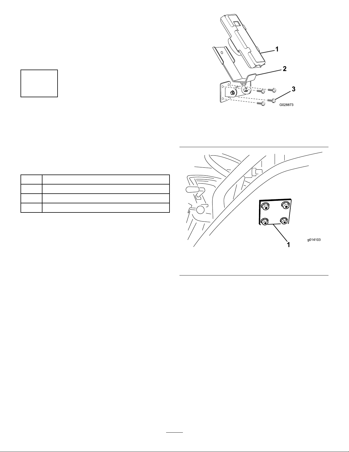
InstallingtheEHWireless
ControlMountingBracket
ontheTractionUnit
Model44954Only
Partsneededforthisprocedure:
1Mountingbracketassembly
1Backingplate
4Flangeheadbolt,5/16x1-1/2inch
4Flangeheadlocknut,5/16
Procedure
1.Fortractionunitmounting,determinean
appropriatelocationforthehandheldremote
mountingbracket.Thesurfaceshouldbeat
andsolid.
2.Usingthebackingplateasatemplate,locate,
mark,anddrill4holes(11/32inchdiameter)in
thetractionunitmountingsurface.
3.Attachthemountingbracketandbackingplate
with4angeheadbolts(5/16x1-1/2inches)
andangelocknuts(Figure10andFigure11).
g028873
Figure10
1.Handheldremote3.Mountingbolts
2.EHhandheldremote
mount
g014103
Figure11
1.EHhandheldremotebackingplate
Note:Thewirelessremotemagnetcansticktoany
metalcomponent.
14

6
InstallingthePendant
Switch
SHModels
Partsneededforthisprocedure:
1Pendantswitch
1SHwireharness
Procedure
Plugtheon/offpendantswitch(4prongend)intothe
socketatthefrontleftcornerofthemachine(Figure
12).
g014074
Figure12
1.On/offpendantswitch
Important:Alwaysunplugthependantswitch
cordordisconnectthepower-supplywire
whenthemachineandtractionunitarenot
used—otherwisethebatteryofthetractionunit
losespower.
7
AssemblingtheHandheld
Remote
EHModels
Partsneededforthisprocedure:
1Handheldremote
4AAbatteries
1Magneticbracket
6Screws,small
Procedure
1.Removetherubberbandssecuringtheremote
halvestogether,andremovethebackcover.
2.Plugeachbatteryintoaterminalcradle
observingproperpolarity.(Ifthebatteries
areimproperlyinstalled,theunitwillnotbe
damaged,butitwillfailtooperate.)Thecradle
isembossedwithpolaritymarkingsforeach
terminal(Figure13).
g028875
Figure13
1.Rubberseal3.Handheldremote
2.Steelgasket4.4AAbatteries
3.Ensurethatthesteelgasketandrubbersealare
seatedinthechannelintheremoteandsetthe
backcoverinplace(Figure13).
15

4.Securethecoverwith6screws(Figure13)and
torquethemto1.5to1.7N-m(13to15in-lb).
5.Installthehandheldremoteintothemagnetic
remotebracket,slidethehalvestogetherto
securetheremote,andtightentheboltinthe
magnet(Figure14).
g028874
Figure14
1.Handheldremote3.Boltinthemagnet
2.Magneticremotebracket
8
AttachingtheHydraulicsto
theTractionUnit
NoPartsRequired
Procedure
Attachthehydraulichoses;refertoConnectingthe
MachinetotheTractionUnit(page21)
9
Connectingthe7-pinCoiled
PowerCable
Partsneededforthisprocedure:
17-pincoiledpowercable
Procedure
Connectthe7-pincoiledpowercable;referto
ConnectingtheMachinetotheTractionUnit(page
21).
10
SettingtheElectricBrake
Adjustments
NoPartsRequired
Procedure
Adjustthebrakecontroller;refertoAdjustingthe
BrakeController(page22).
16

11
AssemblinganOptional
AttachmenttotheMachine
Partsneededforthisprocedure:
2Quickattachmountingclamp
Procedure
g015127
Figure15
1.Rearofthemachine8.Option
2.Optionattachmentbracket9.Lift
3.Lockpin10.Pull
4.Lockring11.Rearclampassembly
5.Clamphandle12.Supporttheoptionbeforeremovingtheclamps
6.Safetylatchclip13.Frontclampbrackets
7.Safetylatch
Important:Theoptionattachmentsareheavy.
Useanassistanttohelpliftthem.
Note:Themachinecomesequippedwith2quick
attachmountingclamps.Usetheseclampstomount
theoptionalaccessorytothemachine.
1.Removethesafetylatchclipsfromtheclamp
handles(Figure15).
2.Liftthesafetylatch,thenlifttheoption
attachmentclamphandles,andreleasethelock
ringsfromthelockpins(Figure15).
3.Slidetherearoptionattachmentclampassembly
outofthequick-attachslots(Figure15).
4.Withassistance,insertthefrontedgeofthe
optionattachmentupandundertherearofthe
machineintothefrontclampsonthebrackets
(Figure15).
5.Whilesupportingtheoptionattachment,slide
therearoptionattachmentclampassemblyback
intotheslotsinthebrackets,andovertherear
edge(Figure15).
6.Ensurethattheoptionattachmentiscentered
betweenthebrackets.Thenassemblethelock
ringsoverthelockpinsandpushdownonthe
clamphandles.
17

Note:Iftheclampassemblyistoolooseand
theoptionattachmentslideswithintheclamps,
turnthelockringsintotheclampsafewturns
untiltheoptionattachmentissecure.
Important:Donotover-tightentheclamps.
Thismaybendtheedgesoftheoption.
7.Installthesafetylatchclipstotheclamphandles
(Figure15).
Important:Ensurethatyoureinstallthe
safetylatchclipsintotheclamps.Otherwise,
theclampsmayopenduringoperation.
ProductOverview
Controls
HydraulicControlValves
SHModels
g014117
Figure16
1.Conveyorbeltdirection(leftcontrolvalve)
2.Raiseandlowermachine(centercontrolvalve)
3.Optionsonandoff(rightcontrolvalve)
4.Optionhydraulicquickconnectors
LeftValve
Theleftvalvecontrolsthemachineconveyorbelt
direction(Figure16).
CenterValve
Thecentervalveraisesandlowersthemachine
(Figure16).
RightValve
Therightvalvecontrolstheoption(Figure16).
OptionHydraulicQuickConnectors
Connecttheoptionhydraulichere(Figure16).
E-StopButton
EHModels
Whennishedworkingwiththemachine,always
presstheE-STOPbutton(Figure17)todisablethe
electricalsystem.Whenbeginningworkwiththe
machineyoumustpulltheE-STOPbuttonbackout
beforeturningonthehandheldremote.
18
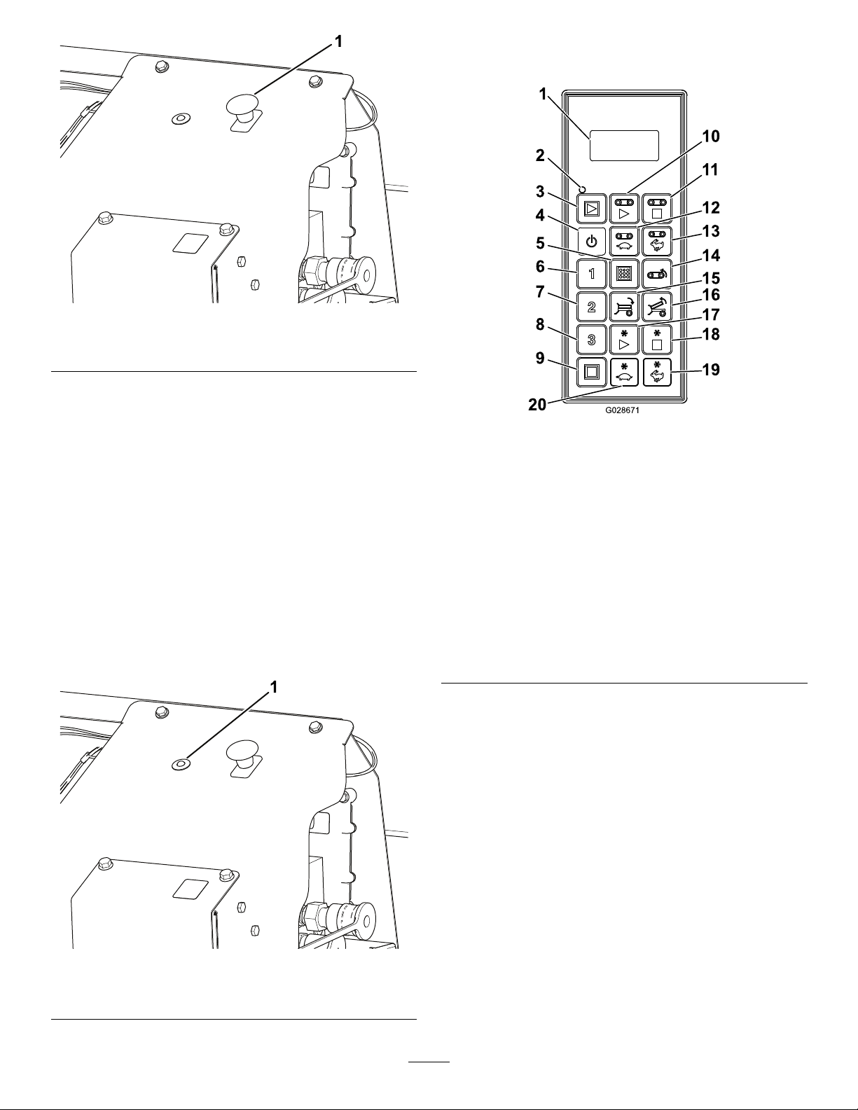
g234789
Figure17
1.E-STOPButton
DiagnosticLEDFunction
EHModels
AfteryoupulluptheE-STOPbutton,thediagnostic
LED(Figure18)illuminatesandremainsonfor5
seconds,turnofffor5seconds,andthenbegins
ashingat3Hz(3ashesasecond)untilyouturn
onthehandheldremote.Ifthelightturnsonfor5
secondsandthenstartsblinkingat10Hz(withor
withouta5secondpause),thereisafaultwiththe
machine;refertoCheckingFaultCodes(page54).
Note:Ifyouhadthehandheldremoteonwhenyou
pulleduptheE-STOPbutton,thelightwillnotash
at3Hz(3ashespersecond)afterturningofffor5
seconds.
g234788
Figure18
1.DiagnosticLED
HandheldRemote
EHModels
g028671
Figure19
1.LCDdisplay11.Floorstop
2.RemotestatusLED12.Decreaseoorspeed
3.Allstart:startsoorand
option
13.Increaseoorspeed
4.On/Off14.Floorreverse
5.Store:savespreset
settings
15.Tiltbeddown
6.Preset116.Tiltbedup
7.Preset217.Optionstart
8.Preset318.Optionstop
9.Allstop:stopsallfunctions19.Increaseoptionspeed
10.Floorstart20.Decreaseoptionspeed
19

Specications
Machine
Length4.8m(190inches)
Width1.98m(78inches)
Height2.2m(86inches)
Netweight(emptywithno
optionsinstalled)
1,360kg(3,000lb)
Hoppervolume3.06m3(4.0yd3)
Maximummaterialload5,353kg(11,800lb)
Maximumtowspeed
TractionUnitRequirements
Towingcapacity(maximumpayload)7,175kg(15,850
lb)
Minimumpower34kw(45
horsepower)
Rear-attachmenthydraulicsystemOpencenter
hydrauliccontrol
valve
minimum—without
optionsinstalled
32L/min(6US
gal/min)
Hydraulic-owrate
minimum—with
optionsinstalled
38L/min(10US
gal/min)
Hydraulicpressure(minimum)138bar(2,000psi)
Radio
Frequency2.4GHz
MaxOutputPower19.59dBm
Attachments/Accessories
AselectionofToroapprovedattachmentsand
accessoriesisavailableforusewiththemachine
toenhanceandexpanditscapabilities.Contact
yourAuthorizedServiceDealerorauthorizedToro
distributororgotowww.T oro.comforalistofall
approvedattachmentsandaccessories.
Toensureoptimumperformanceandcontinuedsafety
certicationofthemachine,useonlygenuineT oro
replacementpartsandaccessories.Replacement
partsandaccessoriesmadebyothermanufacturers
couldbedangerous,andsuchusecouldvoidthe
productwarranty.
Operation
BeforeOperation
BeforeOperationSafety
•Themachinehasdifferentbalance,weight,and
handlingcharacteristicscomparedtosomeother
typesoftowedequipment.Readandunderstand
thecontentsofthisOperator'sManualbefore
operatingthemachine.Becomefamiliarwithall
controlsandknowhowtostopquickly.
•Neverallowchildrentooperatethemachine.Do
notallowadultstooperatethemachinewithout
properinstructions.Onlytrainedandauthorized
personsshouldoperatethismachine.
•Keepallshieldsandsafetydevicesinplace.Ifa
shield,safetydeviceordecalisillegibleormissing,
repairorreplaceitbeforeoperatingthemachine.
•Themachineisdesignedonlyforoff-roaduse.
Themaximumrecommendedspeedis24km/h
(15mph)withoutaloadand13km/h(8mph)with
afullload.
•Tightenanyloosenuts,bolts,andscrewsto
ensurethatthemachineisinsafeoperating
condition.Ensurethatthemachinetongue
mountingpins,hitchpins,andtonguejackarein
placeandsecure.
•Donotmodifythisequipmentinanymanner.
•Thetongueistheareaonthemachinewherethe
hitchconnectstothetowvehicle.Theweightof
thetongueaffectsthestabilityofthemachine.
–Anegativeorpositivetongueweightcancause
injurywhenconnectingordisconnectingthe
machinetothetowvehicle.Wheninstalled,
ensurethatthejack-standsareproperly
engaged.
–Whentheweightofthetongueisforcedupinto
thehitchofthetowvehicle,thisproducesa
negativetongueweight.
Negativetongueweightmayalsoresultwhen
attachmentsaremountedontherearofthe
machine.
–Whentheweightofthetongueisforceddown
ontothehitchofthetowvehicle,thisproduces
apositivetongueweight.
•Neverattachthemachinetoorremovethe
machinefromthetractionunitifthereismaterialin
thehopper.Thetonguemayipup,causinginjury.
20
Other manuals for MH-400SH2
1
This manual suits for next models
3
Table of contents
Other Toro Industrial Equipment manuals

Toro
Toro Workman Topdresser 1800 User manual

Toro
Toro BRC-28 User manual

Toro
Toro OSMAC G3 Satellite User manual

Toro
Toro Greensmaster eFlex 1021 User manual

Toro
Toro 04246 User manual

Toro
Toro 60216C User manual

Toro
Toro Ultra Buggy e2500 User manual

Toro
Toro TX 1300 User manual

Toro
Toro Groundsmaster 3320 User manual

Toro
Toro Workman 07224-90001 Instruction Manual


