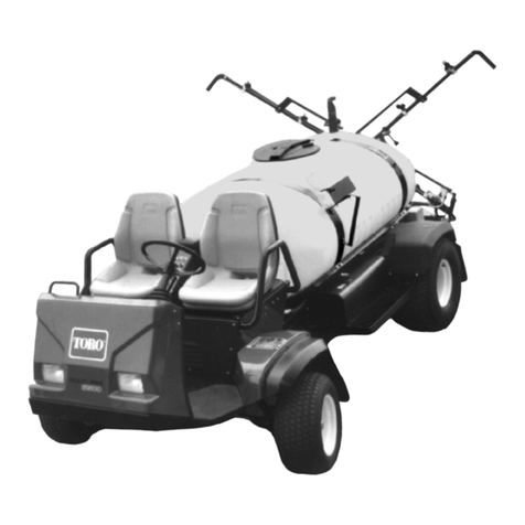
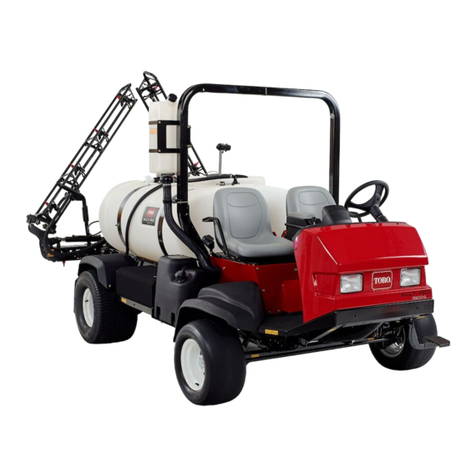
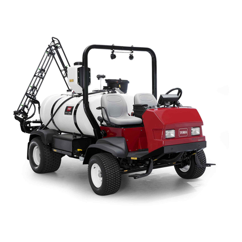
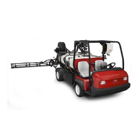
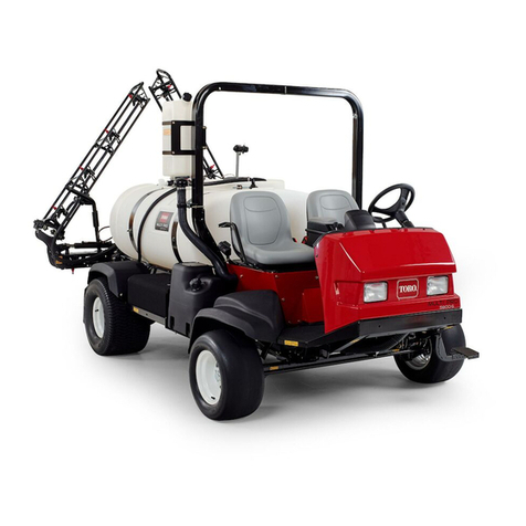
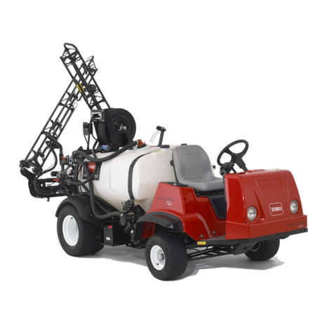
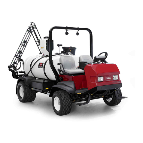
Toro Multi Pro 1750 User manual

FormNo.3406-976RevA
ValveConversionKit
MultiPro®1750TurfSprayer
ModelNo.136-0372
InstallationInstructions
Thevalveconversionkitisakitthatreplacesthesprayercontrolvalvesandrelatedcomponentsforaturfsprayapplication
vehicle.
YoumaycontactTorodirectlyatwww .Toro.comforproductsafetyandoperationtrainingmaterials,accessoryinformation,
helpndingadealer,ortoregisteryourproduct.
WARNING
CALIFORNIA
Proposition65Warning
ThisproductcontainsachemicalorchemicalsknowntotheStateofCaliforniato
causecancer,birthdefects,orreproductiveharm.
UseofthisproductmaycauseexposuretochemicalsknowntotheStateofCalifornia
tocausecancer,birthdefects,orotherreproductiveharm.
Safety
WARNING
Chemicalsubstancesusedinthespraysystemmaybehazardousandtoxictoyou,bystanders,animals,
plants,soils,orotherproperty.
•Carefullyreadandfollowthechemicalwarninglabelsandmaterialsafetydatasheets(MSDS)forall
chemicalsusedandprotectyourselfaccordingtothechemicalmanufacturer'srecommendations.For
example,useappropriatepersonalprotectiveequipment(PPE),includingfaceandeyeprotection,
gloves,orotherequipmenttoguardagainstpersonalcontactwithachemical.
•Theremaybemorethan1chemicalusedandinformationoneachchemicalshouldbeassessed.
•Refusetooperateorworkonthesprayerifthisinformationisnotavailable.
•Beforeworkingonaspraysystem,ensurethatthesystemhasbeentriplerinsedandneutralized
accordingtotherecommendationsofthechemicalmanufacturer(s)andthatallthevalveshavebeen
cycled3times.
•Verifythatthereisanadequatesupplyofcleanwaterandsoapnearby,andimmediatelywashoffany
chemicalsthatcontactyou.
©2016—TheToro®Company
8111LyndaleAvenueSouth
Bloomington,MN55420
Registeratwww.Toro.com.OriginalInstructions(EN)
PrintedintheUSA
AllRightsReserved*3406-976*A

SafetyandInstructionalDecals
Safetydecalsandinstructionsareeasilyvisibletotheoperatorandarelocatednearanyareaofpotential
danger.Replaceanydecalthatisdamagedormissing.
127-6976
1.Decrease2.Increase
127-6979
1.Pump-returnow3.Agitationow
2.Flow
127-6981
1.Bypass-returnow3.Boomspray
2.Flow
127-6982
1.Pump-returnow2.Boomspray
2

Installation
LooseParts
Usethechartbelowtoverifythatallpartshavebeenshipped.
ProcedureDescriptionQty.Use
1Nopartsrequired–Preparetoinstallthekit.
2Nopartsrequired–Disconnectingthepressure-sensetube.
3Nopartsrequired–Disconnectthewireharnessfromthe
valves.
4Nopartsrequired–Disconnecttheoptionalattachments.
5Nopartsrequired–Removetheboom-sectionvalves.
6Nopartsrequired–Removetheagitationnozzles.
7Nopartsrequired–Removetheagitation,rate,and
master-sprayvalves.
Cableties6
3-pinadapter5
84-pinadapter1
Replacethevalveelectricalconnectors.
Agitation,rate,andmaster-spray
manifold1
9Sectionvalvemanifold1
Installthevalveassemblies.
10Flow-meterhose—25x289mm(1x
11-3/8inches)1Installtheowmeterandhoses.
11Nopartsrequired–Connectthewireharness.
Handle1
Screw(6-32x5/8inch)1
Agitationthrottlevalve1
Bracket(nylon)1
Agitation-valvebracket1
Bolt(6x12mm)4
Eductor-shutoffvalve1
Eductor-shutoffbracket1
Flangelocknut(1/4inch)4
12
Flange-headbolt(5/16x3/4inch)2
Installingtheagitationthrottlevalveand
eductor–shutoffvalveformachineswith
theoptionaleductorkit.
13Agitation-nozzleassembly1Installingtheagitation-nozzleassembly
andhoses.
Returnhose—2.5x72cm(1x27-7/8
inches)1
Agitationsupplyhose—2.5x72cm(1x
28-1/4inches)1
14Bypasshose—2.5x110cm(1x43-1/2
inches)—machineswithouttheoptional
spraywandorelectrichosereelkit
1
Installthereturnhose,agitationsupply
hose,andbypasshose.
3

ProcedureDescriptionQty.Use
Sprayersupplyhose—2.5x73cm(1x
28-7/8inches)—machineswithoutthe
optionaleductorkit
1
Flangeclamp—40to64mm(1-9/16to
2-1/2inches)2
Gasket—25x35mm(1x1-3/8inches)2
Supportclamp—machineswithoutthe
optionaleductorkit1
Flange-headbolt(5/16x3/4
inch)—machineswithouttheoptional
eductorkit
1
Flangelocknut(5/16inch)—machines
withouttheoptionaleductorkit1
Lowersupplyhose—25x66cm(1
x25-3/4inches)machineswiththe
optionaleductorkit
1
Retainer(small)—machineswiththe
optionaleductorkit1
15
Uppersupplyhose—25x22cm(1x
8-5/8inches)machineswiththeoptional
eductorkit
1
Installthesprayersupplyhose.
Sectionbypasshose—2.5x146cm(1
x57-1/2inches)1
Supplyhose—left-boomsection—2x
205cm(3/4x80-13/16inches)1
Supplyhose—center-boomsection—2
x58cm(3/4x22-13/16inches)1
16
Supplyhose—right-boomsection—2x
170cm(3/4x66-13/16inches)1
Installthesprayvalvehoses.
Capandretrainer1
Straightbarbedtting(1/2inch)1
Quick-connecttting(socket)1
Hoseclamp13to32mm(1/2to1-1/4
inches)2
Hose—1.3x762cm(1/2x300inches)1
Hose—1.3x180cm(1/2x83inches)1
2412-36Hoseclamp6to11mm(1/4
to7/16inch)2
Bypassshutoffvalve1
17
Sectionbypasshose—2.5x146cm(1
x57-1/2inches)1
Installtheshutoffvalveandhosefor
theoptionalspraygunkitorelectric
hose-reelkit.
Eductorsupplyhose2x88cm(3/4x
34-11/16inches)1
18Retainer(small)1
Installthehosefortheoptionaleductor
kit.
19Nopartsrequired–Connectthepressuresensetube.
20Nopartsrequired–CompletetheinstallationoftheGeoLink
spraysystem-nishingkit.
4

1
PreparingtoInstalltheKit
NoPartsRequired
PreparingtheSprayerTankand
OptionalRinseTank
1.Parkthemachineonalevelsurface.
2.Engagetheparkingbrake.
3.Shutofftheengineandremovethekey.
Figure1
PreparingtheSprayerandOptional
RiseTankKit
1.Cleanthesprayer;refertoCleaningtheSprayerinthe
Operator’sManualforthemachine.
Important:Youmustcompletelyemptythe
sprayertankbeforeinstallingtheValveConversion
Kit.
2.Formachineswiththeoptionaltank-rinsekit,
performthefollowing:Pumpthewaterfromthe
rinsetankintothesprayertank;refertoOperating
theRinseKitintheInstallationInstructionsforthe
Tank-RinseKit.
3.Drainthewaterfromthesprayertank(Figure2);refer
toCleaningtheSprayerintheOperator’sManualforthe
machine.
Figure2
1.Valvebracket3.Drainvalve
2.Mountbolt
5

DisconnectingtheBattery
WARNING
Electricalsparkscancausethebatterygassesto
explode,resultinginpersonalinjury.
Incorrectbatterycableroutingcoulddamagethe
sprayerandcables,causingsparks.
•Alwaysdisconnectthenegative(black)battery
cablebeforedisconnectingthepositive(red)
cable.
•Alwaysconnectthepositive(red)batterycable
beforeconnectingthenegative(black)cable.
Batteryterminalsormetaltoolscouldshortagainst
metalsprayercomponents,causingsparks.
•Whenremovingorinstallingthebattery,donot
allowthebatteryterminalstotouchanymetal
partsofthesprayer.
•Donotallowmetaltoolstoshortbetweenthe
batteryterminalsandmetalpartsofthesprayer.
•Alwayskeepthebatterystrapinplacetoprotect
andsecurethebattery.
1.Movethemachineontoalevelsurface,engagethe
parkingbrake,shutoffthepump,andextendtheleft
andrightboomsectionstothehorizontalposition.
2.RotatethekeyswitchtotheOFFposition,andremove
thekey;refertotheOperator’sManual.
3.Unlatchtheseatbypushingtheseat-latchhandle
rearward(Figure3).
Figure3
1.Seat3.Seat-latchhandle
2.Proprod
4.Rotatetheseatandseatplateforwarduntiltheendof
theproprodattheprop-rodbracketisatthebottom
ofthegrooveofthebracket(Figure3).
5.Allowtheenginetocoolcompletely.
6.Disconnectthenegative(black—ground)cablefrom
thebatterypost(Figure4).
Note:Ensurethattheterminalofthebatterycable
doesnottouchthepost.
Figure4
1.Positivebatterypost4.Nut
2.Insulatorcover—positive
(red)cable
5.Bolt
3.Negativebatteryterminal6.Negativecable
7.Slipbacktheinsulatorcoverthedisconnectthepositive
(red)cablefromthebatterypost(Figure4).
6

2
Disconnectingthe
Pressure-SenseTube
NoPartsRequired
Procedure
1.Pressinthecollarforthetubecouplerintheendcap
oftherightboom-sectionvalve(Figure5).
Figure5
1.Ported-captting(endof
therightboom-section
valve)
3.Pressure-sensetube
2.Tubecoupler
2.Pullthepressure-sensetubeforthedashgaugeoutof
thetubecoupler(Figure5).
3
DisconnectingtheWire
HarnessfromtheValves
NoPartsRequired
Procedure
1.Removethescrewthatsecuresthe3-contactconnector
ofthewireharnesslabeledRIGHTSPRAYVALVEfrom
rightsprayvalve(Figure6).
Figure6
1.Rightsprayvalve4.Spray-valveconnector
2.Centersprayvalve5.3-contactconnector
3.Leftsprayvalve6.Screw
2.Removethe3-contactconnectorofthewireharness
fromthesprayvalve(Figure6).
3.Repeatsteps1and2forthe3-contactconnectorsof
thewireharnesslabeledCENTERSPRAYV ALVEand
LEFTSPRAYVALVE.
4.Removethescrewthatsecuresthe3-contactconnector
ofthewireharnesslabeledMASTERSPRAYVALVEfrom
rightmastersprayvalve(Figure7).
7

Figure7
1.Mastersprayvalve4.Valveelectricalconnector
(agitationvalve)
2.Ratevalve5.3-contactconnector
(wireharness—AGITATION
VALVE)
3.Agitationvalve6.Valveelectricalconnector
(mastersprayvalve)
5.Removethe3-contactconnectorofthewireharness
fromthevalve(Figure7).
6.Repeatsteps4and5forthe3-contactconnectorsof
thewireharnesslabeledRATEV ALVEandAGITATION
VALVE.
7.Removethe5push-infastenersofthewire
harnessfromthesection-valvebracketandthe
agitation/rate/master-spraybracket.
Figure8
1.Bracket(throttlevalve)3.Bracket
(agitation/rate/master-spray
valve)
2.Push-infastener
8

4
DisconnectingtheOptional
Attachments
NoPartsRequired
DisconnectingtheOptionalEductorKit
1.Removetheangeclampthatsecurestheanged
hose-barbofthesupplyhosetotheinletangeofthe
eductor(Figure9).
Figure9
1.Inletange(eductor)3.Flangeclamp
2.Gasket4.Flanged-hose-barb
(supplyhose)
2.Removetheangedhosebarbandgasketfromthe
eductor(Figure9).
Note:Retaintheangeclampandgasketfor
installationin18InstallingtheSupplyHoseforthe
OptionalEductorKit(page47).Younolongerneed
thesupplyhoseandyouwillremoveitwiththe
agitation,rate,andmastersprayvalvesin7Removing
theAgitation,Rate,andMaster-SprayValves(page14).
3.Removetheretainerthatsecuresthe90°barbedtting
ofthesprayersupplyhosetotheT-ttinglocated
forwardofthepressure-reliefvalve(Figure11).
Note:RetaintheretainersforinstallationinInstalling
theSprayerSupplyHose—Machinewithoutthe
OptionalEductorKit(page34).
Figure10
Figure11
1.Retainer5.Sprayersupplyhose
2.90°barbedtting(sprayer
supplyhose)
6.Pressure-reliefvalve
3.Frontofthemachine7.3-wayvalve
4.T-tting
4.Removethe90°barbedttingfromtheT-tting
(Figure11).
9

DisconnectingtheOptionalElectric
Hose-ReelKit
1.Removethehoseclampthatsecuresthesupplyhoseto
thebarbedttingattheinletswivelofthereel(Figure
12).
Figure12
1.Barbedtting(inletswivel)3.Supplyhose(hosereel)
2.Hoseclamp
2.Removethesupplyhosefromthebarbedtting(Figure
12).
3.Removetheinlethosefromthesupportclampatthe
forwardstrapofthesprayertank.
Note:Younolongerneedthesupplyhoseand
youwillremoveitwiththeboomsectionvalvesin5
RemovingtheBoom-SectionValves(page11).
DisconnectingtheOptionalHand
Spray-WandKit
1.Removethehoseclampthatsecuresthesupplyhoseto
thebarbedttingofthespraygun(Figure13).
Figure13
1.Supplyhose(handspray
wand)
3.Barbedtting(spraygun)
2.Hoseclamp
2.Removethesupplyhosefromthebarbedtting(Figure
13)
Note:Younolongerneedthesupplyhoseand
youwillremoveitwiththeboomsectionvalvesin5
RemovingtheBoom-SectionValves(page11).
10

5
RemovingtheBoom-Section
Valves
NoPartsRequired
RemovingtheBoom-SectionHoses
1.Attheouter-boomsection,removethehoseclamp
thatsecuresthesupplyhosefortheboomsectionto
thebarbedT-tting(Figure14).
Note:Retainthehoseclampforinstallationin
InstallingtheSupplyHosestotheBoomSections
(page39)
Figure14
1.Outerboomsection4.Hoseclamp
2.Supplyhose(outer-boom
section)
5.R-clamp
3.BarbedT-tting
2.RemovethehosefromtheT-tting(Figure14).
3.RemovethefreeendofthehosefromtheR-clamp
(Figure14).
4.Repeatsteps1through3forthesupplyhoseatthe
otherouter-boomsection.
5.Underthecenter-boomsection,removethehose
clampthatsecuresthesupplyhosefortheboom
sectiontothebarbedT-tting(Figure15).
Note:Retainthehoseclampforinstallationin
InstallingtheSupplyHosestotheBoomSections
(page39).
Figure15
1.Centerboom-sectionvalve4.Supplyhose(center-boom
section)
2.Center-boomsection5.Hoseclamp
3.Leftsideofthemachine6.BarbedT-tting
11

RemovingtheFlowMeterfromthe
ValveManifolds
1.Removetheangeclampthatsecuresthebarbed
angettingoftheowmeterhosetotheowmeter
(Figure16).
Figure16
1.Flangeclamp4.Barbedangetting
(ow-meterhose)
2.Gasket5.Adaptertting(left
boom-sectionvalve)
3.Flowmeter
2.Removetheangeclampthatsecuretheowmeter
totheadapterttingattheleftboom-sectionvalve
(Figure16).
3.Removetheowmeterand2gasketsfromthevalve
manifolds(Figure16).
Note:Settheowmeteraside—donotremovethe
electricalconnector;retaintheangeclampsand
gasketsforinstallationinInstallingtheFlowMeter
(page26).
RemovingtheBypassHosefromthe
Boom-SectionValves
1.Removetheretainerthatsecuresthe90°barbedtting
ofthebypasshosefromthesocketttingofthebypass
valveattherightboomsectionvalve(Figure17).
Figure17
1.Bypassmanifold
(boom-sectionvalves)
3.Bypasshose
2.Retainer
2.Removethebypasshosefromthebypassvalve(Figure
17).
12

RemovingtheBoom-SectionValves,
SupplyHoses,andSection-Valve
Mount
1.Removethe4ange-headbolts(5/16x3/4inch)that
securethesection-valvebrackettothesection-valve
mount(Figure18).
Note:Retaintheange-headboltsforinstallationin
InstallingtheSectionValveManifold(page24).
Figure18
1.Bracket(section-valve)2.Flange-headbolt(5/16x
3/4inch)
2.Lifttheboom-sectionvalves,supplyhoses,and
section-valvebracketfromthemachine(Figure19).
Note:Younolongerneedthevalves,hoses,and
bracket.
Figure19
6
RemovingtheAgitation
Nozzles
NoPartsRequired
RemovingtheAgitationNozzlesfrom
theSprayerTank
1.Removethe3retainersthatsecuretheagitationnozzles
tothebulkheadttingsattheleftsideofthesprayer
tank(Figure20).
Note:Retaintheretainersforinstallationin13
InstallingtheAgitation-NozzleAssemblyandHoses
(page30).
Figure20
1.Bulkheadtting3.Retainer
2.Agitationnozzle
2.Removetheagitationnozzlesfromthebulkhead
ttings(Figure20).
13

RemovingtheBracketfortheAgitation
ThrottleMount
1.Removethe2ange-headbolts(5/16x5/8inch)that
securetheagitationthrottlevalvetothethrottle-valve
bracket(Figure21).
Figure21
1.Agitationsupplyhose3.Bracket(throttlevalve)
2.Flange-headbolt(5/16x
5/8inch)
4.Agitationthrottlevalve
2.Removethe2ange-headbolts(5/16x3/4inch)that
securethethrottle-valvebrackettothethrottle-valve
mount,andremovethebracket(Figure22).
Note:Younolongerneedthe4ange-headboltsand
throttle-valvebracket.
Figure22
1.Mount(throttle-valve
bracket)
3.Flange-headbolt(5/16x
3/4inch)
2.Bracket(throttlevalve)
7
RemovingtheAgitation,Rate,
andMaster-SprayValves
NoPartsRequired
DisconnectingtheReturn,
Sprayer-Supply,andBypassHoses
1.Atthebackofthemachine,removetheretainerthat
securesthe90°barbedttingofthereturnhosetothe
T-ttinglocatedinboardofthepressure-reliefvalve
(Figure23).
Note:RetaintheretainersforinstallationinInstalling
theReturnHose(page31).
Figure23
1.Pressure-reliefvalve4.T-tting
2.90°barbedtting(return
hose)
5.Retainer
3.Frontofthemachine
2.Removethe90°barbedttingfromtheT-tting
(Figure23).
3.Removetheretainerthatsecuresthe90°barbedtting
ofthesprayersupplyhosetotheT-ttinglocated
forwardofthepressure-reliefvalve(Figure24).
Note:RetaintheretainersforinstallationinInstalling
theSprayerSupplyHose—Machinewithoutthe
OptionalEductorKit(page34).
14

Figure24
1.Retainer4.T-tting
2.90°barbedtting(sprayer
supplyhose)
5.Pressure-reliefvalve
3.Frontofthemachine
4.Removethe90°barbedttingfromtheT-tting
(Figure24).
5.Atthetopoftheofthesprayertank,removethe
retainerthatsecuresthestraightbarbedttingofthe
bypasshosetotheT-tting(Figure25).
Note:RetaintheretainersforinstallationinInstalling
theBypassHose—MachineswithouttheOptional
SprayWandKitorElectricHoseReelKit(page33).
Figure25
1.Retainer3.Straightbarbedtting
(bypasshose)
2.T-tting
6.RemovethestraightbarbedttingfromtheT-tting
(Figure25).
RemovingtheAgitation,Rate,and
Master-SprayValvesfromtheMachine
1.Whilesupportingthebracketfortheagitation,rate,
andmaster-sprayvalves,removethe3ange-head
bolts(5/16x3/4inch)thatsecurevalvebrackettothe
mount(Figure26).
Figure26
1.Mount3.Flange-headbolts(5/16x
3/4inch)
2.Bracket
2.Removethebracket,valves,hoses,andagitation
nozzlesfromthemachine(Figure27).
Note:Retainthe3ange-headbolts(5/16x3/4inch)
forinstallationinInstallingtheAgitation,Rate,and
Master-SprayValveManifold(page24);younolonger
needthebracket,valves,hoses,andagitationnozzles.
Figure27
15

RemovingtheSectionBypassHose
1.Removetheretainerthatsecuresthe90°barbedtting
ofthesectionbypasshosefortheboom-sectionvalves
fromthebulkheadttingatthebackofthesprayer
tank(Figure28).
Figure28
1.Retainer3.Bulkheadtting(sprayer
tank)
2.90°barbedtting—section
bypasshose
(boom-sectionvalves)
2.Removethe90°barbedttingfromthebulkhead
tting(Figure28).
Note:RetaintheretainersforinstallationinInstalling
theSectionBypassHose(page37);younolongerneed
thebypasshosefortheboom-sectionvalves.
8
ReplacingtheValveElectrical
Connectors
Partsneededforthisprocedure:
6Cableties
53-pinadapter
14-pinadapter
PreparingtheWireHarness
1.Atthebackofthemachine,removethe3tiewrapsthat
securetheconvolutedtubingandinline-fuseblockto
thewireharnessforthebranchlabeledRIGHTSPRAY
VALVEasshowninFigure29.
Figure29
1.DINconnectors4.Inline-fuseblock
2.Label5.Cableties
3.Convolutedtubing
2.Remove76mm(3inches)sectionofconvolutedtubing
asshowninFigure30.
Figure30
1.Removedsectionofconvolutedtube—76mm(3inches)
3.Positiontheconvolutedtubingtowardthemainbranch
ofthewireharnessasshowninFigure31.
16

Figure31
1.Inline-fuseblock3.Cabletie
2.Positionedconvoluted
tubing
4.Aligntheinline-fuseblocktotheconvolutedtubingas
showninFigure31andsecurethefuseblocktothe
tubingwithacabletie.
5.CuttheDINconnectorharnessbelowtheDIN
connector(Figure32)
Note:Cuttheharnessasclosetotheconnector.
Figure32
1.DINconnector
6.Removea70mm(2-3/4inches)sectionofthe
sheathingfromtheDINconnectorharness(Figure33).
Figure33
1.Cablesheathing70mm
(2-3/4inches)
3.Removedsectionofwire
insulation—8mm(5/16
inch)
2.Wiresplice(factorymade)
7.Remove8mm(5/16inch)ofinsulationfromthe3
wiresoftheDINconnectorharness(Figure33).
8.Repeatsteps1though7forthewireharnessbranches
labelsCENTERSPRAYVALVE,LEFTSPRAYVALVE,RATE
VALVE,AGITATIONVALVE,andMASTERSPRAYVALVE.
InstallingtheRightSpray-Valve
Connector
1.AlignthewireinsulationcolorsoftheDINharness
tothewireinsulationcolorsofthe3-pinadapterfor
therightsprayvalveasshowninthewiretableforthe
rightsprayvalve.
17

WiringTable—RightSprayValve
Wirecolorcodes—DINwire
harness
Wirecolorcodes—3-pin
adapter
BrownPink
BlueBlack
Yellow/greenWhite
2.InsertthewireoftheDINwireharnessintothe
butt-spliceconnectorofthe3-pinadapter(Figure34).
Figure34
1.3-pinadapter3.Butt-spliceconnector
2.DINwireharness4.Exposedwire9.5mm(3/8
inch)
3.Centerthecrimpingtooloverthebutt-spliceconnector
andwiresandcrimptheconnectorsecurely(Figure35).
Figure35
1.3-pinadapter3.Connector(centerspray)
2.Wireharnessbranch(left
spray)
4.Connector(rightspray)
4.Repeatsteps2and3forthe2remainingwires.
5.Useaheatguntoshrinktheinsulatingsleevesofthe3
butt-spliceconnectors(Figure36).
Figure36
18

InstallingtheCenterSpray-Valve
Connector
1.AlignthewireinsulationcolorsoftheDINharnessto
thewireinsulationcolorsofthe3-pinadapterforthe
centersprayvalveasshowninthewiretableforthe
centersprayvalve.
WiringTable—CenterSprayValve
Wirecolorcodes—DINwire
harness
Wirecolorcodes—3-pin
adapter
BrownPink
BlueBlack
Yellow/greenWhite
2.InsertthewireoftheDINwireharnessintothe
butt-spliceconnectorofthe3-pinadapter
3.Centerthecrimpingtooloverthebutt-spliceconnector
andwiresandcrimptheconnectorsecurely.
4.Repeatsteps2and3forthe2remainingwires.
5.Useaheatguntoshrinktheinsulatingsleevesofthe
3butt-spliceconnectors.
InstallingtheLeftSpray-Valve
Connector
1.AlignthewireinsulationcolorsoftheDINharnessto
thewireinsulationcolorsofthe3-pinadapterforthe
leftsprayvalveasshowninthewiretablefortheleft
sprayvalve.
WiringTable—LeftSprayValve
Wirecolorcodes—DINwire
harness
Wirecolorcodes—3-pin
adapter
BrownPink
BlueBlack
Yellow/greenWhite
2.InsertthewireoftheDINwireharnessintothe
butt-spliceconnectorofthe3-pinadapter
3.Centerthecrimpingtooloverthebutt-spliceconnector
andwiresandcrimptheconnectorsecurely.
4.Repeatsteps2and3forthe2remainingwires.
5.Useaheatguntoshrinktheinsulatingsleevesofthe
3butt-spliceconnectors.
InstallingtheRate-ValveConnector
1.Cutoffthebutt-spliceconnectorsforthepinkwire
andblackwiresofthe4-pinadapter(Figure37).
Figure37
1.4-pinadapter3.Pinkwire
2.Blackwire4.Butt-spliceconnector
2.Strip8mm(5/16inch)ofinsulationfromthepinkand
blackwiresofthe4-pinadapter(Figure38).
Note:Youwillconnectthepinkandblackwiresof
the4-pinadapterinInstallingtheMaster-SprayValve
Connector(page22).
Figure38
1.Blackwire(4-pinadapter)3.Removedsectionofwire
insulation—8mm(5/16
inch)
2.Pinkwire(4-pinadapter)
3.AlignthebrownwireoftheDINharnesswiththegray
wireofthe4-pinadapterfortheratevalve(Figure39);
refertothewiretablefortheratevalve.
19

Figure39
1.4-pinadapter(ratevalve)4.Bluewire(DINwire
harness)
2.Graywire(4-pinadapter)5.Brownwire(DINwire
harness)
3.Greenwire(4-pinadapter)6.DINharness(ratevalve)
WiringTable—RateValve
Wirecolorcodes—DINwire
harness
Wirecolorcodes—4-pin
adapter(rate-valveposition)
NotapplicablePink
NotapplicableBlack
BrownGray
BlueGreen
4.InsertthebrownwireoftheDINwireharnessinto
thebutt-spliceconnectoronthegraywireofthe4-pin
adapterfortheratevalve.
5.Centerthecrimpingtooloverthebutt-spliceconnector
andwiresandcrimptheconnectorsecurely.
6.InsertthebluewireoftheDINharnessandbutt-splice
connectoronthegreenwireofthe4-pinadapterfor
theratevalve(Figure39).
7.Centerthecrimpingtooloverthebutt-spliceconnector
andwiresandcrimptheconnectorsecurely.
8.Useaheatguntoshrinktheinsulatingsleevesofthe
butt-spliceconnectorsofthewiresthatyouinstalled
insteps3through6.
9.TerminatethegreenandyellowwireoftheDIN
connectorasfollows:
A.Cuttheconductorsofthegreenandyellowwire
ushwiththeinsulation(Figure40).
Figure40
1.Greenandyellowwire
(cuttingtheconductor)
3.Tapingwirestogether
2.Tapingtheendofthe
greenandyellowwire
B.Wraptheendofthegreenandyellowwirewith
electricaltapetosealthewire(Figure40).
C.Foldthegreenandyellowwiretothebrownwire
andbluewireandwrapthe3wirestogetherwith
theelectricaltape(Figure40).
20
Other manuals for Multi Pro 1750
3
This manual suits for next models
1
Table of contents
Other Toro Paint Sprayer manuals

Toro
Toro Ultra Sonic Boom 133-2808 User manual

Toro
Toro Multi Pro 41240 User manual

Toro
Toro GeoLink 41624 User manual

Toro
Toro 41582 User manual

Toro
Toro Multi Pro 5800 User manual

Toro
Toro GeoLink CL-55 User manual

Toro
Toro 125-8120 User manual

Toro
Toro Multi Pro 5800-D User manual

Toro
Toro Multi-Pro 5800 User manual

Toro
Toro Ultra Sonic Boom 41218 User manual