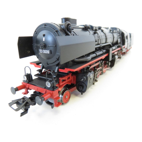
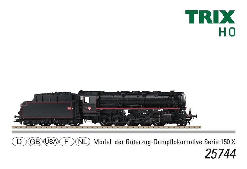
Trix 22251 User manual

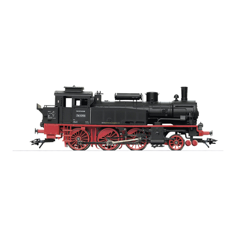
Modell der Dampflokomotive Reihe BVI
22251
F
D
GB
USA
NL

2

3
Inhaltsverzeichnis: Seite
Informationen zum Vorbild 4
Sicherheitshinweise 6
Wichtige Hinweise 6
Multiprotokollbetrieb 6
Hinweise zum Digitalbetrieb 7
Schaltbare Funktionen 9
Parameter/Register 10
Betriebshinweise 26
Wartung und Instandhaltung 27
Ersatzteile 34
Table of Contents: Page
Information about the prototype 4
Safety Notes 11
Important Notes 11
Multi-Protocol Operation 11
Notes on digital operation 12
Controllable Functions 14
Parameter/Register 15
Information about operation 26
Service and maintenance 27
Spare Parts 34
Sommaire : Page
Informations concernant la locomotive réelle 5
Remarques importantes sur la sécurité 16
Information importante 16
Mode multiprotocole 16
Remarques relatives au fonctionnement
en mode digital 17
Fonctions commutables 19
Paramètre/Registre 20
Remarques sur l’exploitation 26
Entretien et maintien 27
Pièces de rechange 34
Inhoudsopgave: Pagina
Informatie van het voorbeeld 5
Veiligheidsvoorschriften 21
Belangrijke aanwijzing 21
Multiprotocolbedrijf 21
Aanwijzingen voor digitale besturing 22
Schakelbare functies 24
Parameter/Register 25
Opmerkingen over de werking 26
Onderhoud en handhaving 27
Onderdelen 34

4
Information zum Vorbild
Die Lokomotiven der Gattung B VI bildeten über einen
langen Zeitraum das Rückgrat für die Beförderung von
Schnellzügen und Postzügen bei den Königlich Bayerischen
Staatseisenbahnen.
Während ihrer Bauzeit 1863 –1871 wurden die Maschinen
immer wieder verbessert und die Lokomotiven aus den er-
sten Bauserien umgebaut. So wurde u. a. durch den Einbau
neuer Kessel der Dampfdruck von 8 bar auf 10 bar erhöht
und der Wetterschirm zum besseren Schutz von Lokomo-
tivführer und Heizer gegen Fahrtwind und Regen durch ein
geschlossenes Führerhaus ersetzt.
Da Bayern kaum über eigene Kohlevorräte verfügte,
waren viele bayerische Lokomotiven für die Feuerung mit
heimischem Torf eingerichtet. Der Heizwert des Torfs war
im Vergleich zur Steinkohle relativ gering. Die Torftender
hatten deshalb ein größeres Fassungsvolumen und waren
wegen des nässeempfindlichen Brennstoffs mit einem Dach
versehen.
Ein weiteres äußeres Merkmal der torfbefeuerten Lokomo-
tiven waren birnen- oder kegelförmige Schornsteine, die
übermäßigen Funkenflug verhindern sollten.
Information about the Prototype
Over a long period of time the class B VI locomotives were
the backbone of the motive power for express trains and
mail trains on the Royal Bavarian State Railways.
During the period of their construction,1863–1871, these
units were constantly improved, and the locomotives from
the first series were rebuilt. Hence, for example, the instal-
lation of new boilers increased the steam pressure from 116
to 145 pounds per square inch, and the open driving platform
with just a canopy roof was replaced by an enclosed cab for
improved protection of the engineer and fireman.
Since Bavaria had hardly any of its own coal deposits, many
Bavarian locomotives were equipped for burning the native
peat. The effectiveness of peat as a fuel was relatively low
in comparison with coal. The peat tender was therefore
larger in volume and was provided with a roof to protect the
moisture-sensitive fuel. Another external feature of peat-
fired locomotives were the pear or balloon-shaped smoke
stacks, which were supposed to prevent sparks from flying.

5
Informations concernant la locomotive réelle
Les locomotives de la série B VI constituèrent pendant
longtemps l’épine dorsale de l’acheminement des trains
rapides et des trains postaux des Chemins de fer Royaux
Bavarois (K.Bay.Sts.B.).
Tout au long de la période de leur construction (1863 –1871),
les machines furent sans cesse améliorées et les locomo-
tives issues des premières séries de construction furent
transformées. Ainsi, la pression de la vapeur a notamment
été augmentée de 8 à 10 bars grâce à l’intégration de
nouvelles chaudières et l’écran de protection contre les
intempéries a été remplacé par un poste de conduite fermé,
afin d’assurer une meilleure protection du mécanicien et du
chauffeur contre le vent et la pluie.
Etant donné que la Bavière ne disposait pratiquement
pas de réserves de charbon sur son propre territoire, de
nombreuses locomotives bavaroises étaient équipées pour
une chauffe à la tourbe recueillie dans le pays. Le pouvoir
calorifique de la tourbe étant relativement faible par rapport
à celui de la houille. Les tenders étaient, par conséquent,
nettement plus grands et couverts en raison de la sensibilité
du combustible à l’humidité. Les cheminées en forme de
poire ou d’entonnoir constituent une autre caractéristique
apparente des locomotives à tourbe. Elles étaient destinées
à empêcher les projections trop importantes d’escarbilles.
Informatie van het voorbeeld
De lokomotieven van de serie B VI vormden gedurende
lange tijd de ruggegraat van het vervoer van sneltreinen en
posttreinen bij de Königlich Bayerische Staatseisenbahnen.
Tijdens hun constructietijd van 1863 tot 1871 werden de
machines voortdurend verbeterd en de lokomotieven uit
de eerste series omgebouwd. Zo werd bij de inbouw van
nieuwe ketels de stoomdruk van 8 bar tot 10 bar verhoogd
en werd het scherm dat de machinist en de stoker tegen
rijwind en regen beschermde, door een gesloten cabine
vervangen.
Omdat Beieren nauwelijks over eigen kolenvoorraden
beschikte, waren veel Beierse lokomotieven voor het stoken
van inheemse turf ingericht. De stookwaarde van turf was
in vergelijking met steenkool gering. De turftenders hadden
daarom een groter volume en waren om de vochtgevoelige
turf tegen vocht te vrijwaren van een dak voorzien. Een
ander uiterlijk kenmerk van de met turf gestookte lokomotie-
ven waren de peer- of kegelvormige schoorstenen, die een
overmatige vonkenregen moesten voorkomen.

6
Sicherheitshinweise
• DieLokdarfnurmiteinemdafürbestimmtenBetriebssystem
eingesetzt werden.
• Analogmax.15Volt=,digitalmax.22Volt~.
• DieLokdarfnurausalseinerLeistungsquelleversorgt
werden.
• BeachtenSieunbedingtdieSicherheitshinweiseinder
Bedienungsanleitung zu Ihrem Betriebssystem.
• FürdenkonventionellenBetriebderLokmussdasAnschluss-
gleis entstört werden. Dazu ist das Entstörset
611 655 zu verwenden. Für Digitalbetrieb ist das Entstörset
nicht geeignet.
• ACHTUNG! Funktionsbedingte scharfe Kanten und Spitzen.
• SetzenSiedasModellkeinerdirektenSonneneinstrahlung,
starken Temperaturschwankungen oder hoher Luftfeuchtig-
keit aus.
Wichtige Hinweise
• DieBedienungsanleitungunddieVerpackungsindBestand-
teile des Produktes und müssen deshalb aufbewahrt sowie
bei Weitergabe des Produktes mitgegeben werden.
• FürReparaturenoderErsatzteilewendenSiesichbittean
Ihren Trix-Fachhändler.
• GewährleistungundGarantiegemäßderbeiliegendenGaran-
tieurkunde.
• Entsorgung:www.maerklin.com/en/imprint.html
• DervolleFunktionsumfangistnurunterTrixSystems,DCC
und unter mfx verfügbar.
• Eingebaute,fahrtrichtungsabhängigeStirnbeleuchtung.
Im Digitalbetrieb schaltbar.
• BefahrbarerMindestradius360mm.
Multiprotokollbetrieb
Analogbetrieb
Der Decoder kann auch auf analogen Anlagen oder Gleis-
abschnitten betrieben werden. Der Decoder erkennt die
analoge Gleichspannung (DC) automatisch und passt sich
der analogen Gleisspannung an. Es sind alle Funktionen,
die unter mfx oder DCC für den Analogbetrieb eingestellt
wurden aktiv (siehe Digitalbetrieb).
Digitalbetrieb
Der Decoder ist ein Multiprotokolldecoder. Der Decoder
kannunterfolgendenDigital-Protokolleneingesetztwerden:
mfx oder DCC.
Das Digital-Protokoll mit den meisten Möglichkeiten ist das
höchstwertige Digital-Protokoll. Die Reihenfolge der Digital-
ProtokolleistinderWertungfallend:
Priorität1:mfx
Priorität2:DCC
Priorität3:DC
Hinweis: Digital-Protokolle können sich gegenseitig beein-
flussen. Für einen störungsfreien Betrieb empfehlen wir,
nicht benötigte Digital-Protokolle mit CV 50 zu deaktivieren.
Deaktivieren Sie, sofern dies Ihre Zentrale unterstützt, auch
dort die nicht benötigten Digital-Protokolle.
Werden zwei oder mehrere Digital-Protokolle am Gleis
erkannt, übernimmt der Decoder automatisch das höchst-
wertige Digital-Protokoll, z.B. mfx/DCC, somit wird das
mfx-Digital-Protokoll vom Decoder übernommen.
Hinweis: Beachten Sie, dass nicht alle Funktionen in allen
Digital-Protokollen möglich sind. Unter mfx und DCC können

7
einige Einstellungen von Funktionen, welche im Analog-
Betrieb wirksam sein sollen, vorgenommen werden.
Hinweise zum Digitalbetrieb
• DiegenaueVorgehensweisezumEinstellenderdiversen
Parameter entnehmen Sie bitte der Bedienungsanleitung
Ihrer Mehrzug-Zentrale.
• DieabWerkeingestelltenWertesindfürmfxgewählt,so
dass ein bestmöglichstes Fahrverhalten gewährleistet ist.
Für andere Betriebssysteme müssen gegebenenfalls Anpas-
sungen getätigt werden.
• DerBetriebmitgegenpoligerGleichspannungimBremsab-
schnitt ist mit der werkseitigen Einstellung nicht möglich. Ist
diese Eigenschaft gewünscht, so muss auf den konventio-
nellenGleichstrombetriebverzichtetwerden(CV29/Bit2=0).
mfx-Protokoll
Adressierung
• KeineAdresseerforderlich,jederDecodererhälteineeinma-
lige und eindeutige Kennung (UID).
• DerDecodermeldetsichaneinerCentralStationoderMobile
Station mit seiner UID automatisch an.
Programmierung
• DieEigenschaftenkönnenüberdiegrascheOberächeder
Central Station bzw. teilweise auch mit der Mobile Station
programmiert werden.
• EskönnenalleCongurationVariablen(CV)mehrfachgele-
sen und programmiert werden.
• DieProgrammierungkannentwederaufdemHaupt-oder
dem Programmiergleis erfolgen.
• DieDefaulteinstellungen(Werkseinstellungen)können
wieder hergestellt werden.
• Funktionsmapping:FunktionenkönnenmitHilfederCentral
Station 60212 (eingeschränkt) und mit der Central Station
60213/60214/60215 beliebigen Funktionstasten zugeordnet
werden (siehe Hilfe in der Central Station).
DCC-Protokoll
Adressierung
• KurzeAdresse–LangeAdresse–Traktionsadresse
• Adressbereich:
1 – 127 kurze Adresse, Traktionsadresse
1 – 10239 lange Adresse
• JedeAdresseistmanuellprogrammierbar.
• KurzeoderlangeAdressewirdüberdieCVsausgewählt.
• EineangewandteTraktionsadressedeaktiviertdieStandard-
Adresse.
Programmierung
• DieEigenschaftenkönnenüberdieCongurationsVariablen
(CV) mehrfach geändert werden.
• DieCV-NummerunddieCV-Wertewerdendirekteingegeben.
• DieCVskönnenmehrfachgelesenundprogrammiertwerden
(Programmierung auf dem Programmiergleis).
• DieCVskönnenbeliebigprogrammiertwerden(Programmie-
rung auf dem Hauptgleis PoM). PoM ist nur bei den in der CV-
Tabelle gekennzeichneten CV möglich. Die Programmierung
auf dem Hauptgleis (PoM) muss von Ihrer Zentrale unterstützt
werden (siehe Bedienungsanleitung ihres Gerätes).
• DieDefaulteinstellungen(Werkseinstellungen)können
wieder hergestellt werden.
• 14bzw.28/126Fahrstufeneinstellbar.
8
• AutomatischesBremsen(CV27=Wert16)
• AlleFunktionenkönnenentsprechenddemFunktionsmapping
geschaltet werden.
• WeitereInformation,sieheCV-TabelleDCC-Protokoll.
Es wird empfohlen, die Programmierungen grundsätzlich auf
dem Programmiergleis vorzunehmen.
Logische Funktionen
Anfahr-/Bremsverzögerung
• DieBeschleunigungs-undBremszeitkönnengetrenntvon
einander eingestellt werden.
• DielogischeFunktionsabschaltungABVkannüberdas
Funktionsmapping auf jede beliebige Funktionstaste gelegt
werden.

9
Schaltbare Funktionen
Spitzensignal an Funktion f0 Funktion f0
Geräusch:Betriebsgeräusch — Funktion 2 Funktion f2 Funktion f2
Geräusch:Lokpfeife — Funktion 3 Funktion f3 Funktion f3
ABV aus — Funktion 4 Funktion f4 Funktion f4
Geräusch:Bremsenquietschenaus — Funktion 5 Funktion f5 Funktion f5
Geräusch:Torfschaufeln — Funktion 6 Funktion f6 Funktion f6
Geräusch:Dampfablassen — Funktion 7 Funktion f7 Funktion f7
Geräusch:Sicherheitsventil — Funktion 8 Funktion f8 Funktion f8
STOP mobile station
15
f0 f8 f0f8
f0 - f3 f4 - f7

10
CV Bedeutung Wert DCC ab Werk
1 Adresse 1 - 127 3
2 PoM Minimalgeschwindigkeit 0 - 255 20
3 PoM Anfahrverzögerung 0 - 255 17
4 PoM Bremsverzögerung 0 - 255 17
5 PoM Maximalgeschwindigkeit 0 - 255 195
8 Werkreset/Herstellerkennung 8 131
13 PoM Funktionen F1 - F8 im Analogbetrieb 0 - 255 0
14 PoM Funktionen F9 - F15 und Licht im Analogbetrieb 0 - 255 1
17 Erweiterte Adresse (oberer Teil) CV29,Bit5=1 192
18 Erweiterte Adresse (unterer Teil) CV29,Bit5=1 128
19 Traktionsadresse 0 - 255 0
21 PoM Funktionen F1 - F8 bei Traktion 0 - 255 0
22 PoM Funktionen F9 - F15 und Licht bei Traktion 0 - 255 0
29 PoM
Bit0:UmpolungFahrtrichtung
Bit1:AnzahlFahrstufen14oder28/128*
Bit2:DCCBetriebmitBremsstrecke(keinAnalogbetriebmöglich)
Bit5:Adressumfang7Bit/14Bit
0 / 1
0 / 2
0 / 4
0 / 32
***
0, 1, 2, 3, 4, 5, 6,
7, 32, 34, 35, 36,
37, 38, 39
6
63 PoM Lautstärke 0 - 255 255
PoM Program on the Main; muss vom Steuergerät unterstützt werden
* FahrstufenamLokdecoderundamSteuergerätmüssenübereinstimmen,essindsonstFehlfunktionenmöglich.
*** DieWertedergewünschtenEinstellungensindzuaddieren!

11
• Asmokegeneratorcanberetrottedtothelocomotive-also
for analog operation.
Multi-Protocol Operation
Analog Operation
This decoder can also be operated on analog layouts or ar-
eas of track that are analog. The decoder recognizes alter-
nating current (DC) and automatically adapts to the analog
track voltage. All functions that were set under mfx or DCC
for analog operation are active (see Digital Operation).
Digital Operation
The decoders are multi-protocol decoders. These decoders
canbeusedunderthefollowingdigitalprotocols:mfxorDCC.
The digital protocol with the most possibilities is the highest
order digital protocol. The sequence of digital protocols in
descendingorderis:
Priority1:mfx
Priority2:DCC
Priority3:DC
Note: Digital protocols can influence each other. For trouble-
free operation, we recommend deactivating those digital
protocols not needed by using CV 50. Deactivate unneeded
digital protocols at this CV if your controller supports this
function.
If two or more digital protocols are recognized in the track,
the decoder automatically takes on the highest order digital
protocol,example:mfx/DCC;thedecodertakesonthemfx
digital protocol (see previous table).
Note: Please note that not all functions are possible in all
Safety Notes
• Thislocomotiveisonlytobeusedwiththeoperatingsystem
it is designed for.
• Analogmax.15voltsDC,digitalmax.22voltsAC.
• Thislocomotivemustneverbesuppliedwithpowerfrom
more than one power pack.
• Pleasemakenoteofthesafetynotesintheinstructionsfor
your operating system.
• Thefeedertrackmustbeequippedtopreventinterference
with radio and television reception, when the locomotive is
to be run in conventional operation. The 611 655 interference
suppression set is to be used for this purpose. The interfe-
rence suppression set is not suitable for digital operation.
• WARNING! Sharp edges and points required for operation.
• Donotexposethemodeltodirectsunlight,extremechanges
in temperature, or high humidity.
Important Notes
• Theoperatinginstructionsandthepackagingareacompo-
nent part of the product and must therefore be kept as well as
transferred along with the product to others.
• PleaseseeyourauthorizedTrixdealerforrepairsorspare
parts.
• Thewarrantycardincludedwiththisproductspeciesthe
warranty conditions.
• Disposing:www.maerklin.com/en/imprint.html
• ThefullrangeoffunctionsisonlyavailableunderTrixSys-
tems and under DCC.
• Built-inheadlightsthatchangeoverwiththedirectionof
travel. They can be turned on and off in digital operation.
• Minimumradiusforoperationis360mm/14-3/16“.

12
digital protocols. Several settings for functions, which are
supposed to be active in analog operation, can be done
under mfx and DCC.
Notes on digital operation
• Theoperatinginstructionsforyourcentralunitwillgiveyou
exact procedures for setting the different parameters.
• Thevaluessetatthefactoryhavebeenselectedformfxin
order to guarantee the best possible running characteristics.
Adjustments may have to be made for other operating
systems.
• Thesettingdoneatthefactorydoesnotpermitoperationwith
opposite polarity DC power in the braking block. If you want
this characteristic, you must do without conventional DC
poweroperation(CV29/Bit2=0).
mfx Protocol
Addresses
• Noaddressisrequired;eachdecoderisgivenaone-time,
unique identifier (UID).
• ThedecoderautomaticallyregistersitselfonaCentralStation
or a Mobile Station with its UID.
Programming
• Thecharacteristicscanbeprogrammedusingthegraphic
screen on the Central Station or also partially with the Mobile
Station.
• AlloftheCongurationVariables(CV)canbereadand
programmed repeatedly.
• Theprogrammingcanbedoneeitheronthemaintrackorthe
programming track.
• Thedefaultsettings(factorysettings)canbeproduced
repeatedly.
• Functionmapping:Functionscanbeassignedtoanyofthe
function buttons with the help of the 60212 Central Station
(with limitations) and with the 60213/60214/60215 Central Sta-
tion (See help section in the Central Station).
DCC Protocol
Addresses
• Shortaddress–longaddress–multipleunitaddress
• Addressrange:
1 – 127 for short address and multiple unit address,
1 – 10239 for long address
• Everyaddresscanbeprogrammedmanually.
• AshortoralongaddressisselectedusingtheCVs.
• Amultipleunitaddressthatisbeinguseddeactivatesthe
standard address.
Programming
• Thecharacteristicscanbechangedrepeatedlyusingthe
Configuration Variables (CV).
• TheCVnumbersandtheCVvaluesareentereddirectly.
• TheCVscanbereadandprogrammedrepeatedly.(Program-
ming is done on the programming track.)
• TheCVscanbeprogrammedinanyorderdesired.(Program-
ming can be done on the main track PoM). The PoM can only
be done with those designated in the CV table. Programming
on the main track PoM must be supported by your central
controller (Please see the description for this unit.).
• Thedefaultsettings(factorysettings)canbeproduced
repeatedly.
• 14/28or126speedlevelscanbeset.

13
• Allofthefunctionscanbecontrolledaccordingtothefunc-
tion mapping (see CV description).
• SeetheCVdescriptionfortheDCCprotocolforadditional
information.
We recommend that in general programming should be
done on the programming track.
Logic Functions
Acceleration/Braking Delay
• Theaccelerationandbrakingtimecanbesetseparatelyfrom
each other.
• ThelogicfunctionABVcanbeassignedtoanyfunction
button by using the function mapping.

14
Controllable Functions
Headlights on Function f0 Function f0
Soundeffect:Operatingsounds — Function 2 Function f2 Function f2
Soundeffect:whistleblast — Function 3 Function f3 Function f3
ABV off — Function 4 Function f4 Function f4
Soundeffect:Squealingbrakesoff — Function 5 Function f5 Function f5
Soundeffect:peatbeingshoveled — Function 6 Function f6 Function f6
Soundeffect:Blowingoffsteam — Function 7 Function f7 Function f7
Soundeffect:Safetyvalve — Function 8 Function f8 Function f8
STOP mobile station
15
f0 f8 f0f8
f0 - f3 f4 - f7

15
PoM Program on the Main; must be supported by the controller
* Thespeedlevelsonthelocomotivedecoderandonthecontrollermustagreewitheachother;otherwise,
you may have malfunctions.
*** Thevaluesforthedesiredsettingsmustbeadded.
CV Discription DCC Value Factory-Set
1 Address 1 - 127 3
2 PoM Minimum Speed 0 - 255 20
3 PoM Acceleration delay 0 - 255 17
4 PoM Braking delay 0 - 255 17
5 PoM Maximum speed 0 - 255 195
8 Factory Reset / Manufacturer Recognition 8 131
13 PoM Functions F1 - F8 in analog operation 0 - 255 0
14 PoM Functions F9 - F15 and lights in analog operation 0 - 255 1
17 Extended address (upper part) CV29,Bit5=1 192
18 Extended address (lower part) CV29,Bit5=1 128
19 Multiple Unit Address 0 - 255 0
21 PoM Functions F1 - F8 on Multiple Unit 0 - 255 0
22 PoM Functions F9 - F15 and lights on Multiple Unit 0 - 255 0
29 PoM
Bit0:Reversingdirection
Bit1:Numberofspeedlevels14or28/128*
Bit2:DCCoperationwithbrakingarea
(no analog operation possible)
Bit5:Addresslength7Bit/14Bit
0 / 1
0 / 2
0 / 4
0 / 32
***
0, 1, 2, 3, 4, 5, 6,
7, 32, 34, 35, 36,
37, 38, 39
6
63 PoM Volume 0 - 255 255

16
Remarques importantes sur la sécurité
• Lalocomotivenepeutêtreutiliséequ‘aveclesystème
d‘exploitationindiqué.
• Analogiquemax.15Volt=,digitalmax.22Volt~.
• Lalocomotivenepeutpasêtrealimentéeélectriquementpar
plusd‘unesourcedecourantàlafois.
• Ilestimpératifdetenircomptedesremarquessurla
sécuritédécritesdanslemoded‘emploidevotresystème
d‘exploitation.
•
Pour l’exploitation de la locomotive en mode conventionnel, la
voie de raccordement doit être déparasitée. A cet effet, utili-
ser le set de déparasitage réf. 611 655. Le set de déparasitage
ne convient pas pour l’exploitation en mode numérique.
•
ATTENTION! Pointes et bords coupants lors du fonctionnement
du produit.
• Nepasexposerlemodèleàunensoleillementdirect,àde
fortesvariationsdetempératureouàuntauxd‘humidité
important.
Information importante
• Lanoticed‘utilisationetl’emballagefontpartieintégrantedu
produit ; ils doivent donc être conservés et, le cas échéant,
transmis avec le produit.
• Pourtouteréparationouremplacementdepièces,adressez
vous à votre détaillant-spécialiste Trix.
• Garantielégaleetgarantiecontractuelleconformémentau
certificat de garantie ci-joint.
• Elimination:www.maerklin.com/en/imprint.html
• L’intégralitédesfonctionsestdisponibleuniquementen
exploitation Trix Systems, DCC et mfx.
• Feuxdesignalisations‘inversantselonlesensdemarche;
feux commutables en exploitation digital.
• Rayonminimald’inscriptionencourbe360mm.
• Installationultérieured’ungénérateurdefuméepossible-
également pour exploitation analogique.
Mode multiprotocole
Mode analogique
On peut aussi faire fonctionner le décodeur sur des instal-
lations ou des sections de voie analogiques. Le décodeur
identifie automatiquement la tension de voie analogique (CC).
Toutes les fonctions qui ont été paramétrée pour le mode
analogique sous mfx ou sous DCC sont actives (voir mode
numérique).
Mode numérique
Les décodeur sont des décodeur multiprotocole. Le
décodeur peut être utilisé avec les protocoles numériques
suivants:mfx,DCC
Le protocole numérique offrant les possibilités les plus
nombreuses est le protocole numérique à bit de poids
fort. La hiérarchisation des protocoles numériques est
descendante:
Priorité1:mfx
Priorité2:DCC
Priorité3:DC
Indication : des protocoles numériques peuvent s’influencer
réciproquement. Pour une exploitation sans perturbations,
nous recommandons de désactiver avec CV 50 des proto-
coles numériques non nécessaires.
Dans la mesure où votre centrale les supporte, désactivez y
aussi les protocoles numériques non nécessaires.

17
Lorsque deux ou plusieurs protocoles numériques sont
identifiés au niveau de la voie, le décodeur reprend automa-
tiquement le protocole numérique à bit de poids fort, p. ex.
mfx/DCC. Le protocole numérique mfx est donc repris par le
décodeur (voir tableau antérieur).
Indication : remarquez que toutes les fonctions ne peuvent
pas être actionnées dans tous les protocoles numériques.
Sous mfx et sous DCC, il est possible de procéder à
quelques paramétrages de fonctions devant être actives
dans le cadre de l’exploitation analogique.
Remarques relatives au fonctionnement en mode digital
• Encequiconcernelaprocédurederéglagedesdivers
paramètres,veuillezvousréféreraumoded‘emploidevotre
centrale de commande multitrain.
• Lesvaleursparamétréesd’usinesontchoisiespourmfxde
manière à garantir le meilleur comportement de roulement
possible.
Pour d’autres systèmes d’exploitation, ces valeurs devront
éventuellement être adaptées.
• Lesvaleursparamétréesd’usinesontchoisiesdemanièreà
garantir le meilleur comportement de roulement possible.
• L’exploitationaveccourantcontinudepolaritéinversedans
les sections de freinage n’est pas possible avec le réglage
d’usine. Si cette propriété est désirée, il faut alors renoncer à
l’exploitation conventionnelle en courant continu (CV 29/Bit 2
=0).
Protocole mfx
Adressage
• Aucuneadressen’estnécessaire,ledécodeurreçoittoute-
fois une identification unique et non équivoque (UID).
• AvecsonUID,ledécodeurindiqueautomatiquementàune
station centrale ou à une station mobile qu’il est connecté.
Programmation
• Lescaractéristiquespeuventêtreprogramméesparl’inter-
médiaire de la couche graphique de la station centrale, voire
en partie aussi au moyen de la station mobile.
• Touteslescongurationsvariables(CV)peuventêtrelueset
programméesdefaçonréitérée.
• Laprogrammationpeutêtreréaliséesoitsurlavoieprinci-
pale, soit sur la voie de programmation.
• Lesparamétragespardéfaut(paramétragesusine)peuvent
être rétablis.
• Mappagedesfonctions:lesfonctionspeuventêtreaffectées
à de quelconques touches de fonction au moyen de la station
centrale (60212) (restreinte) et avec la station centrale
60213/60214/60215 (voir Aide au niveau de la station centrale).
Protocole DCC
Adressage
• Adressebrève–adresselongue–adressedetraction.
• Champd’adresse:
1 – 127 adresse brève, adresse de traction
1 – 10239 adresse longue
• Chaqueadresseestprogrammablemanuellement.
• L’adressebrèveoulongueestchoisieparl’intermédiairedes
CVs.
• Uneadressedetractionutiliséedésactivel’adressestandard.
Programmation

18
• Lescaractéristiquespeuventêtremodiéesdefaçonréitérée
par l’intermédiaire des variables de configuration (CVs).
• Touteslescongurationsvariables(CV)peuventêtrelueset
programméesdefaçonréitérée.
• Laprogrammationpeutêtreréaliséesoitsurlavoieprinci-
pale, soit sur la voie de programmation.
• LesCVspeuventêtreprogramméeslibrement(programma-
tion de la voie principale (PoM). La PoM n’est possible que
pour les CVs identifiées dans le tableau des CVs. La program-
mation sur la voie principale (PoM) doit être supportée par
votre centrale (voir mode d’emploi de votre appareil).
• Lesparamétragespardéfaut(paramétragesusine)peuvent
être rétablis.
• 14/28,voire126cransdemarchesontparamétrables.
• Touteslesfonctionspeuventêtrecommutéesenfonctiondu
mappage des fonctions (voir le descriptif des CVs).
• Pourtouteinformationcomplémentaire,voirletableaudes
CVs, protocole DCC.
Il est recommandé, de réaliser la programmation, fonda-
mentalement, sur la voie de programmation.
Fonctions logiques
Retard au démarrage / au freinage
• Lestempsd’accélérationetdefreinagepeuventêtreparamé-
trés séparément les uns des autres.
• Parl’intermédiairedumappagedesfonctions,lamisehors
fonction de la fonction logique ABV peut être affectée à
n’importe quelle touche de fonction.

19
Fonctions commutables
Fanal éclairage activé Fonction f0 Fonction f0
Bruitage:Bruitd’exploitation — Fonction 2 Fonction f2 Fonction f2
Bruitage:Sifet — Fonction 3 Fonction f3 Fonction f3
ABV, désactivé — Fonction 4 Fonction f4 Fonction f4
Bruitage:Grincementdefreinsdésactivé — Fonction 5 Fonction f5 Fonction f5
Bruitage:pelletagedelatourbe — Fonction 6 Fonction f6 Fonction f6
Bruitage:Échappementdelavapeur — Fonction7 Fonction f7 Fonction f7
Bruitage:Soupapedesûreté — Fonction 8 Fonction f8 Fonction f8
STOP mobile station
15
f0 f8 f0f8
f0 - f3 f4 - f7

20
CV Affectation DCC Valeur Parm. Usine
1 Adresse 1 - 127 3
2 PoM Vitesse minimale 0 - 255 20
3 PoM Temporisationd‘accélération 0 - 255 17
4 PoM Temporisation de freinage 0 - 255 17
5 PoM Vitesse maximale 0 - 255 195
8 Réinitialisation d’usine/identification du fabricant 8 131
13 PoM Fonctions F1 - F8 en mode analogique 0 - 255 0
14 PoM Fonctions F9 - F15 et éclairage en mode analogique 0 - 255 1
17 Adresse étendue (partie supérieure) CV29,Bit5=1 192
18 Adresse étendue (partie inférieure) CV29,Bit5=1 128
19 Adresse traction 0 - 255 0
21 PoM Fonctions F1 - F8 pour traction 0 - 255 0
22 PoM Fonctions F9 - F15 et éclairage traction 0 - 255 0
29 PoM
Bit0:Inv.polaritéSensdemarche
Bit1:Nombredecransdemarche14ou28/128*
Bit2:
Mode DCC avec dist. de freinage
(pas possible en mode analogique)
Bit5:Capacitéd’adresses7Bit/14Bit
0 / 1
0 / 2
0 / 4
0 / 32
***
0, 1, 2, 3, 4, 5, 6,
7, 32, 34, 35, 36,
37, 38, 39
6
63 PoM Volume 0 - 255 255
PoM Program on the Main; doit être pris en charge par l’appareil de commande
* Pourévitertoutdysfonctionnement,lescransdemarchesurledécodeurdelocodoiventimpérativement
coïncider avec ceux de l’appareil de commande.
*** Lesvaleursdesréglagesdésiréssontàadditioner.
This manual suits for next models
1
Table of contents
Languages:
Other Trix Toy manuals

Trix
Trix 1200 NS Series User manual

Trix
Trix Minitrix BR 232 User manual

Trix
Trix E-Lok Ae 8/14 User manual

Trix
Trix 25.5 Series User manual

Trix
Trix H0 BR 01 User manual

Trix
Trix 22271 User manual

Trix
Trix H0 44 Series User manual

Trix
Trix 22667 User manual

Trix
Trix 11632 User manual

Trix
Trix BR 73 0-1 User manual

Trix
Trix minitrix V80, BR 280 User manual

Trix
Trix BR 52.80 User manual

Trix
Trix Minitrix BR 220 / V 200 User manual

Trix
Trix BB 15000 Series User manual

Trix
Trix 040D Series User manual

Trix
Trix Mak G1000BB User manual

Trix
Trix BR 120.1 User manual

Trix
Trix BB 22200 Series User manual

Trix
Trix 38 Series User manual

Trix
Trix E 70.2 Series User manual