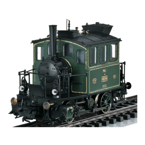
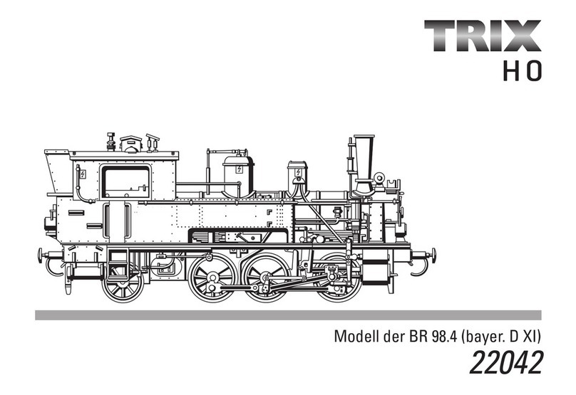
Trix D XII User manual

D GB F
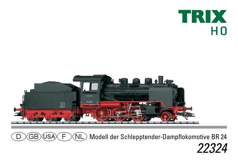
USA NL Modell der Tenderlok Gattung D XII
22840

2

3
Inhaltsverzeichnis: Seite
Informationen zum Vorbild 4
Sicherheitshinweise 6
Wichtige Hinweise 6
Multiprotokollbetrieb 6
Schaltbare Funktionen 9
Parameter/Register 10
Wartung und Instandhaltung 26
Ersatzteile 30
Table of Contents: Page
Information about the prototype 4
Safety Notes 11
Important Notes 11
Multi-Protocol Operation 11
Controllable Functions 14
Parameter/Register 15
Service and maintenance 26
Spare Parts 30
Sommaire : Page
Informations concernant la locomotive réelle 5
Remarques importantes sur la sécurité 16
Information importante 16
Mode multiprotocole 16
Fonctions commutables 19
Paramètre/Registre 20
Entretien et maintien 26
Pièces de rechange 30
Inhoudsopgave: Pagina
Informatie van het voorbeeld 5
Veiligheidsvoorschriften 21
Belangrijke aanwijzing 21
Multiprotocolbedrijf 21
Schakelbare functies 24
Parameter/Register 25
Onderhoud en handhaving 26
Onderdelen 30

4
Informationen zum Vorbild
Von der ursprünglich für den Münchner Regionalverkehr
entwickelten Tenderlok D XII mit der eigentümlichen Achsfolge
1’B2’ wurden zusätzlich zu den 106 bayerischen Maschinen
auch 31 Loks an die Pfalz-Bahn geliefert. In der gesamten
Bauzeit der Serie zwischen 1897 und 1907 wurden viele Details
weiterentwickelt oder geändert, z.B. Fenster, Kohlekasten oder
die Beleuchtung. Die als P 2.II bezeichneten pfälzischen Loko-
motiven stammen aus der Produktion von 1902 und zeigen schon
Merkmale der als Pt 2/5 N registrierten „modernen“ Teil-Serie
dieses Lok-Typs.
Die rund 69 t schweren Lokomotiven waren recht leistungsfähig
und in beiden Fahrtrichtungen bis zu 90 km/h schnell. Sowohl
D XII und P 2.II als auch Pt 2/5 N sind bei der Reichsbahn in
die Baureihe 73 aufgenommen worden, die letzten Maschinen
waren noch nach 1945 im Bestand.
Information about the Prototype
The class D XII tank locomotive with the unique 2-4-4T wheel
arrangement was originally developed for regional traffic in Mu-
nich, 31 units of this locomotive were delivered to the Palatine
Railroad in addition to the 106 Bavarian units. Many details were
developed and changed over the course of production for the
entire series between 1897 and 1907, for example: windows, coal
bunker and headlights. The Palatine locomotives were designa-
ted P 2.II, were built in 1902 and already exhibit features of the
“modern” partial series of this type of locomotive designated as
the Pt 2/5 N.
These locomotives weighed about 69 tons (metric), were quite
powerful, and reached speeds of 90 km/h (approx.
56 mph) in both directions. The D XII, P 2.II and Pt 2/5 N were
incorporated by the German State Railroad into the class 73; the
last of these units was still in the motive power pool after 1945.

5
Informations concernant la locomotive réelle
En plus des 106 exemplaires bavarois de la locomotive-tender
D XII, caractérisée par la disposition d’essieux 1’B2’, conçue à
l’origine pour le trafic régional de Munich, 31 autres locomoti-
ves furent livrées aux Chemins de fer du Palatinat. Sur toute la
période de construction de la série, qui s’étend de 1897 à 1907,
de nombreux détails furent perfectionnés ou modifiés comme
les fenêtres, la soute ou l’éclairage. Les locomotives palatines
d’appellation P 2.II sont de la production de 1902 et présentent
déjà des caractéristiques de la série partielle «moderne» de ce
type de locomotive, enregistrée comme Pt 2/5 N.
Les locomotives de 69 tonnes tout juste étaient fort puissantes
et pouvaient atteindre 90 km/h dans les deux sens de la marche.
La D XII, la P 2.II comme la Pt 2/5 N furent intégrées dans la
Reichsbahn dans la série 73, les dernières machines faisaient
encore partie du parc en 1945.
Informatie van het voorbeeld
De tenderloc D XII was oorspronkelijk voor het Münchener
regionale verkeer ontwikkeld. Van deze loc met zijn eigenzinnige
asindeling 1’B2’ werden behalve de 106 machines voor Beieren
nog 31 locs aan de Pfalz-Bahn geleverd. Gedurende de gehele
tijd dat deze loc gebouwd werd, van 1897 tot 1907, werden vele
details doorontwikkeld of veranderd, bijv. ramen, kolenkast en
de verlichting. De als P 2.II aangeduide Pfalzer locomotieven
stammen uit de productie van 1902 en laten de kenmerken van
de als Pt 2/5 N geregistreerde „moderne” deelserie van dit
loctype zien.
De rond 69 ton zware machines waren echt sterk en in beide
rijrichtingen konden ze 90 km/h halen. Zowel de D XII en de P
2.II als de Pt 2/5 N zijn bij de Reichsbahn in de serie 73 opgeno-
men. De laatste machines waren in 1945 nog in dienst.

6
Sicherheitshinweise
• DieLokdarfnurmiteinemdafürbestimmtenBetriebssystem
eingesetzt werden.
• Analogmax.15Volt=,digitalmax.22Volt~.
• DieLokdarfnurauseinerLeistungsquelleversorgtwerden.
• BeachtenSieunbedingtdieSicherheitshinweiseinder
Bedienungsanleitung zu Ihrem Betriebssystem.
• FürdenkonventionellenBetriebderLokmussdasAnschluss-
gleis entstört werden. Dazu ist das Entstörset
611 655 zu verwenden. Für Digitalbetrieb ist das Entstörset
nicht geeignet.
• ACHTUNG! Funktionsbedingte scharfe Kanten und Spitzen.
• SetzenSiedasModellkeinerdirektenSonneneinstrahlung,
starken Temperaturschwankungen oder hoher Luftfeuchtig-
keit aus.
• VerbauteLED`sentsprechenderLaserklasse1nachNormEN
60825-1.
Wichtige Hinweise
• DieBedienungsanleitungunddieVerpackungsindBestand-
teile des Produktes und müssen deshalb aufbewahrt sowie
bei Weitergabe des Produktes mitgegeben werden.
• FürReparaturenoderErsatzteilewendenSiesichbittean
Ihren Trix-Fachhändler.
• GewährleistungundGarantiegemäßderbeiliegendenGaran-
tieurkunde.
• Entsorgung:www.maerklin.com/en/imprint.html
• DervolleFunktionsumfangistnurunterTrixSystems,DCC
und unter mfx verfügbar.
• Eingebaute,fahrtrichtungsabhängigeStirnbeleuchtung.
Im Digitalbetrieb schaltbar.
• ImAnalogbetriebstehennurdieFahr-undLichtwechselfunk-
tionen zur Verfügung.
• BefahrbarerMindestradius360mm.
Multiprotokollbetrieb
Analogbetrieb
Der Decoder kann auch auf analogen Anlagen oder Gleisab-
schnitten betrieben werden. Der Decoder erkennt die analoge
Gleichspannung (DC) automatisch und passt sich der analogen
Gleisspannung an. Es sind alle Funktionen, die unter mfx oder
DCC für den Analogbetrieb eingestellt wurden aktiv (siehe
Digitalbetrieb).
Digitalbetrieb
Der Decoder ist ein Multiprotokolldecoder. Der Decoder kann unter
folgenden Digital-Protokollen eingesetzt werden: mfx oder DCC.
Das Digital-Protokoll mit den meisten Möglichkeiten ist das
höchstwertige Digital-Protokoll. Die Reihenfolge der Digital-
Protokolle ist in der Wertung fallend:
Priorität 1: mfx
Priorität 2: DCC
Priorität 3: DC
Hinweis: Werden zwei oder mehrere Digital-Protokolle am Gleis
erkannt, übernimmt der Decoder automatisch das höchstwertige
Digital-Protokoll, z.B. mfx/DCC, somit wird das mfx-Digital-Proto-
koll vom Decoder übernommen.
Hinweis: Beachten Sie, dass nicht alle Funktionen in allen
Digital-Protokollen möglich sind. Unter mfx und DCC können
einige Einstellungen von Funktionen, welche im Analog-Betrieb
wirksam sein sollen, vorgenommen werden.
7
Hinweise zum Digitalbetrieb
• DiegenaueVorgehensweisezumEinstellenderdiversen
Parameter entnehmen Sie bitte der Bedienungsanleitung
Ihrer Mehrzug-Zentrale.
• DerBetriebmitgegenpoligerGleichspannungimBremsab-
schnitt ist mit der werkseitigen Einstellung nicht möglich. Ist
diese Eigenschaft gewünscht, so muss auf den konventio-
nellenGleichstrombetriebverzichtetwerden(CV29/Bit2=0).
mfx-Protokoll
Adressierung
• KeineAdresseerforderlich,jederDecodererhälteineeinma-
lige und eindeutige Kennung (UID).
• DerDecodermeldetsichaneinerCentralStationoderMobile
Station mit seiner UID automatisch an.
• NameabWerk:Bay. D XII 2237
Programmierung
• DieEigenschaftenkönnenüberdiegrascheOberächeder
Central Station bzw. teilweise auch mit der Mobile Station
programmiert werden.
• EskönnenalleCongurationVariablen(CV)mehrfachgele-
sen und programmiert werden.
• DieProgrammierungkannentwederaufdemHaupt-oder
dem Programmiergleis erfolgen.
• DieDefaulteinstellungen(Werkseinstellungen)können
wieder hergestellt werden.
• Funktionsmapping:FunktionenkönnenmitHilfederCentral
Station 60212 (eingeschränkt) und mit der Central Station
60213/60214/60215 beliebigen Funktionstasten zugeordnet
werden (Siehe Hilfe in der Central Station).
DCC-Protokoll
Adressierung
• KurzeAdresse–LangeAdresse–Traktionsadresse
• Adressbereich:
1 - 127 kurze Adresse, Traktionsadresse
1 - 10239 lange Adresse
• JedeAdresseistmanuellprogrammierbar.
• KurzeoderlangeAdressewirdüberdieCVsausgewählt.
• EineangewandteTraktionsadressedeaktiviertdieStandard-
Adresse.

8
Programmierung
• DieEigenschaftenkönnenüberdieCongurationsVariablen
(CV) mehrfach geändert werden.
• DieCV-NummerunddieCV-Wertewerdendirekteingegeben.
• DieCVskönnenmehrfachgelesenundprogrammiertwerden
(Programmierung auf dem Programmiergleis).
• DieCVskönnenbeliebigprogrammiertwerden(Programmie-
rung auf dem Hauptgleis PoM). PoM ist nur bei den in der CV-
Tabelle gekennzeichneten CV möglich. Die Programmierung
auf dem Hauptgleis (PoM) muss von Ihrer Zentrale unterstützt
werden (siehe Bedienungsanleitung ihres Gerätes).
• DieDefaulteinstellungen(Werkseinstellungen)können
wieder hergestellt werden.
• 14bzw.28/126Fahrstufeneinstellbar.
• AlleFunktionenkönnenentsprechenddemFunktionsmapping
geschaltet werden.
• WeitereInformation,sieheCV-TabelleDCC-Protokoll.
Es wird empfohlen, die Programmierungen grundsätzlich auf
dem Programmiergleis vorzunehmen.
Logische Funktionen
Anfahr-/Bremsverzögerung
• DieBeschleunigungs-undBremszeitkanngetrenntvonei-
nander eingestellt werden.
• DielogischeFunktionsabschaltungABVkannüberdas
Funktionsmapping auf jede beliebige Funktionstaste gelegt
werden.

9
Schaltbare Funktionen
Stirnbeleuchtung an Funktion f0 Funktion f0
Betriebsgeräusch — Funktion 2 Funktion f2 Funktion f2
Geräusch: Lokpfeife — Funktion 3 Funktion f3 Funktion f3
ABV, aus — Funktion 4 Funktion f4 Funktion f4
Geräusch: Bremsenquietschen aus — Funktion 5 Funktion f5 Funktion f5
Geräusch: Rangierpfiff — Funktion 6 Funktion f6 Funktion f6
Geräusch: Dampf ablassen — Funktion 7 Funktion f7 Funktion f7
Geräusch: Luftpumpe — Funktion 8 Funktion f8 Funktion f8
Geräusch: Kohle schaufeln — — Funktion f9 Funktion f9
Geräusch: Schüttelrost — — Funktion f10 Funktion f10
Geräusch: Injektor — — Funktion f11 Funktion f11
Geräusch:Schienenstöße — — Funktion f12 Funktion f12
STOP mobile station
15
f0 f8 f0f8
f0 - f3 f4 - f7

10
CV Bedeutung Wert DCC ab Werk
1 Adresse 1 - 127 3
2 PoM Minimalgeschwindigkeit 0 - 255 4
3 PoM Anfahrverzögerung 0 - 255 13
4 PoM Bremsverzögerung 0 - 255 13
5 PoM Maximalgeschwindigkeit 0 - 255 255
8 Werkreset/Herstellerkennung 8 131
13 PoM Funktionen F1 - F8 im Analogbetrieb 0 - 255 0
14 PoM Funktionen F9 - F15 und Licht im Analogbetrieb 0 - 255 1
17 Erweiterte Adresse (oberer Teil) CV29,Bit5=1 192
18 Erweiterte Adresse (unterer Teil) CV29,Bit5=1 128
19 Traktionsadresse 0 - 255 0
21 PoM Funktionen F1 - F8 bei Traktion 0 - 255 0
22 PoM Funktionen F9 - F15 und Licht bei Traktion 0 - 255 0
29
Bit 0: Umpolung Fahrtrichtung
Bit 1: Anzahl Fahrstufen 14 oder 28/128 *
Bit 2: DCC Betrieb mit Bremsstrecke
(kein Analogbetrieb möglich)
Bit 5: Adressumfang 7 Bit / 14 Bit
0 / 1
0 / 2
0 / 4
0 / 32
0, 1, 2, 3, 4, 5, 6, 7,
32, 34, 35, 36, 37,
38, 39 6
63 Lautstärke 0 - 255 255
* Fahrstufen am Lokdecoder und am Steuergerät müssen übereinstimmen, es sind sonst Fehlfunktionen möglich.

11
• Built-inheadlightsthatchangeoverwiththedirectionof
travel. They can be turned on and off in digital operation.
• Onlythetraincontrolfunctionsandheadlightchangeover
feature are available in analog operation.
• Minimumradiusforoperationis360mm/14-3/16“.
Multi-Protocol Operation
Analog Operation
This decoder can also be operated on analog layouts or areas
of track that are analog. The decoder recognizes alternat-
ing current (DC) and automatically adapts to the analog track
voltage. All functions that were set under mfx or DCC for analog
operation are active (see Digital Operation).
Digital Operation
The decoders are multi-protocol decoders. These decoders can
be used under the following digital protocols: mfx or DCC.
The digital protocol with the most possibilities is the highest
order digital protocol. The sequence of digital protocols in
descending order is:
Priority 1: mfx
Priority 2: DCC
Priority 3: DC
Note: If two or more digital protocols are recognized in the track,
the decoder automatically takes on the highest order digital
protocol, example: mfx/DCC; the decoder takes on the mfx digital
protocol (see previous table).
Note: Please note that not all functions are possible in all digital
protocols. Several settings for functions, which are supposed to
be active in analog operation, can be done under mfx and DCC.
Safety Notes
• Thislocomotiveisonlytobeusedwiththeoperatingsystem
it is designed for.
• Analogmax.15voltsDC,digitalmax.22voltsAC.
• Thislocomotivemustneverbesuppliedwithpowerfrom
more than one power pack.
• Pleasemakenoteofthesafetynotesintheinstructionsfor
your operating system.
• Thefeedertrackmustbeequippedtopreventinterference
with radio and television reception, when the locomotive is
to be run in conventional operation. The 611 655 interference
suppression set is to be used for this purpose. The interfe-
rence suppression set is not suitable for digital operation.
• WARNING! Sharp edges and points required for operation.
• Donotexposethemodeltodirectsunlight,extremechanges
in temperature, or high humidity.
• TheLEDsinthisitemcorrespondtoLaserClass1according
to Standard EN 60825-1.
Important Notes
• Theoperatinginstructionsandthepackagingareacompo-
nent part of the product and must therefore be kept as well as
transferred along with the product to others.
• PleaseseeyourauthorizedTrixdealerforrepairsorspare
parts.
• Thewarrantycardincludedwiththisproductspeciesthe
warranty conditions.
• Disposing:www.maerklin.com/en/imprint.html
• ThefullrangeoffunctionsisonlyavailableunderTrixSys-
tems and under DCC.

12
Notes on digital operation
• Theoperatinginstructionsforyourcentralunitwillgiveyou
exact procedures for setting the different parameters.
• Thesettingdoneatthefactorydoesnotpermitoperationwith
opposite polarity DC power in the braking block. If you want
this characteristic, you must do without conventional DC
poweroperation(CV29/Bit2=0).
mfx Protocol
Addresses
• Noaddressisrequired;eachdecoderisgivenaone-time,
unique identifier (UID).
• ThedecoderautomaticallyregistersitselfonaCentralStation
or a Mobile Station with its UID.
• Namesetatthefactory:Bay. D XII 2237
Programming
• Thecharacteristicscanbeprogrammedusingthegraphic
screen on the Central Station or also partially with the Mobile
Station.
• AlloftheCongurationVariables(CV)canbereadand
programmed repeatedly.
• Theprogrammingcanbedoneeitheronthemaintrackorthe
programming track.
• Thedefaultsettings(factorysettings)canbeproduced
repeatedly.
• Functionmapping:Functionscanbeassignedtoanyofthe
function buttons with the help of the 60212 Central Station
(with limitations) and with the 60213/60214/60215 Central Sta-
tion (See help section in the Central Station).
DCC Protocol
Addresses
• Shortaddress–longaddress–multipleunitaddress
• Addressrange:
1 - 127 for short address and multiple unit address,
1 - 10239 for long address
• Everyaddresscanbeprogrammedmanually.
• AshortoralongaddressisselectedusingtheCVs.
• Amultipleunitaddressthatisbeinguseddeactivatesthe
standard address.

13
Programming
• Thecharacteristicscanbechangedrepeatedlyusingthe
Configuration Variables (CV).
• TheCVnumbersandtheCVvaluesareentereddirectly.
• TheCVscanbereadandprogrammedrepeatedly.(Program-
ming is done on the programming track.)
• TheCVscanbeprogrammedinanyorderdesired.(Program-
ming can be done on the main track PoM). The PoM can only
be done with those designated in the CV table. Programming
on the main track PoM must be supported by your central
controller (Please see the description for this unit.).
• Thedefaultsettings(factorysettings)canbeproduced
repeatedly.
• 14/28or126speedlevelscanbeset.
• Allofthefunctionscanbecontrolledaccordingtothefunc-
tion mapping (see CV description).
• SeetheCVdescriptionfortheDCCprotocolforadditional
information.
We recommend that in general programming should be done on
the programming track.
Logic Functions
Acceleration/Braking Delay
• Theaccelerationandbrakingtimecanbesetseparatelyfrom
each other.
• ThelogicfunctionABVcanbeassignedtoanyfunction
button by using the function mapping.

14
Controllable Functions
Headlights on Function f0 Function f0
Operating sounds — Function 2 Function f2 Function f2
Sound effect: Locomotive whistle — Function 3 Function f3 Function f3
ABV, off — Function 4 Function f4 Function f4
Sound effect: Squealing brakes off — Function 5 Function f5 Function f5
Sound effect: Switching whistle — Function 6 Function f6 Function f6
Sound effect: Blowing off steam — Function 7 Function f7 Function f7
Sound effect: Air pump — Function 8 Function f8 Function f8
Sound effect: Coal being shoveled — — Function f9 Function f9
Sound effect: Rocker grate — — Function f10 Function f10
Sound effect: Injector — — Function f11 Function f11
Sound effect: Rail joints — — Function f12 Function f12
f0 - f3 f4 - f7
STOP mobile station
15
f0 f8 f0f8

15
CV Discription DCC Value Factory-Set
1 Address 1 - 127 3
2 PoM Minimum Speed 0 - 255 4
3 PoM Acceleration delay 0 - 255 13
4 PoM Braking delay 0 - 255 13
5 PoM Maximum speed 0 - 255 255
8 Factory Reset / Manufacturer Recognition 8 131
13 PoM Functions F1 - F8 in analog operation 0 - 255 0
14 PoM Functions F9 - F15 and lights in analog operation 0 - 255 1
17 Extended address (upper part) CV29,Bit5=1 192
18 Extended address (lower part) CV29,Bit5=1 128
19 Multiple Unit Address 0 - 255 0
21 PoM Functions F1 - F8 on Multiple Unit 0 - 255 0
22 PoM Functions F9 - F15 and lights on Multiple Unit 0 - 255 0
29
Bit 0: Reversing direction
Bit 1: Number of speed levels 14 or 28/128 *
Bit 2: DCC operation with braking area
(no analog operation possible)
Bit 5: Address length 7 Bit / 14 Bit
0 / 1
0 / 2
0 / 4
0 / 32
0, 1, 2, 3, 4, 5, 6, 7,
32, 34, 35, 36, 37,
38, 39
6
63 Volume 0 - 255 255
* The speed levels on the locomotive decoder and on the controller must agree with each other; otherwise, you may have malfunctions.

16
Remarques importantes sur la sécurité
• Lalocomotivenepeutêtreutiliséequ‘aveclesystème
d‘exploitationindiqué.
• Analogiquemax.15Volt=,digitalmax.22Volt~.
• Lalocomotivenepeutpasêtrealimentéeélectriquementpar
plusd‘unesourcedecourantàlafois.
• Ilestimpératifdetenircomptedesremarquessurla
sécuritédécritesdanslemoded‘emploidevotresystème
d‘exploitation.
•
Pour l’exploitation de la locomotive en mode conventionnel, la
voie de raccordement doit être déparasitée. A cet effet, utili-
ser le set de déparasitage réf. 611 655. Le set de déparasitage
ne convient pas pour l’exploitation en mode numérique.
•
ATTENTION! Pointes et bords coupants lors du fonctionnement
du produit.
•
Ne pas exposer le modèle à un ensoleillement direct, à de fortes
variationsdetempératureouàuntauxd‘humiditéimportant.
• LesDELinstalléescorrespondentàlaclasselaser1selonla
norme EN 60825-1.
Information importante
• Lanoticed‘utilisationetl’emballagefontpartieintégrantedu
produit ; ils doivent donc être conservés et, le cas échéant,
transmis avec le produit.
• Pourtouteréparationouremplacementdepièces,adressez
vous à votre détaillant-spécialiste Trix.
• Garantielégaleetgarantiecontractuelleconformémentau
certificat de garantie ci-joint.
• Elimination:www.maerklin.com/en/imprint.html
• L’intégralitédesfonctionsestdisponibleuniquementen
exploitation Trix Systems, DCC et mfx.
• Feuxdesignalisations‘inversantselonlesensdemarche;
feux commutables en exploitation digital.
• Enmoded’exploitationanalogique,seuleslesfonctionsrela-
tivesàlaconduiteetàl‘inversiondesfeuxsontdisponibles.
• Rayonminimald’inscriptionencourbe360mm.
Mode multiprotocole
Mode analogique
On peut aussi faire fonctionner le décodeur sur des installations
ou des sections de voie analogiques. Le décodeur identifie
automatiquement la tension de voie analogique (CC). Toutes les
fonctions qui ont été paramétrée pour le mode analogique sous
mfx ou sous DCC sont actives (voir mode numérique).
Mode numérique
Les décodeur sont des décodeur multiprotocole. Le décodeur peut
être utilisé avec les protocoles numériques suivants : mfx, DCC
Le protocole numérique offrant les possibilités les plus
nombreuses est le protocole numérique à bit de poids fort. La
hiérarchisation des protocoles numériques est descendante :
Priorité 1 : mfx
Priorité 2 : DCC
Priorité 3 :
DC
Indication : lorsque deux ou plusieurs protocoles numériques
sont identifiés au niveau de la voie, le décodeur reprend
automatiquement le protocole numérique à bit de poids fort, p.
ex. mfx/DCC. Le protocole numérique mfx est donc repris par le
décodeur (voir tableau antérieur).

17
Indication : remarquez que toutes les fonctions ne peuvent
pas être actionnées dans tous les protocoles numériques.
Sous mfx et sous DCC, il est possible de procéder à quelques
paramétrages de fonctions devant être actives dans le cadre de
l’exploitation analogique.
Remarques relatives au fonctionnement en mode
digital
• Encequiconcernelaprocédurederéglagedesdivers
paramètres,veuillezvousréféreraumoded‘emploidevotre
centrale de commande multitrain.
• L’exploitationaveccourantcontinudepolaritéinversedans
les sections de freinage n’est pas possible avec le réglage
d’usine. Si cette propriété est désirée, il faut alors renoncer à
l’exploitation conventionnelle en courant continu
(CV29/Bit2=0).
Protocole mfx
Adressage
• Aucuneadressen’estnécessaire,ledécodeurreçoittoute-
fois une identification unique et non équivoque (UID).
• AvecsonUID,ledécodeurindiqueautomatiquementàune
station centrale ou à une station mobile qu’il est connecté.
• Nomencodeeenusine:Bay. D XII 2237
Programmation
• Lescaractéristiquespeuventêtreprogramméesparl’inter-
médiaire de la couche graphique de la station centrale, voire
en partie aussi au moyen de la station mobile.
• Touteslescongurationsvariables(CV)peuventêtrelueset
programmées de façon réitérée.
• Laprogrammationpeutêtreréaliséesoitsurlavoieprinci-
pale, soit sur la voie de programmation.
• Lesparamétragespardéfaut(paramétragesusine)peuvent
être rétablis.
• Mappagedesfonctions:lesfonctionspeuventêtreaffectées
à de quelconques touches de fonction au moyen de la station
centrale (60212) (restreinte) et avec la station centrale
60213/60214/60215 (voir Aide au niveau de la station centrale).
Protocole DCC
Adressage
• Adressebrève–adresselongue–adressedetraction.
• Champd’adresse:
1–127adressebrève,adressedetraction
1–10239adresselongue
• Chaqueadresseestprogrammablemanuellement.
• L’adressebrèveoulongueestchoisieparl’intermédiairedesCVs.
• Uneadressedetractionutiliséedésactivel’adressestandard.

18
Programmation
•
Les caractéristiques peuvent être modifiées de façon réitérée
par l’intermédiaire des variables de configuration (CVs).
• Touteslescongurationsvariables(CV)peuventêtrelueset
programmées de façon réitérée.
• Laprogrammationpeutêtreréaliséesoitsurlavoieprinci-
pale, soit sur la voie de programmation.
• LesCVspeuventêtreprogramméeslibrement(programma-
tion de la voie principale (PoM). La PoM n’est possible que
pour les CVs identifiées dans le tableau des CVs. La program-
mation sur la voie principale (PoM) doit être supportée par
votre centrale (voir mode d’emploi de votre appareil).
• Lesparamétragespardéfaut(paramétragesusine)peuvent
être rétablis.
• 14/28,voire126cransdemarchesontparamétrables.
• Touteslesfonctionspeuventêtrecommutéesenfonctiondu
mappage des fonctions (voir le descriptif des CVs).
• Pourtouteinformationcomplémentaire,voirletableaudes
CVs, protocole DCC.
Il est recommandé, de réaliser la programmation, fondamentale-
ment, sur la voie de programmation.
Fonctions logiques
Retard au démarrage / au freinage
• Lestempsd’accélérationetdefreinagepeuventêtreparamé-
trés séparément les uns des autres.
• Parl’intermédiairedumappagedesfonctions,lamisehors
fonction de la fonction logique ABV peut être affectée à
n’importe quelle touche de fonction.

19
Fonctions commutables
Fanal activé Fonction f0 Fonction f0
Bruit d’exploitation — Fonction 2 Fonction f2 Fonction f2
Bruitage:Sifetlocomotive — Fonction 3 Fonction f3 Fonction f3
ABV, désactivé — Fonction 4 Fonction f4 Fonction f4
Bruitage : Grincement de freins désactivé — Fonction 5 Fonction f5 Fonction f5
Bruitage:Sifetpourmanœuvre
— Fonction 6 Fonction f6 Fonction f6
Bruitage : Échappement de la vapeur — Fonction 7 Fonction f7 Fonction f7
Bruitage : Compresseur — Fonction 8 Fonction f8 Fonction f8
Bruitage : Pelletage du charbon — — Fonction f9 Fonction f9
Bruitage : Grille à secousses — — Fonction f10 Fonction f10
Bruitage : Injecteur — — Fonction f11 Fonction f11
Bruitage : joints de rail — — Fonction f12 Fonction f12
f0 - f3 f4 - f7
STOP mobile station
15
f0 f8 f0f8

20
CV Affection DCC Valeur Parm. Usine
1 Adresse 1 - 127 3
2 PoM Vitesse min 0 - 255 4
3 PoM Temporisationd‘accélération 0 - 255 13
4 PoM Temporisation de freinage 0 - 255 13
5 PoM Vitesse maximale 0 - 255 255
8 Réinitialisation d’usine/identification du fabricant 8 131
13 PoM Fonctions F1 - F8 en mode analog 0 - 255 0
14 PoM Fonctions F9 - F15 et éclairage en mode analog 0 - 255 1
17 Adresse étendue (partie supérieure) CV29,Bit5=1 192
18 Adresse étendue (partie inférieure) CV29,Bit5=1 128
19 Adresse traction 0 - 255 0
21 PoM Fonctions F1 - F8 pour traction 0 - 255 0
22 PoM Fonctions F9 - F15 et éclairage traction 0 - 255 0
29
Bit 0: Inv. polarité Sens de marche
Bit 1: Nombre de crans de marche 14 ou 28/128 *
Bit 2:
Mode DCC avec dist. de freinage (mode analog impossible)
Bit 5: Capacité d’adresses 7 Bit / 14 Bit
0 / 1
0 / 2
0 / 4
0 / 32
0, 1, 2, 3, 4, 5, 6, 7,
32, 34, 35, 36, 37,
38, 39 6
63 Volume 0 - 255 255
* Pour éviter tout dysfonctionnement, les crans de marche sur le décodeur de loco doivent impérativement coïncider avec ceux de
l’appareil de commande.
This manual suits for next models
1
Table of contents
Languages:
Other Trix Toy manuals

Trix
Trix BB 15000 Series User manual

Trix
Trix VT98 DB User manual

Trix
Trix EL 10 User manual

Trix
Trix Triebzuges ET 87 User manual

Trix
Trix ER 20 EVB User manual

Trix
Trix Velaro User manual

Trix
Trix H0 5519 User manual

Trix
Trix Minitrix 66540 User manual

Trix
Trix Rheingold User manual

Trix
Trix 22141 User manual
Popular Toy manuals by other brands

Fisher-Price
Fisher-Price T6339 instruction sheet

Playskool
Playskool Magic Screen Learning Pal 03488 instruction manual

Hasbro
Hasbro Transformers 83749 instruction manual

Italeri
Italeri 1356 instructions

FISCHER
FISCHER Fischertechnik FUN CARS BASIC manual

Legend Hobby
Legend Hobby 86'' A-1 SKYRAIDER 35-60cc WARBIRD Assembly manual