Trix H0 D XII User manual

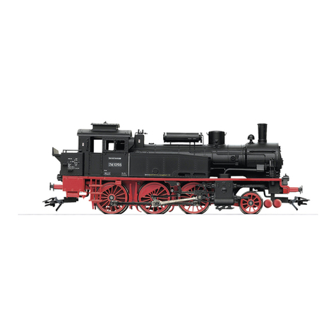
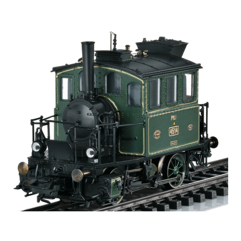
Modell der D XII
22839

2
Inhaltsverzeichnis: Seite
Informationen zum Vorbild 4
Betriebshinweise 6
Sicherheitshinweise 6
Wichtige Hinweise 6
Funktionen 6
Schaltbare Funktionen 7
CVs und Parameter 8
Wartung und Instandhaltung 30
Ersatzteile 34
Table of Contents: Page
Information about the prototype 4
Information about operation 9
Safety Notes 9
Important Notes 9
Functions 9
Controllable Functions 10
CVs and Parameters 11
Service and maintenance 30
Spare Parts 34
Sommaire : Page
Informations concernant la locomotive réelle 5
Remarques sur l’exploitation 12
Remarques importantes sur la sécurité 12
Information importante 12
Fonctionnement 12
Fonctions commutables 13
CVs et paramètres 14
Entretien et maintien 30
Pièces de rechange 34
Inhoudsopgave: Pagina
Informatie van het voorbeeld 5
Opmerkingen over de werking 15
Veiligheidsvoorschriften 15
Belangrijke aanwijzing 15
Functies 15
Schakelbare functies 16
CV’s en parameter 17
Onderhoud en handhaving 30
Onderdelen 34

3
Indice de contenido: Página
Instrucciones de uso 18
Aviso de seguridad 18
Notas importantes 18
Funciones 18
Funciones posibles 19
CVs y parámetros 20
El mantenimiento 30
Recambios 34
Indice del contenuto: Pagina
Avvertenze per il funzionamento 21
Avvertenze per la sicurezza 21
Avvertenze importanti 21
Funzioni 21
Funzioni commutabili 22
CV e parametri 23
Manutenzione ed assistere 30
Pezzi di ricambio 34
Innehållsförteckning: Sida
Driftanvisningar 24
Säkerhetsanvisningar 24
Viktig information 24
Funktioner 24
Kopplingsbara funktioner 25
CV och parametrar 26
Underhåll och reparation 30
Reservdelar 34
Indholdsfortegnelse: Side
Brugsanvisninger 6
Vink om sikkerhed 27
Vigtige bemærkninger 27
Funktioner 27
Styrbare funktioner 28
CV‘er og parametre 29
Service og reparation 30
Reservedele 34

4
Informationen zum Vorbild
Von der ursprünglich für den Münchner Regionalverkehr
entwickelten Tenderlok D XII mit der eigentümlichen Achsfolge
1’B2’ wurden zusätzlich zu den 106 bayerischen Maschinen
auch 31 Loks an die Pfalz-Bahn geliefert. In der gesamten
Bauzeit der Serie zwischen 1897 und 1907 wurden viele Details
weiterentwickelt oder geändert, z.B. Fenster, Kohlekasten oder
die Beleuchtung. Die als P 2.II bezeichneten pfälzischen Loko-
motiven stammen aus der Produktion von 1902 und zeigen schon
Merkmale der als Pt 2/5 N registrierten „modernen“ Teil-Serie
dieses Lok-Typs.
Die rund 69 t schweren Lokomotiven waren recht leistungsfähig
und in beiden Fahrtrichtungen bis zu 90 km/h schnell. Sowohl
D XII und P 2.II als auch Pt 2/5 N sind bei der Reichsbahn in
die Baureihe 73 aufgenommen worden, die letzten Maschinen
waren noch nach 1945 im Bestand.
Information about the Prototype
The class D XII tank locomotive with the unique 2-4-4T wheel
arrangement was originally developed for regional traffic in Mu-
nich, 31 units of this locomotive were delivered to the Palatine
Railroad in addition to the 106 Bavarian units. Many details were
developed and changed over the course of production for the
entire series between 1897 and 1907, for example: windows, coal
bunker and headlights. The Palatine locomotives were designa-
ted P 2.II, were built in 1902 and already exhibit features of the
“modern” partial series of this type of locomotive designated as
the Pt 2/5 N.
These locomotives weighed about 69 tons (metric), were quite
powerful, and reached speeds of 90 km/h (approx. 56 mph) in
both directions. The D XII, P 2.II and Pt 2/5 N were incorporated
by the German State Railroad into the class 73; the last of these
units was still in the motive power pool after 1945.

5
Informations concernant la locomotive réelle
En plus des 106 exemplaires bavarois de la locomotive-tender
D XII, caractérisée par la disposition d’essieux 1’B2’, conçue à
l’origine pour le trafic régional de Munich, 31 autres locomoti-
ves furent livrées aux Chemins de fer du Palatinat. Sur toute la
période de construction de la série, qui s’étend de 1897 à 1907,
de nombreux détails furent perfectionnés ou modifiés comme
les fenêtres, la soute ou l’éclairage. Les locomotives palatines
d’appellation P 2.II sont de la production de 1902 et présentent
déjà des caractéristiques de la série partielle «moderne» de ce
type de locomotive, enregistrée comme Pt 2/5 N.
Les locomotives de 69 tonnes tout juste étaient fort puissantes
et pouvaient atteindre 90 km/h dans les deux sens de la marche.
La D XII, la P 2.II comme la Pt 2/5 N furent intégrées dans la
Reichsbahn dans la série 73, les dernières machines faisaient
encore partie du parc en 1945.
Informatie van het voorbeeld
De tenderloc D XII was oorspronkelijk voor het Münchener
regionale verkeer ontwikkeld. Van deze loc met zijn eigenzinnige
asindeling 1’B2’ werden behalve de 106 machines voor Beieren
nog 31 locs aan de Pfalz-Bahn geleverd. Gedurende de gehele
tijd dat deze loc gebouwd werd, van 1897 tot 1907, werden vele
details doorontwikkeld of veranderd, bijv. ramen, kolenkast en
de verlichting. De als P 2.II aangeduide Pfalzer locomotieven
stammen uit de productie van 1902 en laten de kenmerken van
de als Pt 2/5 N geregistreerde “moderne” deelserie van dit
loctype zien.
De rond 69 ton zware machines waren echt sterk en in beide
rijrichtingen konden ze 90 km/h halen. Zowel de D XII en de P 2.II
als de Pt 2/5 N zijn bij de Reichsbahn in de serie 73 opgenomen.
De laatste machines waren in 1945 nog in dienst.

6
Sicherheitshinweise
• DieLokdarfnurmiteinemdafürbestimmtenBetriebssystem
eingesetzt werden.
• Analogmax.15Volt=,digitalmax.22Volt~.
• DieLokdarfnurauseinerLeistungsquelleversorgtwerden.
• BeachtenSieunbedingtdieSicherheitshinweiseinderBedie-
nungsanleitung zu Ihrem Betriebssystem.
•FürdenkonventionellenBetriebderLokmussdasAnschluss-
gleis entstört werden. Dazu ist das Entstörset 611 655 zu ver-
wenden. Für Digitalbetrieb ist das Entstörset nicht geeignet.
• ACHTUNG! Funktionsbedingte scharfe Kanten und Spitzen.
•SetzenSiedasModellkeinerdirektenSonneneinstrahlung,
starken Temperaturschwankungen oder hoher Luftfeuchtigkeit
aus.
Wichtige Hinweise
•DieBedienungsanleitungunddieVerpackungsindBestandteile
des Produktes und müssen deshalb aufbewahrt sowie bei
Weitergabe des Produktes mitgegeben werden.
•FürReparaturenoderErsatzteilewendenSiesichbittean
Ihren Trix-Fachhändler.
•GewährleistungundGarantiegemäßderbeiliegendenGaran-
tieurkunde.
•http://www.maerklin.com/en/imprint.html
Funktionen
• EingebauteElektronikzumwahlweisenBetriebmitkonventio-
nellem Gleichstrom-Fahrgerät, Trix Systems oder Digitalsyste-
men nach NMRA-Norm.
• AutomatischeSystemerkennungzwischenDigital-und
Analog-Betrieb.
•DervolleFunktionsumfangistnurunterTrixSystemsundunter
DCC verfügbar.
• Eingebaute,fahrtrichtungsabhängigeStirnbeleuchtung.
Im Digitalbetrieb schaltbar.
•BefahrbarerMindestradius360mm.
Hinweise zum Digitalbetrieb
• DiegenaueVorgehensweisezumEinstellenderdiversen
Parameter entnehmen Sie bitte der Bedienungsanleitung Ihrer
Mehrzug-Zentrale.
•DieabWerkeingestelltenWertesindsogewählt,dassbest-
möglichstes Fahrverhalten gewährleistet ist.
• DerBetriebmitgegenpoligerGleichspannungimBremsab-
schnitt ist mit der werkseitigen Einstellung nicht möglich. Ist
diese Eigenschaft gewünscht, so muss auf den konventio-
nellenGleichstrombetriebverzichtetwerden(CV29/Bit2=0).

7
Schaltbare Funktionen
Stirnbeleuchtung an Funktion f0 Funktion f0
ABV, aus — Funktion f4 Funktion f4 Funktion f4
STOP mobile station
systems
15
f0 f8 f0f8
f0 - f3 f4 - f7

8
CV Bedeutung Wert DCC ab Werk
1 Adresse 1 - 127 3
2 PoM Minimalgeschwindigkeit 0 - 255 15
3 PoM Anfahrverzögerung 0 - 255 6
4 PoM Bremsverzögerung 0 - 255 4
5 PoM Maximalgeschwindigkeit 0 - 255 235
8 Werkreset/Herstellerkennung 8 131
13 PoM Funktionen F1 - F8 im Analogbetrieb 0 - 255 0
14 PoM Funktionen F9 - F15 und Licht im Analogbetrieb 0 - 255 1
17 Erweiterte Adresse (oberer Teil) CV29,Bit5=1 192
18 Erweiterte Adresse (unterer Teil) CV29,Bit5=1 128
19 Traktionsadresse 0 - 255 0
21 PoM Funktionen F1 - F8 bei Traktion 0 - 255 0
22 PoM Funktionen F9 - F15 und Licht bei Traktion 0 - 255 0
29
Bit 0: Umpolung Fahrtrichtung
Bit 1: Anzahl Fahrstufen 14 oder 28/128
Bit 2: DCC Betrieb mit Bremsstrecke
(kein Analogbetrieb möglich)
Bit 5: Adressumfang 7 Bit / 14 Bit
0 / 1
0 / 2
0 / 4
0 / 32
***
0, 1, 2, 3, 4, 5, 6, 7,
32, 34, 35, 36, 37,
38, 39
6
PoM Program on the Main; muss vom Steuergerät unterstützt werden.
*** Die Werte der gewünschten Einstellungen sind zu addieren!

9
Functions
• Built-inelectroniccircuitforoperationwithaconventionalDC
power pack, Trix Systems or NMRA DCC digital systems.
• Automaticsystemrecognitionbetweendigitalandanalog
operation.
•ThefullrangeoffunctionsisonlyavailableunderTrixSystems
and under DCC.
• Built-inheadlightsthatchangeoverwiththedirectionof
travel. They can be turned on and off in digital operation.
•Minimumradiusforoperationis360mm/14-3/16“.
Notes on digital operation
•Theoperatinginstructionsforyourcentralunitwillgiveyou
exact procedures for setting the different parameters.
• Thevaluessetatthefactorywereselectedtoguaranteethe
best possible running characteristics.
• Thesettingdoneatthefactorydoesnotpermitoperation
with opposite polarity DC power in the braking block. If you
want this characteristic, you must do without conventional DC
poweroperation(CV29/Bit2=0).
Safety Notes
• Thislocomotiveisonlytobeusedwiththeoperatingsystemit
is designed for.
• Analogmax.15voltsDC,digitalmax.22voltsAC.
• Thislocomotivemustneverbesuppliedwithpowerfrommore
than one power pack.
• Pleasemakenoteofthesafetynotesintheinstructionsfor
your operating system.
•Thefeedertrackmustbeequippedtopreventinterference
with radio and television reception, when the locomotive is
to be run in conventional operation. The 611 655 interference
suppression set is to be used for this purpose. The interfe-
rence suppression set is not suitable for digital operation.
• WARNING! Sharp edges and points required for operation.
•Donotexposethemodeltodirectsunlight,extremechanges
in temperature, or high humidity.
Important Notes
•Theoperatinginstructionsandthepackagingareacompo-
nent part of the product and must therefore be kept as well as
transferred along with the product to others.
•PleaseseeyourauthorizedTrixdealerforrepairsorspare
parts.
•Thewarrantycardincludedwiththisproductspeciesthe
warranty conditions.
•http://www.maerklin.com/en/imprint.html

10
Controllable Functions
Headlights on Function f0 Function f0
ABV, off — Function f4 Function f4 Function f4
STOP mobile station
systems
15
f0 f8 f0f8
f0 - f3 f4 - f7

11
PoM Program on the Main; must be supported by the controller
*** The values for the desired settings must be added.
CV Discription DCC Value Factory-Set
1 Address 1 - 127 3
2 PoM Minimum Speed 0 - 255 15
3 PoM Acceleration delay 0 - 255 6
4 PoM Braking delay 0 - 255 4
5 PoM Maximum speed 0 - 255 235
8 Factory Reset / Manufacturer Recognition 8 131
13 PoM Functions F1 - F8 in analog operation 0 - 255 0
14 PoM Functions F9 - F15 and lights in analog operation 0 - 255 1
17 Extended address (upper part) CV29,Bit5=1 192
18 Extended address (lower part) CV29,Bit5=1 128
19 Multiple Unit Address 0 - 255 0
21 PoM Functions F1 - F8 on Multiple Unit 0 - 255 0
22 PoM Functions F9 - F15 and lights on Multiple Unit 0 - 255 0
29
Bit 0: Reversing direction
Bit 1: Number of speed levels 14 or 28/128
Bit 2: DCC operation with braking area
(no analog operation possible)
Bit 5: Address length 7 Bit / 14 Bit
0 / 1
0 / 2
0 / 4
0 / 32
***
0, 1, 2, 3, 4, 5, 6, 7,
32, 34, 35, 36, 37,
38, 39
6

12
Remarques importantes sur la sécurité
• Lalocomotivenepeutêtreutiliséequ‘aveclesystème
d‘exploitation indiqué.
• Analogiquemax.15Volt=,digitalmax.22Volt~.
• Lalocomotivenepeutpasêtrealimentéeélectriquementpar
plus d‘une source de courant à la fois.
• Ilestimpératifdetenircomptedesremarquessurla
sécurité décrites dans le mode d‘emploi de votre système
d‘exploitation.
•
Pour l’exploitation de la locomotive en mode conventionnel, la
voie de raccordement doit être déparasitée. A cet effet, utiliser
le set de déparasitage réf. 611 655. Le set de déparasitage ne
convient pas pour l’exploitation en mode numérique.
•
ATTENTION! Pointes et bords coupants lors du fonctionnement
du produit.
•Nepasexposerlemodèleàunensoleillementdirect,àde
fortes variations de température ou à un taux d‘humidité
important.
Information importante
•Lanoticed‘utilisationetl’emballagefontpartieintégrantedu
produit ; ils doivent donc être conservés et, le cas échéant,
transmis avec le produit.
•Pourtouteréparationouremplacementdepièces,adressez
vous à votre détaillant-spécialiste Trix.
•Garantielégaleetgarantiecontractuelleconformémentau
certificat de garantie ci-joint.
•http://www.maerklin.com/en/imprint.html
Fonctionnement
• Electroniqueintégréepourexploitationauchoixavectransforma-
teur-régulateur conventionnel délivrant du courant continu, avec
Trix Systems ou avec des systèmes de conduite digitale conformes
aux normes NMRA.
• Reconnaissanceautomatiquedusystèmeentreexploitations
numérique et analogique.
•L’intégralitédesfonctionsestdisponibleuniquementen
exploitation Trix Systems et DCC.
• Feuxdesignalisations‘inversantselonlesensdemarche;
feux commutables en exploitation digital.
•Rayonminimald’inscriptionencourbe360mm.
Remarques relatives au fonctionnement en mode digital
•Encequiconcernelaprocédurederéglagedesdivers
paramètres, veuillez vous référer au mode d‘emploi de votre
centrale de commande multitrain.
•Lesvaleursparamétréesd’usinesontchoisiesdemanièreà
garantir le meilleur comportement de roulement possible.
•
L’exploitation avec courant continu de polarité inverse dans les
sections de freinage n’est pas possible avec le réglage d’usine. Si
cette propriété est désirée, il faut alors renoncer à l’exploitation
conventionnelleencourantcontinu(CV29/Bit2=0).

13
Fonctions commutables
Fanal activé Fonction f0 Fonction f0
ABV, désactivé — Fonction f4 Fonction f4 Fonction f4
STOP mobile station
systems
15
f0 f8 f0f8
f0 - f3 f4 - f7

14
PoM Program on the Main; doit être pris en charge par l’appareil de commande.
*** Les valeurs des réglages désirés sont à additioner.
CV Affectation DCC Valeur Parm. Usine
1 Adresse 1 - 127 3
2 PoM Vitesse minimale 0 - 255 15
3 PoM Temporisation d‘accélération 0 - 255 6
4 PoM Temporisation de freinage 0 - 255 4
5 PoM Vitesse maximale 0 - 255 235
8 Réinitialisation d’usine/identification du fabricant 8 131
13 PoM Fonctions F1 - F8 en mode analogique 0 - 255 0
14 PoM Fonctions F9 - F15 et éclairage en mode analogique 0 - 255 1
17 Adresse étendue (partie supérieure) CV29,Bit5=1 192
18 Adresse étendue (partie inférieure) CV29,Bit5=1 128
19 Adresse traction 0 - 255 0
21 PoM Fonctions F1 - F8 pour traction 0 - 255 0
22 PoM Fonctions F9 - F15 et éclairage traction 0 - 255 0
29
Bit 0: Inv. polarité Sens de marche
Bit 1: Nombre de crans de marche 14 ou 28/128
Bit 2: Mode DCC avec dist. de freinage (pas possible en mode analogique)
Bit 5: Capacité d’adresses 7 Bit / 14 Bit
0 / 1
0 / 2
0 / 4
0 / 32
***
0, 1, 2, 3, 4, 5, 6,
7, 32, 34, 35, 36,
37, 38, 39
6

15
Veiligheidsvoorschriften
• Delocmagalleenmeteendaarvoorbestemdbedrijfssysteem
gebruikt worden.
• Analoogmax.15Volt=,digitaalmax.22Volt~.
• Delocmagnietvanuitmeerdanéénstroomvoorziening
gelijktijdig gevoed worden.
• Leesookaandachtigdeveiligheidsvoorschriftenindege-
bruiksaanwijzing van uw bedrijfssysteem.
•Voorhetconventionelebedrijfmetdelocdientdeaansluitrail
te worden ontstoort. Hiervoor dient men de ontstoor-set
611 655 te gebruiken. Voor het digitale bedrijf is deze ontstoor-
set niet geschikt.
• OPGEPAST! Functionele scherpe kanten en punten.
•Stelhetmodelnietblootaanindirectezonnestraling,sterke
temperatuurwisselingen of hoge luchtvochtigheid.
Belangrijke aanwijzing
•Degebruiksaanwijzingendeverpakkingzijneenbestanddeel
van het product en dienen derhalve bewaard en meegeleverd
te worden bij het doorgeven van het product.
•VoorreparatiesenonderdelenkuntzichtotUwTrixhandelaar
wenden.
•Vrijwaringengarantieovereenkomstighetbijgevoegdegaran-
tiebewijs.
•http://www.maerklin.com/en/imprint.html
Functies
• Ingebouwdeelektronicadiehetmogelijkmaaktomnaarkeuze
met, een conventionele gelijkstroomrijregelaar, Trix Systems of
digitaalsysteem volgens NMRA-norm te rijden.
• Automatischesysteemherkenningtussendigitaal-enanaloog-
bedrijf.
•Devolledigetoegangtotallefunctiesisalleenmogelijkmet
Trix Systems of met DCC bedrijf.
• Ingebouwde,rijrichtingsafhankelijkefrontverlichtingisinhet
digitaalsysteem schakelbaar.
•Minimaleteberijdenradius:360mm.
Aanwijzingen voor digitale besturing
•Hetopdejuistewijzeinstellenvandediverseparameters
staat beschreven in de handleiding van uw digitale Centrale.
•Devanafdefabriekingesteldewaardenzijnzoingestelddat
de rij-eigenschappen optimaal zijn.
• Hetbedrijfmettegengepooldegelijkspanningindeafrem-
sectie is met de fabrieksinstelling niet mogelijk. Indien deze
eigenschap wenselijk is, dan moet worden afgezien van het
conventioneelgelijkstroombedrijf(CV29/Bit2=0).

16
Schakelbare functies
Frontverlichting aan Functie f0 Functie f0
ABV, uit — Functie f4 Functie f4 Functie f4
STOP mobile station
systems
15
f0 f8 f0f8
f0 - f3 f4 - f7

17
PoM Program on the Main; dient door het besturingsapparaat ondersteunt te worden.
*** De waarde van de gewenste instellingen moeten bij elkaar opgeteld worden.
CV Betekenis Waarde DCC Af fabriek
1 Adres 1 - 127 3
2 PoM Minimale snelheid 0 - 255 15
3 PoM Optrekvertraging 0 - 255 6
4 PoM Afremvertraging 0 - 255 4
5 PoM Maximumsnelheid 0 - 255 235
8 Fabrieksinstelling/fabriekherkenning 8 131
13 PoM functies F1 - F8 in analoogbedrijf 0 - 255 0
14 PoM functies F9 - F15 en licht in analoogbedrijf 0 - 255 1
17 Uitgebreld adres (bovenste gedeelte) CV29,Bit5=1 192
18 Uitgebreld adres (onderste gedeelte) CV29,Bit5=1 128
19 tractieadres 0 - 255 0
21 PoM functies F1 - F8 in tractie 0 - 255 0
22 PoM functies F9 - F15 en licht in tractie 0 - 255 0
29
Bit 0: ompolen rijrichting
Bit 1: aantal rijstappen 14 of 28/128
Bit 2: DCC bedrijf met afremtraject (geen analoogbedrijf mogelijk)
Bit 5: adresomvang 7 Bit / 14 Bit
0 / 1
0 / 2
0 / 4
0 / 32
***
0, 1, 2, 3, 4, 5, 6, 7,
32, 34, 35, 36, 37,
38, 39
6

18
Aviso de seguridad
• Lalocomotorasolamentedebefuncionarenelsistemaquele
corresponda.
• Analógicasmáx.15voltios=,digitalesmáx.22voltios~.
• Lalocomotoranodeberárecibircorrientemásquedeunsolo
punto de abasto a la vez.
• Observenecesariamentelosavisosdeseguridadindicadosen
las instrucciones correspondientes a su sistema de funciona-
miento.
•Paraelfuncionamientoconvencionaldelalocomotoradeben
suprimirselasinterferenciasenlavíadeconexióndela
alimentación.Paraellodebeemplearseelsetsupresorde
interferencias 611 655.
• ¡ATENCIÓN! Esquinas y puntas afiladas condicionadas a la
función.
•Noexponerelmodeloenminiaturaalaradiaciónsolardirec-
ta, a oscilaciones fuertes de temperatura o a una humedad del
aire elevada.
Notas importantes
•Lasinstruccionesdeempleoyelembalajeformanparte
íntegra del producto y, por este motivo, deben guardarse y
entregarse junto con el producto en el caso de venderlo o
transmitirlo a otro.
•
Encasodeprecisarunareparaciónopiezasderecambio,
rogamos ponerse en contacto con su distribuidor Trix.
•Responsabilidadygarantíaconformealdocumentodegaran-
tía que se adjunta.
•http://www.maerklin.com/en/imprint.html
Funciones
• Electrónicaincorporadaparaunfuncionamientoadiscreción
en corriente continua convencional, Trix Systems o sistemas
Digital según las normas NMRA.
• Detecciónautomáticadelsistemaentrelosmodosdigitaly
analógico.
• Laplenafuncionalidaddefuncionesestádisponiblesóloen
Trix Systems y en DCC.
• Losfarosfrontalesdependendelsentidodelamarcha.
En Digital se pueden encender y apagar.
•Radiomínimodescribe360mm.
Informaciones para el funcionamiento digital
• Deberáconsultarelprocedimientoexactodeconguraciónde
los diversos parámetros en el manual de instrucciones de la
central multitren que desee utilizar.
• Losvaloresconguradosenfábricasehanelegidodemodo
que queden garantizadas las mejores características de
conducciónposibles.
• Noesposibleelfuncionamientocontensióndecorriente
continua de polaridad opuesta en el tramo de frenado en
funcionamiento en modo DCC. Si se desea esta característi-
ca, debe renunciarse al funcionamiento convencional con
corrientecontinua(CV29/Bit2=0).

19
Funciones posibles
Faros frontales encendido Funciónf0 Funciónf0
ABV, apagado — Funciónf4 Funciónf4 Funciónf4
STOP mobile station
systems
15
f0 f8 f0f8
f0 - f3 f4 - f7

20
PoM Program on the Main; debe ser soportado por la unidad de control
*** ¡Los valores de los ajustes deseados deben sumarse!
CV Significado Valor DCC Preselección
1Códigos 1 - 127 3
2 PoM Velocidad mínima 0 - 255 15
3 PoM Arranque progresivo 0 - 255 6
4 PoM Frenado progresivo 0 - 255 4
5 PoM Velocidad máxima 0 - 255 235
8Resetdefábrica/códigodefabricante 8 131
13 PoM FuncionesF1-F8enelmodoanalógico 0 - 255 0
14 PoM FuncionesF9-F15ylucesenelmodoanalógico 0 - 255 1
17 Direcciónampliada(partesuperior) CV29,Bit5=1 192
18 Direcciónampliada(parteinferior) CV29,Bit5=1 128
19 Direccióndetracción 0 - 255 0
21 PoM FuncionesF1-F8entracción 0 - 255 0
22 PoM FuncionesF9-F15ylucesentracción 0 - 255 0
29
Bit 0: Cambio de polaridad del sentido de marcha
Bit1:númerodenivelesdemarcha14ó28/128
Bit 2: Modo DCC con trayecto de frenado
(noesposibleelmodoanalógico)
Bit 5: Tamaño de direcciones 7 Bits / 14 Bits
0 / 1
0 / 2
0 / 4
0 / 32
***
0, 1, 2, 3, 4, 5, 6, 7,
32, 34, 35, 36, 37,
38, 39
6
This manual suits for next models
1
Table of contents
Languages:
Other Trix Toy manuals

Trix
Trix 16081 User manual

Trix
Trix VT 95.9 User manual

Trix
Trix Diesellokomotive V 16 22152 User manual

Trix
Trix Triebzuges ET 87 User manual

Trix
Trix 182 Taurus Series User manual

Trix
Trix Minitrix BR 44 User manual

Trix
Trix Dm3 User manual

Trix
Trix 185 Series User manual

Trix
Trix BR 103.1 User manual

Trix
Trix 22398 User manual

Trix
Trix minitrix BR 18.4 User manual

Trix
Trix Elektrolok Baureihe TRAXX 2 E 186 22165 User manual

Trix
Trix H0 BR 96 User manual

Trix
Trix Ae 3/6II User manual

Trix
Trix BR 234 User manual

Trix
Trix H0 BR E 10.3 User manual

Trix
Trix 11144 User manual

Trix
Trix 11632 User manual

Trix
Trix 22658 User manual

Trix
Trix minitrix Re 460 User manual