TFP485
Page 3 of 12
• SYSTEM RELEASED
The red SYSTEM RELEASED LED
turns on steady when the RAC cir-
cuit is activated. Activation of the
RAC circuit energizes the Solenoid
Valve to permit water to enter the
sprinkler system piping. RAC1 is
utilized, and RAC2 is spare.
• EARTH FAULT
The yellow Earth Fault LED turns on
steady when there is a wiring fault
from circuit to Earth.
• LAMP TEST
A lamp (LED) test can be per-
formed by pressing and holding the
ACCEPT SIGNAL key for a duration
of ve seconds. Performing a lamp
test lights all LEDs on the system
and allows verication that all sys-
tem LEDs are functioning.
KEYS
• ACCEPT SIGNAL
The system LEDs (ALARM, SUPER-
VISORY, and TROUBLE) ash to
indicate the presence of an unac-
cepted alarm, supervisory, or trou-
ble condition somewhere in the
system. The ACCEPT SIGNAL key
acknowledges the presence of an
alarm, supervisory, or trouble con-
dition. By momentarily pressing the
ACCEPT SIGNAL key, the ash-
ing LED turns steady. The ACCEPT
SIGNAL key is used to acknowl-
edge every abnormal status present
in the system. For example, if there
are two red alarms and three yel-
low troubles, the ACCEPT SIGNAL
key must be pressed ve times. The
panel’s tone-alert (piezo) turns off
when all abnormal conditions are
accepted.
• SIGNAL SILENCE
Pressing the SIGNAL SILENCE key
silences the audible notication
devices (horns). The yellow Alarm
Silenced LED lights to indicate that
an alarm is still active even if the
audible alarms have been silenced.
• SYSTEM RESET
Pressing the SYSTEM RESET
key directs the panel to reset
all attached devices and clear
all accepted alarms, troubles,
and supervisory conditions. All
alarms must rst be accepted via
the ACCEPT SIGNAL key and all
devices must be reset (normal sys-
tem air pressure re-established).
Note: After pressing the SYSTEM RESET
key, the panel requires approximately
fifteen seconds to clear.
Notification Appliances
NOTICE
NFPA 13D does not require the instal-
lation of a waterflow alarm (notification
appliance device).
Notication appliances can be installed
to indicate release of the Model RCP-1
Panel.
When installed, notication appliances
must be installed in accordance with the
applicable requirements of NFPA 72.
Per the requirements of NFPA 72, re
warning equipment for dwelling units
shall provide a sound that is audible in
all occupiable dwelling areas.Operator
Interface
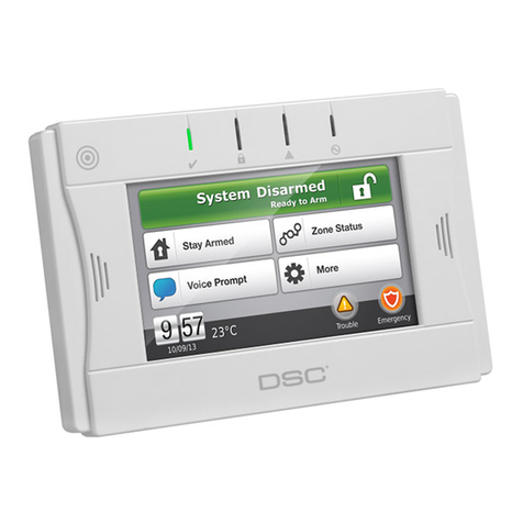
The Model RCP-1 Panel uses LEDs and
keys as its primary means of display-
ing status information and controlling
the system. It allows the occupants to
monitor the status of the Model RCP-1
Panel and its circuits.
The Operator Interface is organized
with the LEDs located along the left and
right sides and keys along the lower
edge, see Figure 5.
LEDs
• ALARM LEDs
A ashing red LED adjacent to the
Sprinkler (IDC1) indicates an alarm.
• TROUBLE LEDs
A ashing yellow TROUBLE LED
for one of the IDCs, NACs, or RACs
indicates the presence of a circuit
break or ground within a system
point, or somewhere in the wiring
between the control panel and one
of its points.
• SUPERVISORY
A ashing yellow SUPERVISORY
LED indicates a problem with the
condition of the sprinkler system
controls or normal status (for exam-
ple, closed valve position for main
control valve, closed valve position
for system control valve, or high air
condition).
• SYSTEM TROUBLE
When a trouble occurs, the SYS-
TEM TROUBLE LED ashes until
accepted. When accepted, it
changes from ashing to steady.
• AC POWER
When lit steady, the green AC
POWER LED indicates the elec-
tronic control is receiving AC power
that is within the specied range.
If the LED is not lit and the panel is
still functioning, electronic control is
using battery power to operate. The
cause for loss of AC Power should
be determined and corrected. The
system is in a normal standby con-
dition when only the Green AC
POWER LED is ON.
CPVC Pipe and Fittings
Corrosion-resistant or internally gal-
vanized pipe must be utilized with the
sprinklers described in this data sheet.
TYCO BLAZEMASTER CPVC Pipe and
Fittings have been specically listed
for use in dry systems. Users must be
familiar with and follow listing parame-
ters, such as, maximum 15 psi (1,0 bar)
air pressure when utilizing CPVC prod-
ucts in a dry-type system.
To facilitate draining, piping in areas
subject to freezing shall be pitched in
accordance with NFPA 13D for dry pipe
systems.
The TYCO CPVC Sprinkler Head
Adapter Tee (P/N 80259) is to be
used with the dry-type residential
pendent sprinklers in dry pipe system
installations.
Refer to the TYCO technical manual
CPVC Fire Sprinkler Products Installa-
tion Instructions & Technical Handbook
(IH-1900).
Water Delivery
For dry pipe systems, the require-
ments for Dry System Water Delivery
per Section 8.3.4.3 of the 2010 edition
of NFPA 13D applies. Water deliv-
ery to the most remote single sprin-
kler for a residential hazard shall not
exceed 15 seconds. The use of the
TYCO SprinkFDT Fluid Delivery cal-
culation program is recommended to
assure a properly operating system can
be achieved prior to constructing the
actual installation.
Figures 1 and 2 provide a sample sprin-
kler layout and water delivery times that
can be expected for a dry pipe sprin-
kler system.
As an alternative to using a Listed
water delivery calculation program and
method as referenced in NFPA 13D, an
inspector’s test connection providing a
ow equivalent to the smallest orice
sprinkler may be utilized, wherein the
test orice is located on the end of
the pipe supplying the most remote
sprinkler.
NOTICE
In no case shall the time of water deliv-
ery exceed 15 seconds for the most
remote operating sprinkler.
Hydraulic Design (NFPA 13D)
The minimum required sprinkler ow
rates for systems designed to NFPA
13D (dry systems) are given in Tables A
to F as a function of temperature rating
and the maximum allowable coverage
areas. The sprinkler ow rate is the
minimum required discharge from each
of the total number of design sprinklers
(the two most hydraulically demanding
sprinklers) as specied in NFPA 13D.
