manuals.online logo
Brands
  1. Home
  2. •
  3. Brands
  4. •
  5. Tyco
  6. •
  7. Irrigation System
  8. •
  9. Tyco ILLUSION User manual

Tyco ILLUSION User manual

General
Description
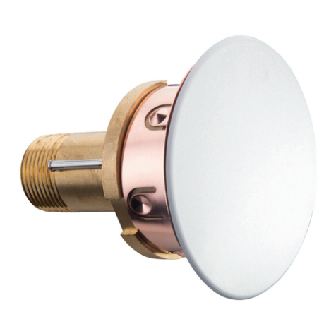
The TYCO ILLUSION, 11.2 K-factor,
Extra Large Orifice Concealed Pen-
dent Sprinklers quick, response, stan-
dard coverage, are decorative, fast
response solder type sprinklers fea-
turing a flat cover plate designed to
conceal the sprinkler. When limited
water pressure is available and a high-
er applied water density is necessary,
the ILLUSION is the best choice for
architecturally sensitive areas such
as casinos, hotel lobbies, office build-
ings, churches, and restaurants.
Each unit includes a Cover Plate As-
sembly that conceals the sprinkler op-
erating components above the ceiling.
The separable two-piece design of the
Cover Plate and Support Cup Assem-
blies allows installation of the sprin-
klers and pressure testing of the fire
protection system prior to installation
of a suspended ceiling or application
of the finish coating to a fixed ceiling.
They also permit removal of suspend-
ed ceiling panels for access to build-
ing service equipment without having
to first shut down the fire protection
system and remove sprinklers.
Also, the separable two-piece design
of the Sprinkler provides for 3/4 inch
(19,1 mm) of vertical adjustment to
provide a measure of flexibility with re-
gard to which the length of fixed pipe
drops to the sprinklers must be cut.
The ILLUSION Sprinklers are shipped
with a Disposable Protective Cap.
The Protective Cap is temporarily re-
moved for installation, and it can be
replaced to help protect the sprinkler
while the ceiling is being installed or
finished. The tip of the Protective Cap
can also be used to mark the center
of the ceiling hole into plaster board,
ceiling tiles, etc. by gently pushing the
ceiling product against the Protec-
tive Cap. When the ceiling installation
is complete, the Protective Cap is re-
moved and the Cover Plate Assembly
installed.
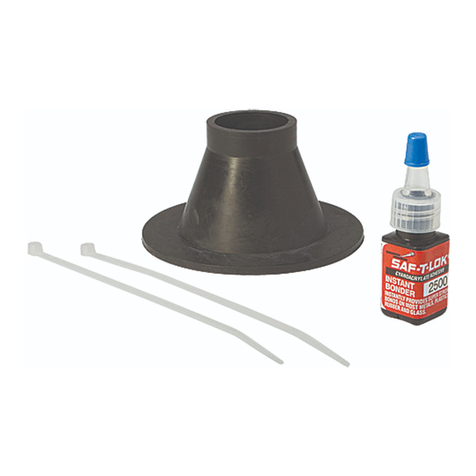
As an option, the ILLUSION Pendent
Sprinklers may be fitted with a silicone
Air and Dust Seal (Ref. Fig. 4). The Air
and Dust Seal is intended for sensitive
areas where it is desirable to stop air
and dust travel through the cover plate
from the area above the ceiling.
NOTICE
The ILLUSION Concealed Pendent
Sprinklers described herein must be
installed and maintained in compli-
ance with this document and with the
applicable standards of the National
Fire Protection Association, in addi-
tion to the standards of any other au-
thorities having jurisdiction. Failure to
do so may impair the performance of
these devices.
The owner is responsible for maintain-
ing their fire protection system and
devices in proper operating condition.
The installing contractor or sprinkler
manufacturer should be contacted
with any questions.
Sprinkler
Identification
Numbers
TY5521
ILLUSION — 11.2 K-factor
Extra Large Orifice Concealed Pendent Sprinklers
Quick Response, Standard Coverage
Page 1 of 4 MARCH 2013 TFP184
IMPORTANT
Always refer to Technical Data
Sheet TFP700 for the “INSTALLER
WARNING” that provides cautions
with respect to handling and instal-
lation of sprinkler systems and com-
ponents. Improper handling and in-
stallation can permanently damage
a sprinkler system or its compo-
nents and cause the sprinkler to fail
to operate in a fire situation or cause
it to operate prematurely.
SPRINKLER/SUPPORT CUP
ASSEMBLY
COVER PLATE/RETAINER
ASSEMBLY
LEVER
DEFLECTOR
SADDLE
BODY
(3/4" NPT)
CAP
COVER
PLATE
EJECTION
SPRING
RETAINER
WITH THREAD
DIMPLES
SOLDER
TAB
SEALING
ASSEMBLY
COMPRESSION
SCREW
DEFLECTOR
(OPERATED
POSITION)
SPRINKLER
WRENCHING
AREA
SOLDER LINK
ELEMENT
SUPPORT
CUP WITH
ROLL FORMED
THREADS
GUIDE
PIN
GUIDE PIN
HOUSING
THREAD INTO
SUPPORT
CUP UNTIL
MOUNTING
SURFACE IS
FLUSH WITH
CEILING
FIGURE 1
THE ILLUSION (TY5521)
CONCEALED PENDENT SPRINKLER ASSEMBLY
Technical
Data
Approvals
UL and C-UL Listed.
(The listings apply only to the service
conditions indicated in the Design Cri-
teria section.)
Approvals for Air & Dust Seal
UL and C-UL Listed for use with the
ILLUSION (TY5521); however, use of
the Air & Dust Seal changes the sprin-
kler response rating from quick to
standard.
Maximum Working Pressure
175 psi (12,1 bar)
Discharge Coefficient
K = 11.2 GPM/psi1/2 (161,3 LPM/
bar1/2)
Temperature Ratings
160°F (71°C) Sprinkler/139°F (59°C)
Plate
212°F (100°C) Sprinkler/165°F (74°C)
Plate
Adjustment
3/4 inch (19,1 mm)
Finishes
Cover Plate: Refer to Ordering Proce-
dure section.
Physical Characteristics
Body. . . . . . . . . . . . . . . . . . . . . . . . . Brass
Cap. . . . . . . . . . . . . . . . . . . . . . . . . Bronze
Saddle . . . . . . . . . . . . . . . . . . . . . . . Brass
Sealing Assembly............ Beryllium
Nickel w/TEFLON
Solder Link Halves ..............Nickel
Lever. . . . . . . . . . . . . . . . . . . . . . . . Bronze
Compression Screw............. Brass
Deflector. . . . . . . . . . . . . . . . Bronze/Brass
Guide Pin Housing ............. Bronze
Guide Pins . . . . . . . . . . . . . Stainless Steel
Support Cup. . . . . . . . . . . . . . Plated Steel
Cover Plate. . . . . . . . . . . . . . . . . . . . Brass
Retainer . . . . . . . . . . . . . . . . . . . . . . Brass
Cover Plate Ejection Spring
. . . . . . . . . . . . . . . . . . . . .Stainless Steel
Operation
When exposed to heat from a fire, the
Cover Plate, soldered to the Retainer
at three points, falls away to expose
the Sprinkler Assembly. At this point
the Deflector supported by the Guide
Pins drops down to its operational
position.
When the rated temperature of the
Solder Link Element is reached, the
Link Element separates, allowing the
sprinkler to activate and flow water.
Design
Criteria
The TYCO ILLUSION, 11.2 K-factor,
Extra Large Orifice Concealed Pen-
dent Sprinklers are UL and C-UL List-
ed as quick response -standard spray
sprinklers for use in accordance with
the current NFPA standard; however,
in accordance with its UL and C-UL
Listing it cannot be used for the pro-
tection of storage.
The ILLUSION Concealed Pendent
Sprinklers are only listed and ap-
proved with the ILLUSION Concealed
Cover Plates having a factory applied
finish.
The ILLUSION must not be used in
applications where the air pressure
above the ceiling is greater than that
below. Down drafts through the Sup-
port Cup could delay sprinkler opera-
tion in a fire situation.
Installation
The TYCO ILLUSION, 11.2 K-factor,
Extra Large Orifice Concealed Pen-
dent Sprinklers must be in-stalled in
accordance with this section.
General Instructions
A 3/4 inch NPT sprinkler joint should
be obtained with a minimum to maxi-
mum torque of 10 to 20 ft.-lbs. (13,4 to
26,8 Nm). Higher levels of torque may
TFP184
Page 2 of 4
3-3/16" DIA.
(81,0 mm)
2-1/2" DIA.
(63,5 mm)
MOUNTING
SURFACE
3/16"
(4,8 mm)
FACE OF
SPRINKLER
FITTING
DEFLECTOR IN
OPERATED POSITION
3/4" (19,1 mm)
THREADED
ADJUSTMENT
SPRINKLER-
SUPPORT CUP
ASSEMBLY
OPERATED
SPRINKLER
SPRINKLER-
SUPPORT CUP
ASSEMBLY
COVER-
RETAINER
ASSEMBLY
COVER
PLATE
RETAINER
DISPOSABLE
PROTECTIVE CAP
3/4"
NPT
TIP
3/8" (9,5 mm)
1-1/8" (28,6 mm)
3/32" GAP
(2,4 mm)
2-1/8"±3/8"
(54,0 mm
±9,5 mm)
FIGURE 2
THE ILLUSION PENDENT SPRINKLER INSTALLATION DIMENSIONS
FRAME
ARM
SUPPORT
CUP
ACCEPTS
1/2" DRIVE OR
7/8" OPEN-END
WRENCH
ALIGN
ARROWS WITH
FRAME ARMS
SPRINKLER
WRENCHING
HEX
WRENCH HEX
RECESS
FIGURE 3
W-TYPE 18 SPRINKLER WRENCH
distort the sprinkler inlet with conse-
quent leakage or impairment of the
sprinkler.
Do not attempt to compensate for in-
sufficient adjustment in the Sprinkler
Assembly by under-or over-tightening
the Sprinkler/Support Cup Assembly.
Readjust the position of the sprinkler
fitting to suit.
Step 1. The sprinkler must only be in-
stalled in the pendent position and
with the centerline of the sprinkler per-
pendicular to the mounting surface.
Step 2. Remove the Protective Cap.
Step 3. With pipe thread sealant ap-
plied to the pipe threads, hand tighten
the sprinkler into the sprinkler fitting.
Step 4. Wrench tighten the sprinkler
using only the W-Type 18 Sprinkler
Wrench (Ref. Figure 3). The W-Type
18 Sprinkler Wrench is to be applied
to the Sprinkler as shown in Figure 3.
Step 5. Replace the Protective Cap
(Ref. Figure 2) by pushing it upwards
until it bottoms out against the Sup-
port Cup. The Protective Cap helps
prevent damage to the Deflector and
Arms during ceiling installation and/or
during application of the finish coating
of the ceiling. It may also be used to
locate the center of the clearance hole
by gently pushing the ceiling material
against the center point of the Protec-
tive Cap.
NOTICE
As long as the Protective Cap remains
in place, the system is considered to
be “Out of Service”.
Step 6. After the ceiling has been
completed with the 2-1/2 inch (63,5
mm) diameter clearance hole and in
preparation for installing the Cover
Plate Assembly, remove and discard
the Protective Cap, and verify that the
Deflector moves up and down freely. If
the Sprinkler has been damaged and
the Deflector does not move up and
down freely, replace the entire Sprin-
kler assembly. Do not attempt to mod-
ify or repair a damaged sprinkler.
Step 7. When installing an Air and
Dust Seal, refer to Figure 4, otherwise
proceed to Step 8. To attach the Air
and Dust Seal, verify the angle of the
outside edge of the seal is oriented
according to Figure 4. Start the edge
of the Retainer in the grooved slot of
the Air and Dust Seal and continue
around the retainer until the entire Air
and Dust Seal is engaged.
Step 8. Screw on the Cover Plate/Re-
tainer Assembly until the Retainer Fig-
ure 2 (or Air and Dust Seal -Figure 4)
makes contact with the ceiling. Do not
continue to screw on the Cover Plate/
Retainer Assembly such that it lifts a
ceiling panel out of its normal position.
If the Cover Plate/Retainer Assembly
TFP184
Page 3 of 4
COVER
PLATE
RETAINER
ASSEMBLY
SPRINKLERSUPPORT
CUP
FACE OF
CEILING
ORIENT
SEAL
BEVEL AS
SHOWN
AIR
AND DUST
SEAL
LIP OF
RETAINER
COVER
PLATE
FIGURE 4
OPTIONAL AIR AND DUST SEAL FOR THE ILLUSION (TY5521)
cannot be engaged with the Support
Cup or the Cover Plate/Retainer As-
sembly cannot be engaged sufficient-
ly to contact the ceiling, the Sprinkler
Fitting must be repositioned.
Care and
Maintenance
The TYCO ILLUSION, 11.2 K-factor,
Extra Large Orifice Concealed Pen-
dent Sprinklers must be maintained
and serviced in accordance with this
section.
Absence of the Cover Plate Assembly
may delay sprinkler operation in a fire
situation.
When properly installed, there is a
nominal 3/32 inch (2,4 mm) air gap
between the lip of the Cover Plate
and the ceiling, as shown in Figure
2. This air gap is necessary for prop-
er operation of the sprinkler by allow-
ing heat flow from a fire to pass below
and above the Cover Plate to help as-
sure appropriate release of the Cover
Plate in a fire situation. If the ceiling is
to be repainted after the installation of
the Sprinkler, care must be exercised
to ensure that the new paint does not
seal off any of the air gap.
Factory painted Cover Plates must
not be repainted. They should be re-
placed, if necessary, by factory paint-
ed units. Non-factory applied paint
may adversely delay or prevent sprin-
kler operation in the event of a fire.
Do not pull the Cover Plate relative to
the Enclosure. Separation may result.
Before closing a fire protection sys-
tem main control valve for mainte-
nance work on the fire protection sys-
tem that it controls, permission to shut
down the affected fire protection sys-
tem must be obtained from the prop-
er authorities and all personnel who
may be affected by this action must
be notified.
Sprinklers that are found to be leaking
or exhibiting visible signs of corrosion
must be replaced.
Automatic sprinklers must never be
painted, plated, coated or otherwise
altered after leaving the factory. Modi-
fied or over heated sprinklers must be
replaced.
Care must be exercised to avoid dam-
age to the sprinklers -before, during,
and after installation. Sprinklers dam-
aged by dropping, striking, wrench
twist/slippage, or the like, must be
replaced. Also, replace any sprinkler
that has a cracked bulb or that has
lost liquid from its bulb. (Ref. Installa-
tion Section).
If a sprinkler must be removed, do not
reinstall it or a replacement without re-
installing the Cover Plate Assembly.
If a Cover Plate Assembly becomes
dislodged during service, replace it
immediately.
The owner is responsible for the in-
spection, testing, and maintenance
of their fire protection system and de-
vices in compliance with this docu-
ment, as well as with the applicable
standards of the National Fire Pro-
tection Association (e.g., NFPA 25), in
addition to the standards of any oth-
er authorities having jurisdiction. The
installing contractor or sprinkler man-
ufacturer should be contacted relative
to any questions.
Automatic sprinkler systems should
be inspected, tested, and maintained
by a qualified Inspection Service in
accordance with local requirements
and/or national codes.
Ordering
Procedure
Contact your local distributor for avail-
ability. When placing an order, indi-
cate the full product name and Part
Number (P/N).
Sprinkler Assembly:
Specify: ILLUSION (TY5521), Ex-
tra Large Orifice Concealed Pen-
dent Sprinkler with (specify) temper-
ature rating and (specify) finish, P/N
(specify).
160°F (71°C) 212°F (100°C)
TY5521 50-711-1-160 50-711-1-212
Separately Ordered Cover Plate:
Specify: ILLUSION Cover Plate, (spec-
ify) temperature rating with (specify)
finish, P/N (specify).
139°F (59°C)(a) 165°F (74°C )(b)
Grey White (RAL9002)
. . . . . . . . . 56-892-0-135 56-892-0-165
Brass ....56-892-1-135 56 -892-1-165
Pure White (c) (RAL9010 )
. . . . . . . . . 56-892-3-135 56-892-3-165
Signal White (RAL9003)
. . . . . . . . . 56-892-4-135 56-892-4-165
Chrome...56-892-8-135 56-892-8-165
Brush Chrome
. . . . . . . . . 56-892-9-135 56-892-9-165
Custom...56-892-X-135 56-892-X-165
(a) For use with 160°F (71°C) sprinklers.
(b) For use with 212°F (100°C) sprinklers.
(c) Eastern Hemisphere sales only.
Sprinkler Wrench:
Specify: W-Type 18 Sprinkler Wrench,
P/N 56-000-1-265.
Air and Dust Seal:
Specify: Air and Dust Seal,
P/N 56-908-1-001.
TFP184
Page 4 of 4

This manual suits for next models

1

Other Tyco Irrigation System manuals

Tyco DS-ECC Series User manual

Tyco

Tyco DS-ECC Series User manual

Tyco TY-FRB Series User manual

Tyco

Tyco TY-FRB Series User manual

Tyco Rapidresponse LFII Series Operating and maintenance instructions

Tyco

Tyco Rapidresponse LFII Series Operating and maintenance instructions

Tyco RFII Series User manual

Tyco

Tyco RFII Series User manual

Tyco Ultra K17 User manual

Tyco

Tyco Ultra K17 User manual

Tyco EC-11 Series User manual

Tyco

Tyco EC-11 Series User manual

Tyco ILLUSION TY5521 User manual

Tyco

Tyco ILLUSION TY5521 User manual

Tyco Power Pro Series User manual

Tyco

Tyco Power Pro Series User manual

Tyco RSV-1 User manual

Tyco

Tyco RSV-1 User manual

Tyco CHEC User manual

Tyco

Tyco CHEC User manual

Tyco Rapidresponse LFII Series Operating and maintenance instructions

Tyco

Tyco Rapidresponse LFII Series Operating and maintenance instructions

Tyco RFII-MRI Series User manual

Tyco

Tyco RFII-MRI Series User manual

Tyco TY-L Series User manual

Tyco

Tyco TY-L Series User manual

Tyco RFII Series User manual

Tyco

Tyco RFII Series User manual

Tyco TY-B Series User manual

Tyco

Tyco TY-B Series User manual

Tyco AQUAMIST ULF AM22 User manual

Tyco

Tyco AQUAMIST ULF AM22 User manual

Tyco TY-FRB Series User manual

Tyco

Tyco TY-FRB Series User manual

Tyco TY-FRB Series User manual

Tyco

Tyco TY-FRB Series User manual

Tyco RAPID RESPONSE Series User manual

Tyco

Tyco RAPID RESPONSE Series User manual

Tyco DS-1 Series User manual

Tyco

Tyco DS-1 Series User manual

Tyco ESFR-17 User manual

Tyco

Tyco ESFR-17 User manual

Tyco ESFR-22 User manual

Tyco

Tyco ESFR-22 User manual

Tyco CC2 User manual

Tyco

Tyco CC2 User manual

Tyco ESFR-1 User manual

Tyco

Tyco ESFR-1 User manual

Popular Irrigation System manuals by other brands

Gardena 1354 Assembly instructions

Gardena

Gardena 1354 Assembly instructions

Autopot 12Pot XL Set-up guidelines

Autopot

Autopot 12Pot XL Set-up guidelines

Viking Microfast M-5 Technical data

Viking

Viking Microfast M-5 Technical data

NeilMed SinuGator Directions for use

NeilMed

NeilMed SinuGator Directions for use

Autopot SmartPot 60 XL Set-up guidelines

Autopot

Autopot SmartPot 60 XL Set-up guidelines

Irritrol 450R Setting instructions

Irritrol

Irritrol 450R Setting instructions

MAZE Moisture Sensing Irrigation Kit instructions

MAZE

MAZE Moisture Sensing Irrigation Kit instructions

Irritrol TITAN user guide

Irritrol

Irritrol TITAN user guide

RainPoint ITV101P user manual

RainPoint

RainPoint ITV101P user manual

ARABLE Mark 3 quick start guide

ARABLE

ARABLE Mark 3 quick start guide

Reliable JL14 Installation

Reliable

Reliable JL14 Installation

Tyco Fire Product Star Galaxy SGQR instruction manual

Tyco Fire Product

Tyco Fire Product Star Galaxy SGQR instruction manual

Reliable DD56-6 Bulletin

Reliable

Reliable DD56-6 Bulletin

Reliable F156 Series Bulletin

Reliable

Reliable F156 Series Bulletin

Tyco Fire Product CENTRAL ESLO-20 GB instruction manual

Tyco Fire Product

Tyco Fire Product CENTRAL ESLO-20 GB instruction manual

Senju Sprinkler FR-QR manual

Senju Sprinkler

Senju Sprinkler FR-QR manual

Tyco Fire Product central bvr instruction manual

Tyco Fire Product

Tyco Fire Product central bvr instruction manual

Viking HORIZON MIRAGE Technical data

Viking

Viking HORIZON MIRAGE Technical data

manuals.online logo
manuals.online logoBrands
  • About & Mission
  • Contact us
  • Privacy Policy
  • Terms and Conditions

Copyright 2025 Manuals.Online. All Rights Reserved.