UNIA HARRIER Operating instructions


OPERATING AND MAINTENANCE MANUAL HARRIER
- 1 -
CE Declaration of Conformity
UNIA Sp. z o.o.
st. Szosa Torunska 32/38
86 – 300 Grudziadz, Poland
Herewith declare with full responsibility that our product:
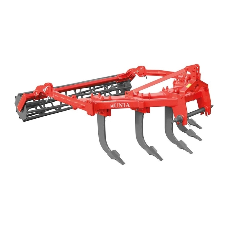
chisel plough
HARRIER
type / model : …………………………………….
manufacturing year : ……………………………..
serial no. : ………………………………………..
is in compliance with the Ordinance of the Minister of
Economy of October 21, 2008 (Journal of Laws No. 199, item
1228) and the EU Directive 2006/42/EC of May 17, 2006 and the
Ordinance of the Minister of Infrastructure of May 4, 2009 (
Journal of Laws No. 75/2009, item 639) and the following
standards:
PN-EN ISO 12100:2012
PN-EN-ISO 13857:2010
PN-ISO 3600:1998
PN-EN-ISO 4413:2011
PN-ISO 11684:1998
PN-EN 349+A1:2010
PN-EN ISO 11688-1:2010
PN-EN 14017+A2:2009
PN-EN ISO 4254-1:2016-02
PN-EN 13739-1:2012
This CE Declaration of Conformity is no longer valid if the
machine has been modified or reconstructed without the
manufacturer’s consent.
Grudziądz, 05.12.2017


OPERATING AND MAINTENANCE MANUAL HARRIER
UNIA Sp. z o.o.
st. Szosa Torunska 32/38
PL 86 – 300 Grudziadz
tel. + 48 56 451 05 00
fax. + 48 56 451 05 01
Service tel. + 48 56 451 05 26
uniamachines.com
chisel plough
HARRIER
MAINTENANCE AND OPERATING
MANUAL
Machine identification data:
Type
Production year
Serial no.
This maintenance and operating manual is an integral part of the
machine. It is important that the manual is always in the possession
of the machine user. Access to the manual should be provided to
machine operators and cooperating persons while operation,
regulation, repairs and renovations.
Before starting the machine please read the
operating manual and follow the recommendations
and instructions regarding safety and proper usage
of the machine.

OPERATING AND MAINTENANCE MANUAL HARRIER
- 4 -
Table of contents
PREFACE: ............................................................................................................................................... 5
1.
Precautions ..................................................................................................................................... 5
1.1 Before you Begin to Use Your Machine...................................................................................... 5
1.2 Health and safety regulation ...................................................................................................... 5
1.3 Servicing...................................................................................................................................... 7
1.4 Transport on highways ............................................................................................................... 7
1.5 Safety Symbols............................................................................................................................ 7
1.6 Nameplate .................................................................................................................................. 9
2.
Technical and Identification Data ................................................................................................. 10
2.1 HARRIER Specification .............................................................................................................. 11
3.
Operating Manual......................................................................................................................... 12
3.1 First Start .................................................................................................................................. 12
3.2 Preparation of the Machine ..................................................................................................... 12
3.3 Mounting and Disconnection of machines............................................................................... 13
a)
mounting .......................................................................................................................... 13
b)
disconnecting.................................................................................................................... 13
3.4 Access to the Field – Transport ................................................................................................ 14
3.5 Adjusting the Machine.............................................................................................................. 15
3.5.1 Levelling of Rollers............................................................................................................ 15
3.5.2 Working Depth Adjustment.............................................................................................. 15
3.5.3 Tine Protection Methods.................................................................................................. 16
a)
bolt protection.................................................................................................................... 16
b)
hydraulic protection ........................................................................................................... 17
3.5.4 Tine Working Components ............................................................................................. 19
4.
Operation...................................................................................................................................... 19
5.
Servicing and Maintenance........................................................................................................... 20
5.1 General ..................................................................................................................................... 20
5.2 Replacement of the Machine Components.............................................................................. 20
5.3 Hydraulic System ...................................................................................................................... 20
5.4 Lighting ..................................................................................................................................... 21
5.5 Bolt, screw and nut tightening torques (Nm)........................................................................... 21
5.6 Lubrication................................................................................................................................ 22
5.7 Storage of the Machine ............................................................................................................ 23
5.8 Disassembly and Disposal......................................................................................................... 23
5.9 Warranty Conditions and Warranty Services ........................................................................... 23
OPERATING AND MAINTENANCE MANUAL HARRIER
- 5 -
PREFACE:
When buying the machine, check completeness of its accessories that include the following
components:
•Operating Manual
•Warranty Card
1.
Precautions
1.1 Before you Begin to Use Your Machine
•Read the instruction manual.
•Pay always special attention to the text and illustrations marked with this
symbol!
•These machines are intended for agricultural use only. Any use outside of this purpose shall
be considered as not intended use. Learn how to use your machine correctly and carefully!
•The machine may be dangerous when operated by not authorized individual or when
operated carelessly.
1.2 Health and safety regulation
•Before each start, check whether the tractor and machine are safe for road traffic and
operation!
•The tractor working with the machine must be equipped with the weights on the front axis
or on front jack. Balance of the tractor with the attached machine, its steerability and
braking ability must always be kept.
•When connecting and disconnecting the machine to/from the tractor, its lifting and
lowering on the hydraulic lift of the tractor, setting the machine in the transport and
working positions and on the headlands, ensure that no bystanders and in particular
children are present in the vicinity of the machine. Perform these operations slowly, without
sudden jerks!
•Never stay between the tractor and the machine when the tractor’s engine is running!
•The machine may only be operated, maintained and repaired by the personnel who know
its construction and are aware of the existing hazards!
•There are some places where crushing or cutting may occur on the parts actuated by the
forces other than the human force (e.g. the hydraulic system). When connecting the
hydraulic hoses to the hydraulic system of the tractor, always ensure that the hydraulics is
depressurized! Check positions of the control levers of the tractor hydraulic system. Only
actuate the hydraulically operated attachments when there is nobody present within their
range of operation! Check the hydraulic hoses on regular basis and replace them with new
items when damaged or worn!
•When driving on highways with the machine attached, lock the operating lever against its
lowering!
•The attached warning and indicating signs contain information on safe work: they are

OPERATING AND MAINTENANCE MANUAL HARRIER
- 6 -
intended for your safety!
•Before you start work, learn thoroughly operation of all devices and actuators and functions
of the machine. It is too late for this after you start work!
•Avoid wearing any loose clothing, which could be caught by rotating components of the
machine.
•Always keep the machine clean in order to avoid the danger of fire!
•Always check the surroundings before you start operation. Make sure that you have
sufficient visibility!!
•Never back or reverse the tractor when the machine is lowered to the working position.
When reversing, pay attention to the components that protrude far away and do not use
the independent brakes of the tractor!
•Check air pressure in the wheels of the tractor and the machine regularly.
•Never transport people on the machine and load it with any additional weights when
operating the machine or transporting it!
•Check and attach the traffic equipment, such as lighting, warning devices and possible
protective devices.
•Observe the admissible axial loads, total weights and transport dimensions.
•Check tightness of screws and nuts on regular basis and tighten them if required.
•Always use appropriate tools and wear safety gloves when changing tools.
•The spare parts must be conforming to the revisions specified by the manufacturer. This
may only be provided by the genuine spare parts. Use typical protection devices and pins
for securing all bolts of the machines (tractor + machine). Never use any temporary means
of protection, such as screws, bars, and wires etc., which can cause damage to the machine
or tractor during transport and cause a safety hazard for other road users!
•Attach and disconnect the machine to/from the tractor after having parked the machine on
a flat and hardened surface and with the tractor engine stopped. Store the machines
unfolded.
•Store the machine in the locations inaccessible for unauthorized people or animals when
not in use.
•Besides the above guidelines, follow the general safety rules.

OPERATING AND MAINTENANCE MANUAL HARRIER
- 7 -
1.3 Servicing
•Service the machine when it is lowered onto the ground! If the machine is
coupled with the tractor, engine of the tractor must be off and brakes on!
•Use only tools in good technical condition and genuine materials and spare
parts for servicing.
•Always protect the machine with appropriate supports when performing any maintenance
or repair work on the machine lifted up.
1.4 Transport on highways
•Never exceed the speed limits allowed on highways and follow traffic
regulations of the respective country!
•Pay special attention when passing and overtaking other vehicles and on
curves (the unit is pivotally connected to the tractor)!
•The machine, as the part of the vehicle that protrudes outside the rear side outline of the
tractor covering the rear lamps of the tractor, poses a threat for other vehicles in the traffic.
•When transporting the machine on highways, always use warning lights, distinguishing plate
and side reflectors.
•Maximum width of the machine, which can be moved on highways is specified in the
detailed regulations of the country of use. They should be observed.
1.5 Safety Symbols
A
Read through the Operating Manual thoroughly before operating the
machine
B
Stop the tractor engine and take away the ignition key before any
servicing and repair work
C Keep safe distance off the machine
D
Never reach into the crushing area as long as the components can
move
E Stay away of the machine tilting area

OPERATING AND MAINTENANCE MANUAL HARRIER
- 8 -
I
ACCORDING TO THE ROAD SAFETY REGULATIONS (REGULATION OF THE MINISTER OF
INFRASTRUCTURE OF 31/12/2002 - DZ. U. NO. 32 OF 2002, ITEM 262), DRIVE ON HIGHWAYS ONLY
AFTER HAVING OBTAINED AUTHORIZATION FROM THE COMPETENT HIGHWAYS
ADMINISTRATION BODY WHERE THE JOURNEY BEGINS.
For the machines that exceed the allowable transport width 3.0m
Safety signs and inscriptions should be protected against damage, dirt and overpainting.
Replace any damaged or illegible signs and inscriptions with new ones that are available
from the manufacturer or vendor of the machines.
F
Points of attaching hooks of the lifting equipment
G
UWAGA
PROSIMY O REGULARNE SMAROWANIE
PUNKTÓW SMARNYCH
ATTENTION
PLEASE OIL REGULARLY LUBRICATION
POINTS UNDER THE OPERATING
MANUAL
ACHTUNG
WIR BITTEN REGELMABIG DIE
SCHMEIRSTELLEN LAUT
BEDIENUNGSANLEITUNG ZU
SCHMIEREN
Lubricate the machine on regular basis

OPERATING AND MAINTENANCE MANUAL HARRIER
- 9 -
Fig 1: Location of the safety symbols
1.6 Nameplate
For the machine data, see the type plate that is attached in the front section of the machine.

OPERATING AND MAINTENANCE MANUAL HARRIER
- 10 -
2.
Technical and Identification Data
HARRIER – is a chisel plough used for ploughless cultivation, which works well in simplified
cultivation technology.
HARRIER B – bolt-protected tine
HARRIER H – NON-STOP
hydraulic protection
These machines are delivered with the following accessories as a standard:
•ø36 Cat. III coupling / ø51N, Cat. IV coupling
•3m wide frame – 5 tines, spaced of 605mm
•3m wide frame – 7 tines, spaced of 440mm
•4m wide frame – 7 tines, spaced of 605mm
•4m wide frame – 9 tines, spaced of 440mm
•width between rows of tines: 100cm
•working depth down to 50cm
•double spiky roller
•ø20 bolt protection (HARRIER B)
•NON-STOP hydraulic protection (HARRIER H)
Optional accessories:
•a set of warning signs
•a set of warning signs with lights
•extension of the barbed roller
The machines are manufactured in the following widths:
3.0m; 4.0m
Roller overhang Set of warning signs (lighting)
Leg
Frame
Bolt-protected (hydraulically-protected) tine
Cylinder
Roller extensions (option)
Spiky roller
Fig. 2. Construction of HARRIER

OPERATING AND MAINTENANCE MANUAL HARRIER
- 11 -
2.1 HARRIER Specification
Table 1.
Item Parameter
U/m
Type of machine
1 Type of machine unit
-
B5 3.0 B7 3.0 H5 3.0 H7 3.0 B7 4.0 B9 4.0 H7 4.0 H9 4.0
2 Working width m 3 4
3 No. of tines pc. 5 7 5 7 7 9 7 9
4 Max working depth cm 50
5 Type of protection
bolt hydraulic bolt hydraulic
6 Tine pitch cm 60.5 44 60.5 44 60.5 44 60.5 44
7 Working speed km/h 6-10
8 Capacity ha/h 1.8÷3.3 2.4÷4
9 Power demand HP 180-240 240-280 180-240 240-280 280-320 320-380 280-320 320-380
10 Operators No. 1
11
Dimensions
without
optional
accessories
L
cm
380
W 300 400
H 162 182 162 182
12 Transport width m 3 4
13 Coupling category
3 and 4N
14 Weight with roller kg 2480 2690 2990 3390 2900 3110 3590 3990

OPERATING AND MAINTENANCE MANUAL HARRIER
- 12 -
3.
Operating Manual
3.1 First Start
Before the first start of the machine:
•read the Operating Manual thoroughly
•check technical condition of the machine, and in particular, condition of its working parts,
tines protection against overload and the hydraulic system. When finding any damaged or
worn parts, replace them with new ones
•check tightening of all screws, bolts and nuts. Tighten any loose nuts especially at the
beginning of operation of the machine
•check fitting of the quick-connectors of the hydraulic hoses of the machine to the sockets
on the tractor
•check, whether the rollers can rotate without any jams
•check the pressure in tyres acc. to the manufacturer’s recommendations
•check, whether the components requiring lubrication are lubricated
•check, whether the machine attachment system fits the tractor attachment system
3.2 Preparation of the Machine
•pressure in the tractor wheels must be equal on the
same axle in order to provide uniform working depth of
the machine
•the tractor lower links (c) must be stiffened (lock the
oblong holes) and at the same height above the ground
level
•set the lifting rods of the tractor links (w) so that you can
pull down the lower links below the hitch axle in order
to achieve the required working depth, while obtaining
sufficient lifting height of the links for transport
•mount the front axle weights in order to keep balance of
the tractor and the machine
•quick-connectors of the machine hydraulic hoses must
fit the sockets on the tractor
•the hitch axle should be in the middle of the machine
•category of the lower articulated joint of the hitch axle
must be the same on both the tractor and the machine
sides!
Fig. 3: Tractor lifting rod
Fig. 4: Front axle weight

OPERATING AND MAINTENANCE MANUAL HARRIER
- 13 -
3.3 Mounting and Disconnection of machines
The tractor should stand on a firm and level ground in order to connect the machine to it in a safe
and correct manner.
Fig. 5. Connecting the machine
a)
mounting
•shift the tractor hydraulics to the position control
•remove the bolt from the hole [D]
•back the tractor to a distance that allows connection of the tractor lower links [C] with the
holes [D]
•insert the bolt, connecting the hole [D] with the lower link [C] in this way. Protect the bolt
with cotter pin
•connect the upper tractor connector [A]. Select position of the upper bolt [B] in the carriage
acc. to the terrain. During work of the cultivator, the upper fixing point should be located
higher than the point of fixing this connector to the tractor
•connect the machine hydraulic hoses to the tractor external hydraulic system and check the
hoses for tightness. Check lifting, lowering and operation of the complete unit hydraulic
system. Remember to connect all hoses to all tractor 2-way hydraulic connectors in pairs
•lift the legs to the transport position and secure
b)
disconnecting
•lower the machine onto a flat and hard surface
•lower the legs to the resting position.
•depressurize the machine hydraulic system by shifting the tractor hydraulic levers to their
free (floating) position
•disconnect the hydraulic hoses from the tractor external hydraulic system
•remove the bolts of the lower links and detach the tractor upper connector

OPERATING AND MAINTENANCE MANUAL HARRIER
- 14 -
3.4 Access to the Field – Transport
Fig. 6. Transport
•width of the machine can be greater than 3.0m, depending on the accessories installed
•lift the legs [A] for transport
•fold the roller extensions [B]. Remove the cotter pins [E] and bolts [D];turn the extension of
180 degrees on the hinge and secure it in the transport position with the pin [F]. Insert the
bolts into the matching holes in the roller and protect them with the cotter pins [E]
•clean the machine from soil and other contaminants after finishing work
•clean the warning components (lighting) (option) [C].
•the unit consisting of a tractor and agricultural machine connected to it must meet the same
requirements as the tractor alone
•adjust the chains tensioning the tractor side links (stabilizer arms) accordingly before driving;
they should limit the excessive side movements of the machine
•Always comply with the ‘Traffic Act’ when driving on highways

OPERATING AND MAINTENANCE MANUAL HARRIER
- 15 -
3.5 Adjusting the Machine
3.5.1 Levelling of Rollers
Level the packing rollers before adjusting the working depth on the roller.
•adjust position of the roller by turning the turnbuckles [A] on both sides of the roller
accordingly. The rollers should be set parallel to the ground surface.
3.5.2 Working Depth Adjustment
HARRIER is designed to operate to a depth of 50cm. Never exceed this value.
Fig. 7. Levelling of Rollers
Fig. 8. Working depth – HARRIER

OPERATING AND MAINTENANCE MANUAL HARRIER
- 16 -
•pressurize the cylinder [A] from the tractor cab, extending it. Then, put the required
number of the stops [B] and pressurize the cylinder [A] again, retracting it to the stops [B].
In this way, you can lift or lower the rear roller of the machine
•while setting the working depth on the cylinder, consider the parallel position of the working
machine. Lower the machine on the tractor linkage accordingly
•repeat the steps several times to achieve the required depth
•after setting the depth, ensure that the packer rollers are set correctly (see par. 3.5.1.)
3.5.3 Tine Protection Methods
a)
bolt protection
Fig 9. Bolt-protected tine
•HARRIER B tines are protected with safety bolts [A] (shear bolt), protecting them against
overload; the bolt will be broken after exceeding the limit value, i.e. 2000kg
•After the safety bolt is cut, lift the machine above the ground; the tine should fall down to
the work position spontaneously. Otherwise, loose the bolt [B] with extreme caution
•never stay in the crush area or insert any part of your body or object when the tine falls
down
•remove the broken protection bolts and insert new ones
•tighten the safety bolt [A] and the bolt [B] to the required torque (see table 2 later in this
manual)
USE ONLY GENUINE PROTECTION DEVICES!!!

OPERATING AND MAINTENANCE MANUAL HARRIER
- 17 -
b)
hydraulic protection
WARNING! THE HYDRAULIC SYSTEM IS UNDER
PRESSURE!
Never manipulate the gas supply valve!
Inspection and maintenance of the pressure accumulator may only be carried out by a
qualified service. Any interference with the pressure accumulator results in a loss of
warranty.
Never disconnect any hydraulic connections when the system is pressurized!
The diaphragm accumulator is filled with nitrogen. The maximum filling pressure is
indicated on the label attached to the accumulator housing
Fig 10. Hydraulic protection – HARRIER H
In order to pressurize the hydraulic system to the required working pressure and to bleed
it:
•clean the hydraulic connections
•connect the hose [A] to the tractor
•open the valves [B] and [E]
•pressurize the machine hydraulic system to the desired working pressure, controlling the
flow with the controller [C], while observing the pressure gauge [D],
•in order to bleed the hydraulic system, lower the machine to the ground, move forward,

OPERATING AND MAINTENANCE MANUAL HARRIER
- 18 -
and slightly lower the tines into the ground, so that all the cylinders retract to their end
positions. With the valve block open, fill and empty the system several times with oil (to
lower the teeth completely). If necessary, repeat the operation several times. Remember
to close the valves [B] and [E] after the last filling
•disconnect the hose [B] from the tractor
Depending on the soil conditions, the recommended working pressure range is 90-120 bar.
The non-stop protection allows the following;
•automatic lifting of tines (i.e. stop operation) after hitting an obstacle
•automatic return of tines to their operating position after passing the obstacle
Fig. 11. Hydraulic protection of the tine
•HARRIER H tines are protected by a NON-STOP hydraulic protection against overload [A]
•Moreover, HARRIER H tines are bolt-protected [B]
USE ONLY GENUINE PROTECTION DEVICES!!!
Pressures on the chisel :
100 bar – 1800 kg
Table of contents
Other UNIA Farm Equipment manuals

UNIA
UNIA MXL Series User manual

UNIA
UNIA Ares HP Operating instructions

UNIA
UNIA HERMES 3.0 User manual

UNIA
UNIA FENIX G User manual

UNIA
UNIA ARES P Operating instructions

UNIA
UNIA CROSS HP Operating instructions

UNIA
UNIA KRET L User manual

UNIA
UNIA MX User manual

UNIA
UNIA AMBER 900/3 User manual

UNIA
UNIA TERIS XL H Series Operating instructions
Popular Farm Equipment manuals by other brands

Land Pride
Land Pride LR3784 Operator's manual

Land Pride
Land Pride SGC0660 Operator's manual

Rinieri
Rinieri CRV Instructions for use and maintanence

SCHMOTZER
SCHMOTZER Venterra 2K KPP-LSC Translation of the original operating instructions

MacDon
MacDon FD75 manual

MacDon
MacDon M105 Unloading and assembly instructions