3
CHAPTER 1 GENERAL ASPECTS........................................................................ 5
1.1
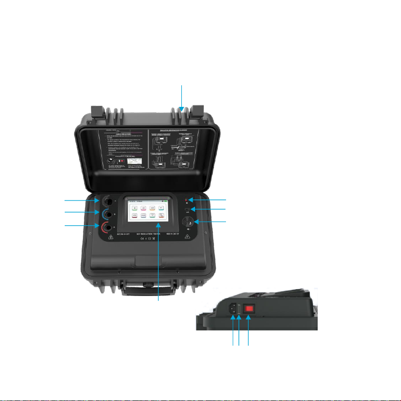
Features of the meter
................................................................................... 5
CHAPTER 2...................................................................................................... 7
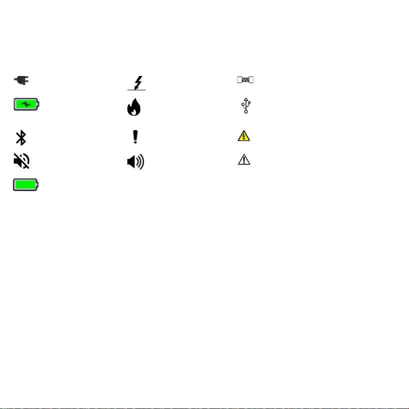
SYMBOLS ON THE INSTRUMENT:....................................................................... 8
CHAPTER 3...................................................................................................... 9
3.2
BASIC INDICATIONS AND THEIR MEANING .......................................... 10
CHAPTER 4.................................................................................................... 11
CHAPTER 5 MEASUREMENT MODES OF THE METER........................................ 13
5.1
IR Mode: ................................................................................................. 13
5.2
DAR Mode: .............................................................................................. 15
5.3
PI Mode:.................................................................................................. 18
5.4
Step Mode: .............................................................................................. 21
5.5
Ramp
Mode:............................................................................................. 25
5.6
Dielectric
Discharge
Mode:
......................................................................... 28
5.7
Voltage Mode: .......................................................................................... 32
CHAPTER 6 GRAPH WINDOW ........................................................................ 33
CHAPTER 7 FILE EXPLORER........................................................................... 36
CHAPTER 8.................................................................................................... 38
CHAPTER 9 SETTINGS OF THE METER............................................................ 39
9.1
SLEEP Mode Settings: ............................................................................... 39
9.2
Time/Date Settings: .................................................................................. 40
9.3
Customer Information Settings: ................................................................. 41